


EDIT: Picasa Web Album with all the Pictures!
Hello Everyone,
I have had this project in the back of my mind for a few years now. Ive been collecting parts and planing my moves. I think it is finally time to get this project rolling so here I am to document it and hopefully get some advice along the way.
My plan is to build a machine that has a +36" X, +24" Y and ~36" Z. This will be a big machine! I want to be able to do high speed machining on aluminum and reasonable machining on steels and iron.
Now, For the pieces I have acquired.
A few years ago, I met a guy that lives about an hour and a half from me that owns a PCB assembly shop. He was scrapping some machines and that's where I started to get my parts. To make a long store short, I was able to get a full XY gantry out of one machine! It uses 48" THK slides for both axis's and precision ground ball screws! The X slides are LWHS 20 series and the Y is LWHS 15's. This was the heart of the component placement machine and was accurate to +/-0.0002" with repeatablity of +/-0.0001". It is super accurate!! It already had servos with all drives and was ready to go!! So I thought.... more on that later...
Anyways, at least the gantry is solid! Now the base and column was the concern. On the back of this same machine was a fabricated I beam that is the back bone of the machine. It was yelling at me that it was perfect for a column for the Z. Cut it in half, and put the 2 half's together and have a hollow column where the Z screw could fit down inside, protected from everything. As an additional bonus, the rail has some of the biggest THK slides I've ever seen on it! LWHD 35's! each slide block is almost as big as my hand and weighs about 5lbs each! When I looked at the spec sheet for these, they have a dynamic rating of 10Klbs each! Well that will take care of the Z.
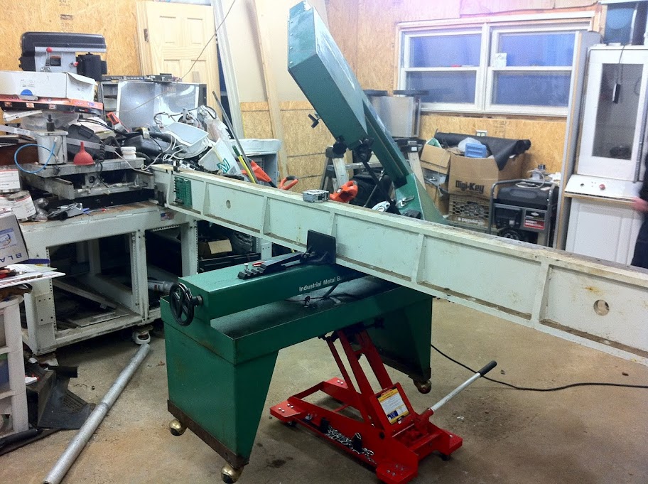
The base was the last part in question. I had my eye on another machine he was scrapping and was able to get my hands on the lower half. The base of this machine was built to be strong. All box steel constructional with 6mm wall thickness, with pieces of box for angled cross bracing galore! The icing on the cake is the top of the frame. 1.125" of solid steel with a machine flat finish! The whole thing is about 5' square and 24" tall. The entire unit would sit on 8 leveling fit, which I replaced with 8 leveling casters so I could roll it around.
A few months went by while I was looking for more parts and designing the machine. I was able to pick up a freshly rebuild spindle on Ebay for a Miyano MSV-21. It will take a BT-30 tool holder and came with 2 draw bars and pull stud grippers. One looks a little worn, but the second looks great! I checked it out when I got it, took measurements and created a 3D model then oiled it down and triple wrapped it up in trash bags to keep it safe.
So that brings me to the controls. For 2 years now I have been trying to figure out what to do with the controls. Everything in the machine was working great. It is all Yaskawa CACR-PR 3 phase AC servo packs. The issue, is this stuff is OLD. It can ONLY be powered by 3 phase power, and only clean power. They are not switching supply side like vfd's and newer servo stuff, but instead SCR based rectifier with phase angle monitoring to control bus voltage. This means that without 3 phase power, they do nothing.
I have been looking around for the 2 years for a suitable replacement control system that I can easily power from single phase.
Well, the other day I came across industrial size stepper motors at an affordable price! There is 3 different models, all 4 wire 1.8* per step motors. They are 107, 185 and 247 oz-LB. yes inch pound. The big one is almost 4000 oz-in! At $90, $100, and $120 respectively, they are very affordable. The smallest one is 100V while the other 2 are 130V My plan now is to sell off the rest of my AC servos and controllers to get some cash for the new controls.
What I am planing to use is the Keling KL-11080 which is a 8A adjustable multi-step drive that accepts 110-220 VAC. No power supply required!
I plan to use one of each size stepper on the machine. The small one for the Y, the medium one for the X and the big one for the Z. I will run the drivers with a PMDX-126 Breakout with Smooth Stepper for pulse generation.
The only things left in question would be the spindle motor and control, but I will figure that out later as I go on. If need be, I have a 3.25HP Porter cable router that the base was damaged on, but the rest is fully functional and almost brand new.
Well I think that is enough talking for now. Here are some pictures!
-Adam
Machine Base:
Gantry On Base:
Spindle with Drawbars:
Cutting the Fabricated I-Beam:
Thread: Very Large VMC Build
Results 1 to 20 of 20
-
07-24-2012, 07:05 PM #1
 Registered

- Join Date
- Jan 2007
- Posts
- 219
Very Large VMC Build
www.adambrunette.com - Converting My Harbor Freight X2 And My Jet Jvm-830 Knee Mill, As well as many other projects.
-
07-24-2012, 08:23 PM #2
Registered
- Join Date
- Sep 2011
- Posts
- 84

First of all, very very nice. You seem to have acquired some nice high quality components. The 36" of Z seems very ambitious, why do you need so much Z height? foam? Rigidity will likely need the most attention, especially if you want to machine metals. I took apart a similar sized milling machine and the whole column was cast iron about 1" thick and had cast supporting ribs on the inside throughout the column. The servos used were also much bigger (180v dc servos, 3 hp) and to support the Z axis it had a pneumatic brake meshed with the gearing of the Z axis.
Keep up the good work.Making chips, day by day
-
07-24-2012, 09:44 PM #3
Gold Member
- Join Date
- Jan 2006
- Posts
- 2985
That X-Y system looks mighty flimsy for machining steel.
High Speed Machining and old surplus steppers driven by cheap electronics?
I think you are dreaming on virtually all counts. Please take a look at the specs for a real VMC and see how your components stack up.
My $0.02
Matt
-
07-24-2012, 10:12 PM #4
Registered
- Join Date
- Jan 2007
- Posts
- 219
Thanks KriegKuts! The parts were just a right place right time kind of thing. As for A height, 36" was just a goal. I always have things I am working on that would be easier if I could just fit it on the milling machine. The Z will be the first piece to be shortened. Originally Posted by KriegKuts

I was planning on counter balancing the head with cat iron weights. The column itself weighs in at just under 600 lbs. The base its about 2300 lbs and the gantry another 400.
-Adam
Sent from my Galaxy Note.www.adambrunette.com - Converting My Harbor Freight X2 And My Jet Jvm-830 Knee Mill, As well as many other projects.
-
07-24-2012, 10:24 PM #5
Registered
- Join Date
- Jan 2007
- Posts
- 219
Hello Matt, Originally Posted by keebler303
I am slightly worried about the Y axis of the gantry. I halve already found some rail upgrades for both axis's. My plan is to only rarely use the machine for milling steel. It will almost do aluminum plastics and wood.
The steppers are actually brand new. The drives are the part I'm really concerned about. At first I was thinking gecko drives, but even at their max of 80 volts, I don't think they are enough. That's why I went looking at the keling drivers and when I found the Mains powered ones, I got a but happier. I would love to just keep the Yaskawa servos and drivers, but it its impassable to run them in my home garage.
My other thought was to use some of the mach motion drives, but the are a bit more then I want to spend. Especially with the weak Y gantry.
Do you have any suggestions on an avoidable motor system? This is just for my hobby and will never make me any money.
Thanks for getting me thinking!
-Adam
Sent from my Galaxy Note.www.adambrunette.com - Converting My Harbor Freight X2 And My Jet Jvm-830 Knee Mill, As well as many other projects.
-
07-25-2012, 01:32 AM #6
Gold Member
- Join Date
- Jan 2006
- Posts
- 2985
Have you looked into a good quality rotary phase converter? The "CNC" rated ones are supposed to have very good characteristics. I looked into one for an old NC lathe I am working on but decided to just upgrade to AC inverter drives for spindle and axes.
This is the brand I use, have one that has been running for over 20 years with no problems: ARCO Electric Products - CNC Roto-Phase
Matt
-
07-25-2012, 05:49 PM #7
Registered
- Join Date
- Apr 2004
- Posts
- 49
Hi Adam. Whoa! This thing is a beast. I like the idea of staying with the 3-phase as long as you can figure out how to either use existing control electronics (if available) or interface your own new stuff. A rotary phase converter is an easy solution, and probably much cheaper in time and money than fitting new servos or steppers. I noticed the following on ebay for $370:
5HP 3 Phase Converter Rotary, 1 To 3 Phase CNC mill | eBay
Neat project.
Ray
-
07-25-2012, 05:51 PM #8
Registered
- Join Date
- Jan 2007
- Posts
- 219
I'm told by the guy running these machines that the drives and servos came from of, they don't like rotary converters or dirty power at all. Originally Posted by keebler303
Another thing I was thinking about this AM was trying to find just a new servo pack that can control a 3 phase motor that has a normal quadrature encoder on it. I'm having some trouble finding one though that things on singles phase.
-Adam
Sent from my Galaxy Note.www.adambrunette.com - Converting My Harbor Freight X2 And My Jet Jvm-830 Knee Mill, As well as many other projects.
-
07-25-2012, 07:59 PM #9
Registered
- Join Date
- Jan 2007
- Posts
- 219
Hey Ray, Originally Posted by bru102
I checked out that rotart converter and gave them a call. They say it produces 120 degree phases and withing 5% voltage regulation. Im thinking I will try it and see how it works. It will save me a TON of money if I can use the stuff I already know I know works.
A couple years ago, I brought 2 servo packs and motors to work with my laptop and smooth stepper to see it all work with mach 3. It worked great!
-Adamwww.adambrunette.com - Converting My Harbor Freight X2 And My Jet Jvm-830 Knee Mill, As well as many other projects.
-
07-25-2012, 09:53 PM #10
Gold Member
- Join Date
- Jan 2006
- Posts
- 2985
A CNC rotary converter gives you clean power, the one I linked to is +/- 2% voltage regulation. They are specifically designed to be used with equipment like you have. Originally Posted by Adamj12b

Matt
-
07-26-2012, 07:53 PM #11
Registered
- Join Date
- Apr 2004
- Posts
- 49
Matt makes a good point about being careful your rotary converter is "cnc rated". Not exactly sure what that means, but the Temco data sheet claims to be designed ground-up for cnc machines
 . Not sure if the 2% vs 5% regulation is a big deal or not...could be worth a little research. I don't believe any equipment is designed to require better than plus or minus 5% because the power company doesn't guarantee it and you have voltage losses in the runs within your home or business.
I only stumbled over the Temco unit due to price, but if the money-back guarantee is for real, it could be worth a try. I assume these are made offshore, but the website and documentation looks like these folks are a serious business. On the other hand, Matt's unit could be the sure bet if the price is OK.
Ray
-
07-26-2012, 09:45 PM #12
Registered
- Join Date
- Apr 2004
- Posts
- 49
Back again... so I found a manual for your servos, and attached a page of interest. It says the 3 phase supply is 200-230 VAC plus 10% minus 15%... so +/- 5% should be no big deal. But I'm interested in the info you had about the need for super clean power... I don't see that any where in the specs. Also, I would think a rotary converter ( a motor-generator) would be cleaner than a utility line by a long shot. Am I missing something??
Be careful about how much power you need... your servopack seems to need 2.1 or 3.0 amps max continuous (not peak)... for just one "03" servopack and motor. Are they all that size? The converter I linked you to was only 7A/2.1kw continuous. You probably need a larger one, especially if you intend to venture into the peak torque area (which means overheating motors if done for any length of time.)
Ray
-
07-27-2012, 02:28 PM #13
Gold Member
- Join Date
- Jan 2006
- Posts
- 2985
Voltage regulation is only one part of the story. For a 3 phase SCR drive, the phase is also quite important. Also note that a standard converter has a "high leg" which is 240V to neutral while the other 2 are 120V to neutral. I am not sure if a CNC converter is the same. Some drive configurations (DC servos/spindles) use the AC neutral as one motor lead and the SCR's control the voltage on the other. In these cases, the voltage to neutral must be equal for all three phases. You can use a delta-wye transformer if necessary to achieve this.
An apps guy at any of the converter companies should be able to get you going as long as you know what you need. The drive manuals should be helpful for that.
Matt
-
07-27-2012, 06:07 PM #14
Registered
- Join Date
- Jan 2007
- Posts
- 219
Ray,
I do already have the manual. The motors that I have are the USESEM-03 for the Y, and USASEM-08 for the X and Z. I have a VFD that will run the spindle whatever it ends up being from single phase so the rotary converter will only be for the servos. The 03 is a 308W servo and the 08's are 771W each. Total would be 1850W.
Im still trying to figure out what they mean by the current ratings on the servo packs. The 3A is the output side of the servo pack. The input side will usually be less unless the servo is running at full speed.
By wattage, the $370 converter is big enough, but if you go by current of motors listed here: http://www.yaskawa.com/site/dmservo.nsf/(DocID)/TKUR-5EJM57/$File/TSE-S800-2.4E.pdf on page 5, its not even close. However, if the voltage is lowered, the current will increase on the motor side. Im going to have to do some more research.
Matt is correct. The phase of the 3 phases is important in this type of drive. Thats what what worried me about a rotary converter. They tell me that the 3 phases are all 120 degrees to each other which makes it sound promising.
These drives do not use the neutral. Just 3 phase for powering the motor section, and then single phase 220 for the logic section of the drive. I will get this power from the wall and not the converter so there is no extra load on the converter.
Im thinking about contacting Temco again and finding out what the overload rating of the XR3 converter is. I think it still might be big enough.
Another option they have is a package where you supply your own idler motor. I do happen to have an extra 10HP baldor fan motor that I got for building a rotary converter.
-Adamwww.adambrunette.com - Converting My Harbor Freight X2 And My Jet Jvm-830 Knee Mill, As well as many other projects.
-
07-27-2012, 07:26 PM #15
Gold Member
- Join Date
- Jan 2006
- Posts
- 2985
Adam
I doubt the "you supply your own idler" setup would be CNC rated. Most of the higher end converters use a specially wound converter, not just a 3 phase motor with the shaft cut off. I could be wrong though.
Matt
-
07-29-2012, 12:43 AM #16
Registered
- Join Date
- Apr 2004
- Posts
- 49
Adam (and Matt)... great thread for exploring 3-phase issues. Yes, I misread output current as input in your manual. Looking more carefully it suggests 0.65 kVA (roughly KW) for the PR03 servopack and 2.1 kVA for the PR10 servopack. Im guessing the PR10's are what you have to run the USASEM-08 motors. Is that right? That would put your 3-phase power needs up around 5KW for the 3 servopacks, well beyond the capability of the 5hp unit we were discussing. I notice the Temco line includes an xr7/10hp supporting cnc loads of 4KW for $734, and an xr11/15hp for cnc loads to 6.1KW for $995. So the price gets higher, and the 2-phase 220v wiring gets larger.
Keeping the spindle out of the 3-phase picture seems like a great call.
Matt has more knowledge here, but the cnc rated phase converters seem to strive for 5% phase to phase voltage regulation, and that is tougher because they must do it for loads from zero (no axis moving) to 6.1KW (max continuous torque on all axes at once) assuming the xr11. Note that Temco and others derate their "cnc" output power to about 60% of max because of the need to provide +/- 5% regulation from 0 to max load. I don't see where the phase angle is an issue... that (I think!!??) is mechanical and should be 120 degrees always.
Ray
-
07-29-2012, 01:01 AM #17
Registered
- Join Date
- Apr 2004
- Posts
- 49
An observation: it starts to look a little cumbersome to invent your own 3-phase power company
 . It looks like it takes a 10-15hp motor generator to supply a maximum of maybe 2.5hp shaft output, total, from 3 servos! Is my math goofed up? Ray
-
07-29-2012, 11:05 PM #18
Registered
- Join Date
- Aug 2008
- Posts
- 1166
If you want to look into this route more, you might look at Mesa drives in conjunction with Linux CNC and the BLDC library. You might also look at Granite Device drives. Originally Posted by Adamj12b
CNC mill build thread: http://www.cnczone.com/forums/vertical_mill_lathe_project_log/110305-gantry_mill.html
-
07-30-2012, 04:40 AM #19
Gold Member
- Join Date
- Jan 2006
- Posts
- 2985
The trouble with servos is you might experience peak torque (current) at zero speed. That means 0.00 mechanical horsepower, even though you may be putting 10A into the motor. It is really more logical to look at the idler motor in terms of amperage rather than power. A 3 phase motor with 10 ft-lb torque at 1800 rpm is a lot of power, whereas 10 ft-lb of torque on a servo at zero speed gives you no mechanical power. Originally Posted by bru102
Matt
-
07-31-2012, 06:19 AM #20
Registered
- Join Date
- Apr 2004
- Posts
- 49
Matt makes a good point about motors needing full amps at zero RPM. That's how they accellerate an axis and apply cutting force. It is unlikely that any servo will run at full hp, since that would occur at 3000 RPM, and that speed probably only happens in a rapid move which is unlikely to require full torque. So maybe Adam's larger motor (1.1hp) will never develop more than, say .75hp.
However, he will need full amps to develop full torque to accellerate 3 axes and cut metal... so you still need a big rotary converter. I think sizing discussions with application engineers at a couple different rotary manufacturers would be worth the effort.
BTW... I messed up earlier when I was thinking these Rotary converters were true motor-generators, the ones we are discussing are not.")
Ray


 Reply With Quote
Similar Threads
-
Build your own large format printer?
By rackbox in forum Printing, Scanners, Vinyl cutting and PlottersReplies: 15Last Post: 09-22-2016, 06:25 PM -
Large EG 5 axis cnc : design & build log
By yellow_submarin in forum Vertical Mill, Lathe Project LogReplies: 25Last Post: 12-15-2012, 10:54 PM -
Heavy large scale gantry mill/router/3d carving 5 axis build
By Tristar500 in forum DIY CNC Router Table MachinesReplies: 20Last Post: 03-18-2010, 12:07 PM -
Large (4'X10') build based on Chinese CO2 tube
By R and G Leather in forum Laser Engraving / Cutting Machine General TopicsReplies: 23Last Post: 04-07-2009, 01:15 AM -
New Large Table Build in Houston, TX (Build Log)
By anitel in forum Plasma, EDM / Other similar machine Project LogReplies: 12Last Post: 12-30-2008, 09:45 AM
