


Thanks, Art. Still got a ways to go... My Gecko G540 came in today. Kind of a puny little thing for that kind of money! But as long as it works...
I'm pairing 20 tooth with 48 tooth pulleys on the X-Y Axes. I need a smaller pair for the Z axis and happened to have a 15 tooth pulley for the motor so to keep the ratio the same as the other axes, I needed a 36 tooth pulley. I know it's not necessary to have the same gear ratio on all axes, but I like consistency. I didn't have a 36 tooth pulley on hand and I didn't want to pay the outrageous price for one, so I decided to make one. Here's a picture of the blanks I turned.
Attachment 208864
I already had a cutter I had made a number of years ago from a 1/8" slitting saw. I had beveled the edges to the proper angle and used it once before to make another pulley. Here it is chucked up in the mill, teeth already cut. I'm using my Arduino powered dividing head to index the blank as I gut the gulleys.
Attachment 208866
Unfortunately, I cut two of the gulleys twice as deep as they should be. I had forgotten that my ball screws move the axes twice as far as before! Made the correction and cut the rest of the teeth. I don't think it was make much difference.
Here's the (nearly) finished pulley.
Attachment 208868
Still need to bevel the edges of the teeth and bore out the hole in the center to the correct diameter.
I also just realized that the electronic dividing head will make a nice 4th axis when I everything up and running. Guess that 4th axis on the G540 will come handy after all!
Chuck
Thread: Rong Fu RF30 Conversion
Results 21 to 40 of 106
-
11-17-2013, 02:04 AM #21
 Registered
- Join Date
- Dec 2006
- Posts
- 73
-
11-17-2013, 02:14 AM #22
Gold Member
- Join Date
- Mar 2004
- Posts
- 1806
Man, your way ahead of my puny efforts! Looks great.
Art
AKA Country Bubba (Older Than Dirt)
-
11-17-2013, 04:31 AM #23
Registered
- Join Date
- Dec 2006
- Posts
- 73
Well, when things are going pretty well, it's tough to stop! :^) One more picture for today. Except for drilling and tapping the driven pulley, the Z axis is pretty well done. Turned out a lot better than I hoped. Originally Posted by Bubba

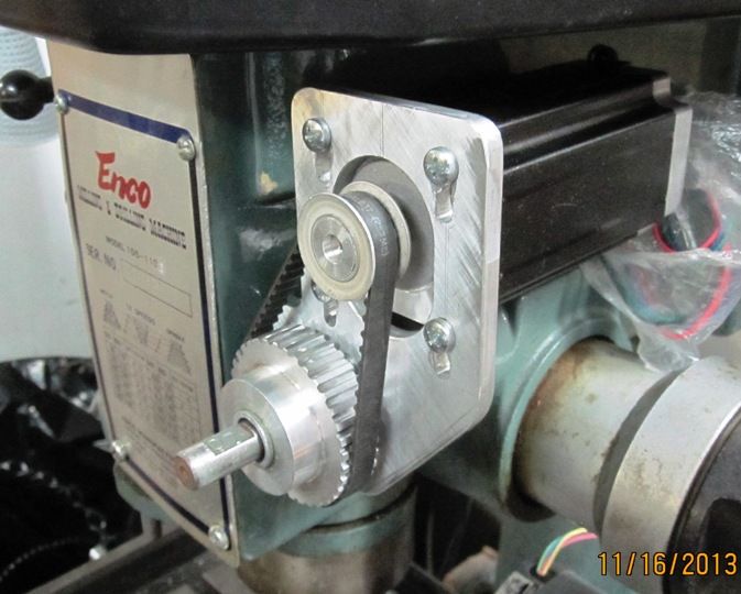
Now if I can just get as good a job done on the X and Y axes, I'll be a happy camper!
Chuck
-
11-18-2013, 02:58 AM #24
Registered
- Join Date
- Dec 2006
- Posts
- 73
Moving on to the X-Axis. Here is 1/2 of the X-Axis motor mount. The ring will be split in half and drilled and tapped for two bolts to clamp around the bearing boss on the piece that bolts to the table, like an automotive connecting rod.

There will be a second piece made from 1/4" thick aluminum plate that the motor attaches to. The part with the motor will attach with a single 3/8" bolt so that it can be rotated to adjust the tension on the belt.
Chuck
-
11-18-2013, 03:09 AM #25
Gold Member
- Join Date
- Mar 2004
- Posts
- 1806
Very innovative. Haven't seen one done like that before, but looks like it should work just fine:})
I like new ideas.Art
AKA Country Bubba (Older Than Dirt)
-
11-18-2013, 03:13 AM #26
Gold Member
- Join Date
- Mar 2004
- Posts
- 1806
Multiple post
Art
AKA Country Bubba (Older Than Dirt)
-
11-18-2013, 03:22 AM #27
Gold Member
- Join Date
- Mar 2004
- Posts
- 1806
multiple post
Art
AKA Country Bubba (Older Than Dirt)
-
11-18-2013, 06:14 AM #28
Registered
- Join Date
- Sep 2013
- Posts
- 88
Whats your struggle with FreeMill? I have also recently started to play with this. Originally Posted by cffellows
Initialy I got fooled by not loading it in 'FreeMill' and instead using the trial full version which wont let you POST.
-
11-18-2013, 06:31 AM #29
Registered
- Join Date
- Dec 2006
- Posts
- 73
Thanks, Bubba. Unfortunately, I'm not the originator of this idea. I got it from the Home Shop Machinist article on converting the RF-30 back in 1990. Originally Posted by Bubba
Chuck
-
11-18-2013, 06:32 AM #30
Registered
- Join Date
- Dec 2006
- Posts
- 73
I don't understand what you're saying? FreeMill is included in the trial version of Visual Mill. Are you saying there is a stand alone version of FreeMill? Originally Posted by migrusch
Chuck
-
11-20-2013, 12:00 AM #31
Registered
- Join Date
- Dec 2006
- Posts
- 73
Got the X-Axis motor bracket nearly finished. Here's the part that attaches to the mill table, with clamping screws drilled, tapped, and mounted.

And here it is with the motor attached.
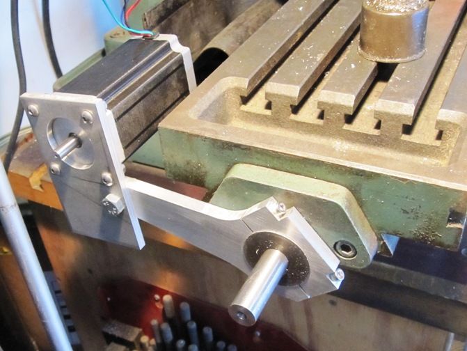
Will trim off the bottom part of the motor bracket later when I get closer to finished with the project.
Chuck
-
11-20-2013, 01:03 AM #32
Gold Member
- Join Date
- Jun 2004
- Posts
- 6618
Do you just use one of the bolts through the original bearing block for that arm? That is a pretty neat. Definitely different. I look forward to seeing the finished drive.
Lee
-
11-20-2013, 01:15 AM #33
Registered
- Join Date
- Dec 2006
- Posts
- 73
Both of the original bolts are used to secure the bearing block to the table. The arm is secured to the bearing block with the 2 SHCS clamping screws. By loosening the 2 clamping screws, the arm can be removed or rotated down to clear large work pieces on the table. Or it can be rotated up to clear the chip shield on the back of the table. The single, 3/8" bolt which clamps the motor to the arm lets the motor swivel to adjust belt tension. I was a little leary of that arrangement, but it seems plenty strong. There's not a lot of radial thrust with timing belts.
-
11-20-2013, 04:08 AM #34
Gold Member
- Join Date
- Feb 2006
- Posts
- 7063
I think you're going to find the single-bolt motor adjustment will move over time, or when you have a "crash"....
Regards,
Ray L.
-
11-20-2013, 11:06 PM #35
Registered
- Join Date
- Dec 2006
- Posts
- 73
So, moving with a "Crash" would be a good thing, right? Keep something else from breaking? As far as moving over time, it's easy enough to reposition and tighten, as long as I don't have to do it every 15 minutes. Originally Posted by SCzEngrgGroup
Chuck
-
11-20-2013, 11:14 PM #36
Gold Member
- Join Date
- Feb 2006
- Posts
- 7063
No, it won't do a thing to jeep anything from breaking in a crash, because the crash will already have occurred by the time it moves. It's just one additional thing that will have to be corrected after the crash. Besides, if it only moves a little, you'll end up with backlash, perhaps a lot, but you won't know it until your parts starts coming out screwed up. Far better to design to deal gracefully with worst-case conditions in the first place..... Originally Posted by cffellows
Regards,
Ray L.
-
11-20-2013, 11:23 PM #37
Gold Member
- Join Date
- Mar 2004
- Posts
- 1806
I look at my timing belt as a "fuse" that will pop if things get to radical (yep, I have popped one) and save the hardware from major breakage. I would much rather break a $3.00 belt than tear up a $100 servo motor or worse!
Art
AKA Country Bubba (Older Than Dirt)
-
11-20-2013, 11:41 PM #38
Registered
- Join Date
- Sep 2013
- Posts
- 88
The torque applied to the joint has little to do with the type of drive belt. Originally Posted by cffellows
The static tension in the belt might be low, but torque applied by the motor creates tension in the belt that acts around the bolt.
From the pictures you would expect a torque several times that of the stepper rating.
Having said that, if you apply sufficient torque to the bolt it will be ok.....
Sent from my GT-I9100T using Tapatalk
-
11-20-2013, 11:43 PM #39
Gold Member
- Join Date
- Jun 2004
- Posts
- 6618
That is why I asked, because I saw the possibility of swivel on the bracket. Fine if it only occurs intentionally, but not cool if it happens without you knowing about it. Still interested in seeing it completed. I may cnc mine one day if I don't sell it first. It is for sale locally though through word of mouth. Everyone comments, "you mean it's a manual mill with the hand wheels on it? Yes. You ain't gonna get that size cnc mill that has 10 minutes of run time on it for $500.00.
 Lee
Lee
-
11-20-2013, 11:46 PM #40
Gold Member
- Join Date
- Jun 2004
- Posts
- 6618
Originally Posted by migrusch
Also an additional adjustment bolt could be added easy enough that puts pressure on the motor mount at some point. In that case a single large bolt is very usable.Lee

 Reply With Quote
Similar Threads
-
Rong Fu reverse conversion
By kevrongfu in forum Benchtop MachinesReplies: 6Last Post: 12-13-2013, 12:58 PM -
starting rf30 conversion
By jbors in forum Benchtop MachinesReplies: 0Last Post: 12-08-2013, 05:38 PM -
rong fu 30 mill cnc conversion help
By kiyoukan in forum Uncategorised MetalWorking MachinesReplies: 3Last Post: 02-08-2012, 08:09 AM -
Rong Fu RF 45 CNC Conversion
By JackSmith in forum Knee Vertical MillsReplies: 15Last Post: 02-06-2011, 06:21 PM -
RONG FU RF-31 Conversion Servo or Stepper
By rpcaster in forum Knee Vertical MillsReplies: 2Last Post: 04-26-2007, 03:09 AM
