


Hi all. Let me just say that it’s an awesome forum and it inspired me to try and build my first CNC router.
At this point mechanics are built and I started experimenting with electronics. The issue I encountered that while trying to run motor in MDI mode with no load (motor not even connected to drive shaft yet) after turning normally for couple seconds all of the sudden it would stall and start stutter turning about 1 degree at a time. If I release the button on keyboard it would immediately turn normally and stop. The worst is happening if I try to move it via code (i.e. G0 Z10.0000). It immediately goes into stall/stutter mode and I have to manually reset it or risk burning the motor. In both cases axis distance counter in Mach3 displays movement as nothing happens (I understand it’s one way communication and it has no feedback from motor/driver on distance traveled. Just trying to be thorough). I tried it with all 3 motors and they all behave similarly. Also when it actually runs, the motors are very hot to touch, not sure if it’s related.
I’m pretty good with mechanical part of the machine but it’s microelectronics that always gives me headaches and that’s why I decided to start with small and cheap machine to learn on it. At this point I’m pretty stuck and hopeful that some of the pro’s here can show me the light
Here is what I have in electronics:
Power supply: Potrans FS-15024-1M 24V 6.5A
Motors: 57BYGH213 6.2V 1A http://www.mpja.com/download/57byghseries311.pdf
Controller: TB6560 3-Axis CNC 3 Axis TB6560 3.5A Stepping Motor Driver Controller | eBay
Computer: Old Celeron 633 512Mb RAM running Mach3 EVALUATION version
Motor is a 6-wire and is connected to the driver as follow (maybe it’s wrong but that how I read the diagram and it’s the only combination that worked for me):
ZA+ = Yellow
ZA- = Black
ZB+ = Green
ZB- = Red
White and Black wires are not connected to anything.
I followed the configuration instructions that came with controller and set all the flags in Mach3 according to them (Ports and Pins config, Motor output, etc). I run Driver test that came with Mach3 and it always shown “Excellent” status (this tells me not to blame old PC).
Sorry for the long post, I’ll try to keep it shorter as I gain more experience…
Results 1 to 13 of 13
-
09-24-2011, 02:59 AM #1
 Registered
- Join Date
- Sep 2011
- Posts
- 0
Stepper motors stall, stutter with no load
-
09-24-2011, 03:46 AM #2
Registered
- Join Date
- Jul 2011
- Posts
- 0
I fear, this motor driver board requires at least 2A motor. Your motors do only 1A.
Also, if you connect only half the coil on each phase, than you should have connected Red, White and Yellow, Black.
Hope, my manual helps a bit more: http://www.steering-inc.com/cncmanual.pdf
-
09-24-2011, 04:52 AM #3
Gold Member
- Join Date
- Jan 2010
- Posts
- 2141
I agree that your motors are not well matched to your driver board.
You may be able to use the full windings (as you evidently are doing now) instead of using half windings (as was suggested), but neither choice will correct that essential mismatch. (I believe that you meant to write that you are using the Yellow and Blue wires, and not the Yellow and Black wires.)
If you have experience using a soldering iron, you may be able to either replace the 6 precision current-setting resistors on that board, or possibly double them up by wiring additional resistors in parallel with the existing ones, in order to arrive at the proper resistance value to set the TB6560's current limits at 1.0 A.
(I have a version of that board that is supposedly set up to handle 1.0 A motors, however based on my interpretation of the current setting resistor value formula in the TB6560AHQ data sheet, the current setting associated with those resistor values comes out to be 2.0 A instead of 1.0 A, and so I'm not sure whether my calculation was incorrect or whether the board manufacturer's current rating spec for my board was incorrect. Either way, I'm a little bit reluctant to tell you what value resistor to use. IIRC, though, that value on my board is 0.22 ohms. You should be able to find a precision resistor color code decoding web page that will help you to figure out what value resistors your board currently has.)
Depending on the way that you have your DIP switches set (for the % of maximum current), it is possible that you could get some better results from your board as it is, but there are no guarantees.
Also note that some steppers may have a tendency to jitter or vibrate in place or otherwise fail to rotate properly if they have no load attached (other than the motor's own shaft), especially if the driver is set to a high microstepping mode.
One more note - those motors have a fairly high inductance, and so I'm not even sure whether the low voltage that you're running them at will build up the current properly.
(I hope that makes some kind of sense...)
-
09-24-2011, 01:46 PM #4
Registered
- Join Date
- Jul 2011
- Posts
- 0
Magnets don't like too much heat and there is a good chance, that the motors have gone bad. Yes, you can change the current resistor and you can use all four coils, leaving the center wire unattended, but the motors may do only 50%, if at all.
-
09-24-2011, 04:07 PM #5
Registered
- Join Date
- Sep 2011
- Posts
- 0
Thanks, guys. The controller link i gave you was not from the same seller. I remember specifically asking for 1A board when ordering mine. What and where exactly should i look to determine if my board supports 1A motors? (I'm comfortable with soldering as a process but not very strong with electronics themselves and calculations around it) Also, is it better to use full windings vs half as suggested by stewi? Doorknob - what would be the settings on DIP switches to try?
Appreciate you help guys.
-
09-24-2011, 04:56 PM #6
Registered
- Join Date
- Jul 2011
- Posts
- 0
There is indeed a 0.8-3 A board on the market, but I wouldn't trust the vendor a bit.
From the 6 dip switches, the first two should be off for lowest current. 3 and 4 can be on for fast buffer and I would set 5 on, 6 off for 1/2 step mode.
If you use both coils, then you have a higher inductance (force), which likely comes with lower speed.
I don't want to be negative, but it is very likely that your motors don't do anymore.
-
09-24-2011, 05:44 PM #7
Registered
- Join Date
- Jul 2011
- Posts
- 0
I have that same board and it gives me a fit everytime I try to run at 1/2 step. May not be your problem but i would be curious what it does at 1/8 step. I also had a bear of a time getting it set up. I never did get my z axis to work with Mach3. I am using kcam. You might try them on y and x if you havent already done so. I'll try to find my setup sheet that I got to work. The one that was sent with the board didn't work. I think enable on z and step on y had to be inverted signal.
-
09-24-2011, 07:15 PM #8
Gold Member
- Join Date
- Jan 2010
- Posts
- 2141
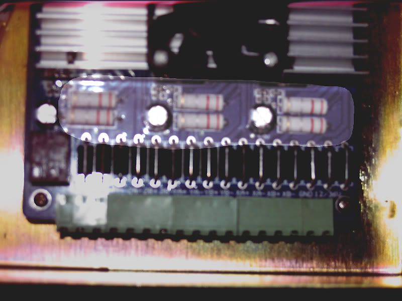
I will post a photo later this afternoon showing the resistors that set the maximum winding current. Originally Posted by stank

On my board (which was advertised as having a 1.0 A max current rating), the resistor values are 0.22 ohms. The resistors on my board have a 4-band color code of Red, Red, Silver, Gold. Some of the boards may have resistors with a 5-band color code.
There is a guide to reading resistor color codes at: How to read resistor color codes
As I mentioned earlier, my interpretation of the current setting resistor value formula in the TB6560AHQ datasheet would lead me to believe that a 0.22 ohm resistor would give a maximum current rating of 2.0A, instead of 1.0A. So I can't be certain of what the real value is supposed to be. But if your board's resistors have a value of 0.22 ohms, then at least you will know that your board is set up identically to mine (which is claimed to have a 1.0A maximum rating). If that's the case, then I would first try operating it with the DIP switch set to 50% current, and then see how it functions with the switch set to 100% current.
The half-winding recommendation by stewi makes sense to me. Originally Posted by stank
OK, here is a really poor cellphone camera-style image of my board, with the current setting resistors highlighted:
-
09-24-2011, 09:33 PM #9
Registered
- Join Date
- Sep 2011
- Posts
- 0
ok, now something start making sense to me:
Doorknob - thanks a bunch for the photo - mine has identical setup red-red-silver-gold.
Stewi - I compared your doc with the one that came with my card and Mach3 pin settings are different.
djbillyd007 - appreciate if you can find your settings, i had no problems with Z-axis in Mach3 (that's the one i'm actually playing with and using Y-axis as compare).
So, for now my plan of actions are;
1. Rewire motor as suggested by stewi
2. Mount motors to eliminate vibration
3. Try changing settings on DIP switches
4. Try changing configs on Mach3 as per stewi doc.
I'll keep it posted on any changes, thanks again for the help and direction!
-
09-25-2011, 02:09 AM #10
Community Moderator
- Join Date
- Mar 2003
- Posts
- 35538
I don't think it's part of this problem, but your PC is well below the minimum requirements of Mach3, which is 1Ghz.
Gerry
UCCNC 2017 Screenset
http://www.thecncwoodworker.com/2017.html
Mach3 2010 Screenset
http://www.thecncwoodworker.com/2010.html
JointCAM - CNC Dovetails & Box Joints
http://www.g-forcecnc.com/jointcam.html
(Note: The opinions expressed in this post are my own and are not necessarily those of CNCzone and its management)
-
09-26-2011, 03:36 AM #11
Registered
- Join Date
- Sep 2011
- Posts
- 0
You guys rock!
After rewiring motor, changing DIP switch configuration, and setting the “motor tuning and setup” parameters to match once in stewi’s doc it finally started hamming alone as supposed to!!! And motor runs ice cold!
I do feel a jog (? Not sure how to explain it, it feels like it’s trying to stall, makes a gurgling noise but then keeps going) once in a while and it lasts less then a second, I think it’ll bite me later on precision testing, but I’m happy for now.
DIP switch call was right on money – tried setting it back to On and motor start running rough and noisy right away…
Next I need to figure out calculation for 5/16-18 rod that I’m using (remember cheap) and see what precision I can get out of it.
Not holding my breath for super performance as it’s a test (cheap) machine, I’ll probably use it to actually manufacture pieces for “real” CNC machine but for now I managed to keep this whole build under $200…
Thanks for all the help, I’m sure it’s not the last snag I hit on this journey.
-
09-26-2011, 03:56 AM #12
Registered
- Join Date
- Jul 2011
- Posts
- 0
Originally Posted by stank
Glad to hear you got it. I built mine as cheap as possible also. I ended up coming in around $200. i was amazed after i got the bugs worked out how quick I was making things and how acurate it actually. I had my z on a 1/2 13 and it held up pretty well.
-
09-26-2011, 01:48 PM #13
Registered
- Join Date
- Jul 2011
- Posts
- 0
Glad to hear too. The gurgling noise sounds like your motors are loosing steps. This could very well be related to the PC's clock speed not meeting 1 GHz requirement as ger21 suggested. You may also want to check how much extra torque you have in your motors while they run at full speed.


 Reply With Quote
Similar Threads
-
max 60 ipm before motors stall?!
By bikedude987 in forum Automation Technology ProductsReplies: 6Last Post: 06-13-2011, 11:25 PM -
Stepper stutter issues resolved
By pencilneck in forum DIY CNC Router Table MachinesReplies: 2Last Post: 10-14-2010, 01:13 PM -
Stepper motor stall warning? Also EMC questions.
By borne2fly in forum Tormach Personal CNC MillReplies: 9Last Post: 03-08-2010, 08:18 AM -
Stepper stall
By ez-cnc.com in forum Stepper Motors / DrivesReplies: 7Last Post: 12-24-2006, 04:10 AM -
Need help with stepper stall
By orbyog in forum Stepper Motors / DrivesReplies: 10Last Post: 03-19-2006, 10:54 PM
