


All,
Sometime ago, I finished my X1-based mini-VMC. It works pretty well, but it's painfully slow, although I did pocket a 2.25"x2.25"x0.325" with a 1/2" endmill in about an hour today....
Anyway, I've been looking at getting a larger mill, such as a RF45 or an X3, but I realized today that I might have all the parts to actually build a bigger machine. I know, I know, it's probably easier to get an RF45 and go from there, but I have some pretty good bits laying around. The problem is that they are not quite perfect for this application.
What I have is a bunch of parts that used to be a pick and place machine. This thing had a cast iron X-axis with two linear rails and a ball screw coupled to a servo. The whole assembly (minus the cast iron feet, which were bolted on) weighs around 150 lbs and is all cast iron, including the saddle. It was mounted in a gantry arrangement, but the cast iron base is actually machined on all sides (that was my AHA moment when I realized this...). Pictures below (sorry for the crap pictures, only had a video camera handy).


So far, so good. What used to be the Y-axis (and hung perpendicularly on the X) is a combination of two linear rails, a ballscrew, an aluminum casting and some machined steel beams. It was mounted to the X via a large cast iron angle. Pics below.


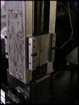

Both of these linear 'stages' have limit and home switches. These are mounted on a really cool dovetail track (see pic below).


These two bit would seem to be a great basis to DIY a larger CNC machine, but, there is a problem. The old X would be perfect for a Y-axis, as it's really heavy, but it's got 24 inches of travel, which seems excessive.... The old Y, I was thinking of using as a Z, but it's not really stiff enough, so I'd mount it to some MIC6 cast aluminum plate I've got (in 1" thickness), which would then be mounted to a large steel square column (filled with epoxy-granite), I think. It would look sorta like this:

I'm not really sure about this arrangement. It seems that a lot of the travel is just wasted in the Y, but I've never seen a bed mill where the X is the "bottom" part of the assembly. Usually, it's the Y so the whole thing can be trammed properly, I think. I don't think it's feasible to use the large cast iron bit as the Z, as the saddle is really heavy without a spindle or motor...
For the rest of the build, I'd probably use MIC6 since I've got a lot of it around. I'm thinking of having a welded steel support frame filled with epoxy+sand (which I used successfully in my X1) and a plate steel 'tub' that the base would be attached to (then backfilled with epoxy_sand), with MIC6 plates embedded to facilitate precise alignment, such as the base to column interface.
For the X, I'd follow what a lot of recent builders have done, and mount the rails on long supports with the bearing blocks on the table. Still gotta find a table...
Thoughts?
Thx.
Chris.
Thread: New build, layout questions
Results 1 to 1 of 1
-
12-28-2007, 10:45 AM #1
 Too many projects
- Join Date
- Jun 2006
- Posts
- 259
New build, layout questions
List of parts sources for CNC builders - http://www.CNCsources.net
Dyna Mechtronics 4400C Conversion - CNC bed mill w/toolchanger to Mach3 conversion - http://www.cnczone.com/forums/showthread.php?t=50787

 Reply With Quote
Similar Threads
-
JGRO questions/Build
By u77171 in forum Commercial CNC Wood RoutersReplies: 5Last Post: 01-23-2008, 05:44 AM -
jgro build questions
By cute_dorkie in forum Commercial CNC Wood RoutersReplies: 3Last Post: 10-14-2007, 06:11 AM -
Steel C-channel Build - Questions and pictures
By olskool in forum DIY CNC Router Table MachinesReplies: 10Last Post: 07-07-2007, 07:31 AM -
i want to build a machine but i have some questions?
By boostedbastard in forum Uncategorised MetalWorking MachinesReplies: 8Last Post: 05-15-2007, 05:40 PM -
El-Cheapo build questions
By musicmkr in forum DIY CNC Router Table MachinesReplies: 1Last Post: 06-11-2004, 09:35 PM
