


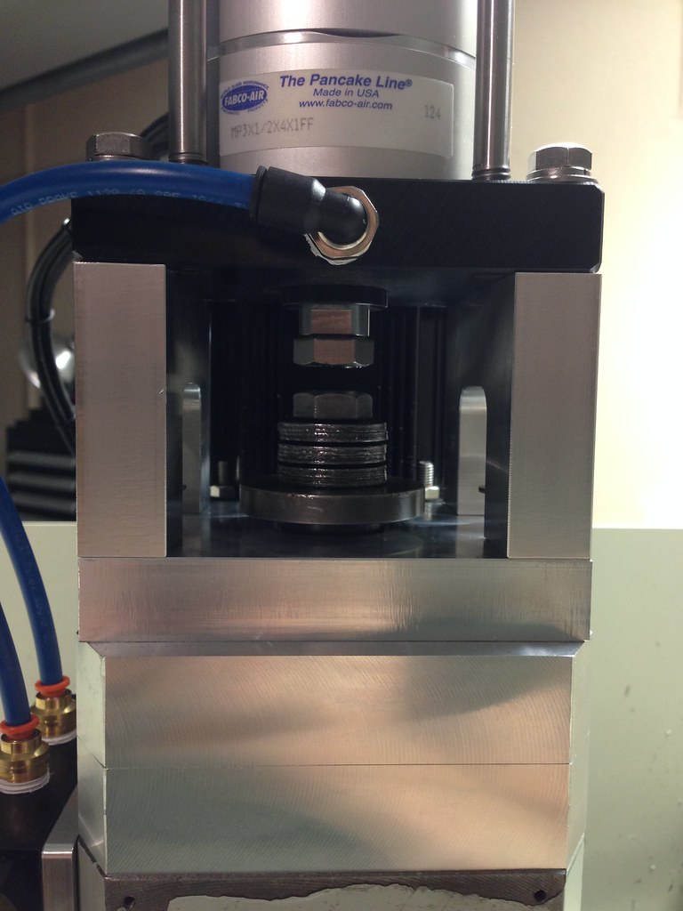
Well this was a test of the o rings and capturing the bellevilles. Most likely will make it out of steel and smaller.Attachment 298794
Sent from my iPhone using Tapatalk
Thread: Graham's Optimum BF20 Build
Results 141 to 160 of 192
-
11-23-2015, 04:05 PM #141
 Gold Member

- Join Date
- Nov 2009
- Posts
- 4415
Re: Graham's Optimum BF20 Build
A lazy man does it twice.
-
11-23-2015, 04:33 PM #142
Registered
- Join Date
- Aug 2008
- Posts
- 1186
Re: Graham's Optimum BF20 Build
Does it work as you hoped? Do the bellvilles bind in the new centering bore of the top hat? I played with a few designs a while back and considered putting orings around the edges of the bellvilles to allow them to expand and slide in the bore with some grease lubrication.
Curious to hear your results. I like the orings on the top hat lower edge to keep vibrations down.
Sent from my XT1080 using Tapatalk
-
11-23-2015, 08:44 PM #143
Gold Member
- Join Date
- Nov 2009
- Posts
- 4415
Re: Graham's Optimum BF20 Build
The O rings work great at eliminating the rattle. Not sure about the captured bellevilles as I haven't connected the cylinder. Or remade the bracketry needed yet.
Sent from my iPhone using TapatalkA lazy man does it twice.
-
11-24-2015, 06:50 AM #144
Registered
- Join Date
- Nov 2012
- Posts
- 220
Re: Graham's Optimum BF20 Build
Looks good Fastest:cheers: I have the same setup with the O-rings on my top hat. I really like it. Like you said, it eliminates the rattle and runs smoother. The only thing I need to get rid of now is the vibration caused by the belt at high rpm. I was thinking about making an idler/tensioner which would push against the belt to cut down on the vibration. Originally Posted by Fastest1

-
11-24-2015, 05:34 PM #145
Gold Member
- Join Date
- Nov 2009
- Posts
- 4415
Re: Graham's Optimum BF20 Build
That was kind of my intent on capturing and or attempting to center the belleville's in the tophat.
I do notice with each change of speed in the spindle adjusting the belt tension seems to help quell the vibration. As in many things, tighter isnt always better. Plenty of room for humor in that ;-)A lazy man does it twice.
-
12-15-2015, 05:19 AM #146
Registered
- Join Date
- Nov 2012
- Posts
- 220
Re: Graham's Optimum BF20 Build
Is anyone on here interested in selling me their LCD screen, hand controller (the pcb with the start, stop, forward, reverse, ect), and cable that came their BLDC spindle motor they got from Automation Technology? PM me if you are.
See link for what I am talking about:
http://www.automationtechnologiesinc...tor-and-driver
-
01-05-2016, 02:23 AM #147
Registered
- Join Date
- Nov 2012
- Posts
- 220
Re: Graham's Optimum BF20 Build
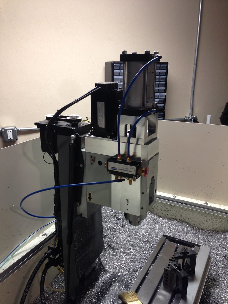
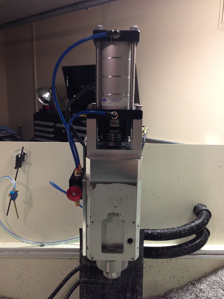
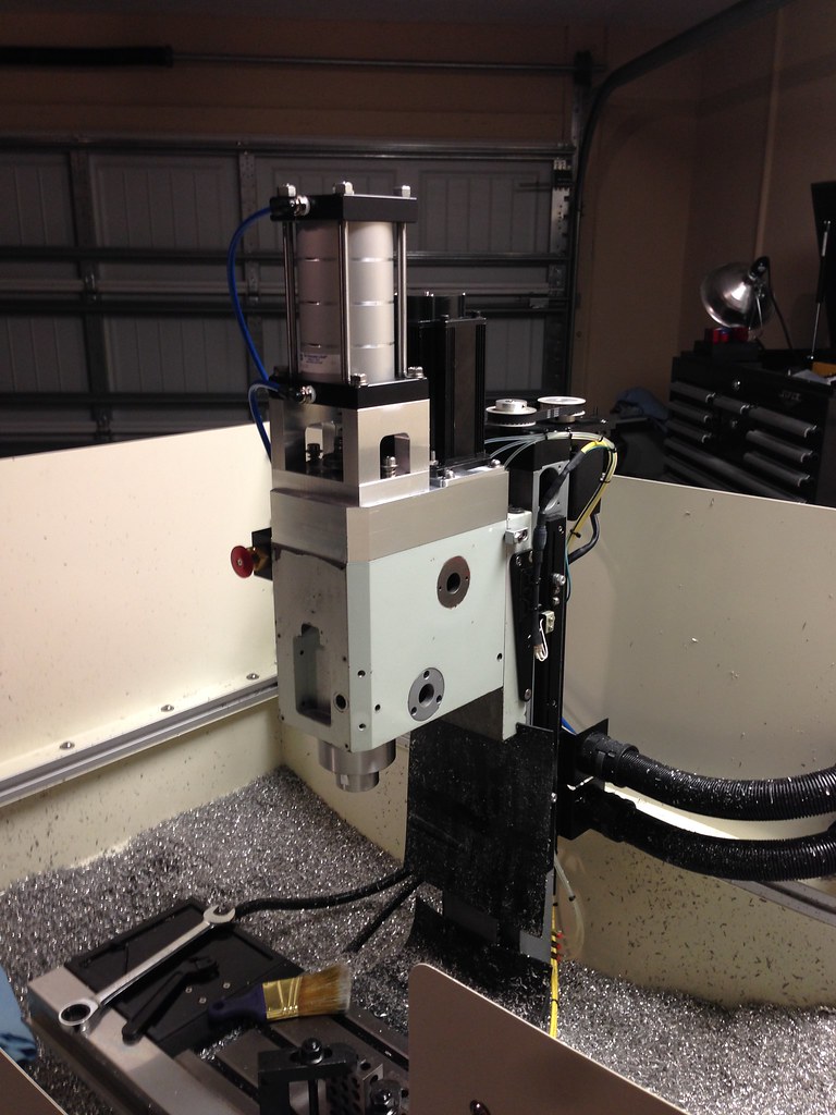
Today was a good day. I finally got my draw bar installed and working. Scott at Benchtop Precision made the draw bar for me out of a McMaster 1/2 inch bolt. My lathe is down, so I could not make it myself. I oversized the draw bar by about .003 and then sanded and lapped it into the top hat so it fits concentrically with no play. I also sized the OD of the draw bar so the Bellville washers fit snugly, so they stay concentric as well. Here are some pictures of everything installed. I also linked a video I posted on YouTube of it in action. I will black anodize everything in a few weeks after I finish making some more parts.
-
01-05-2016, 02:45 AM #148
Registered
- Join Date
- Aug 2008
- Posts
- 1186
Re: Graham's Optimum BF20 Build
Looks good!!
Sent from my XT1080 using Tapatalk
-
01-05-2016, 02:58 AM #149
Registered
- Join Date
- Nov 2012
- Posts
- 220
Re: Graham's Optimum BF20 Build
Thanks man! It has been a long time coming. Originally Posted by lcvette
-
01-05-2016, 03:08 AM #150
Registered
- Join Date
- Aug 2008
- Posts
- 1186
Re: Graham's Optimum BF20 Build
When you get your Lathe back up and running you can turn down the OD of those belvilles and make them nice and Shiny and parallel.. lol
Sent from my XT1080 using Tapatalk
-
01-05-2016, 03:16 AM #151
Neuer Benutzer
- Join Date
- Jan 2013
- Posts
- 630
Re: Graham's Optimum BF20 Build
Good to see piles of chips in the pan.
-
01-05-2016, 04:48 AM #152
Registered
- Join Date
- Nov 2012
- Posts
- 220
Re: Graham's Optimum BF20 Build
The mill is running well now:cheers: Originally Posted by Kenny Duval
-
01-05-2016, 05:54 AM #153
Member
- Join Date
- Oct 2008
- Posts
- 1641
Re: Graham's Optimum BF20 Build
Looks really good. Don't make the spring washers fit too snug to the draw bar. They are cup shaped now and when you flatten them out they will change size and you want to account for that. I believe McMaster and others have the sprung and unsprung dimensions on their site.
-
01-13-2016, 04:25 AM #154
Registered
- Join Date
- Nov 2012
- Posts
- 174
Re: Graham's Optimum BF20 Build
Graham, hadn't checked back in a while-the mill looks really great, nice to see it all working. --md
-
01-25-2016, 04:24 AM #155
Registered
- Join Date
- Nov 2012
- Posts
- 220
Re: Graham's Optimum BF20 Build
Thanks rwskinner:cheers: Your build is damn awesome. That is a good point about the washers. I took that into account. I sized everything based off of the min ID of the washers. It appears to be working well, but I have not done any heavy cutting so we shall see. I have some heavier washers on standby if I get tool pullout. If I have to switch to the heavier washers I will need to make something to go around the OD of the washers to keep them centered. The heavier washers have a larger ID. Originally Posted by rwskinner
-
01-25-2016, 04:26 AM #156
Registered
- Join Date
- Nov 2012
- Posts
- 220
Re: Graham's Optimum BF20 Build
Thanks mduckett! it is good to see you are back working on your build as well Originally Posted by mduckett

-
01-25-2016, 04:36 AM #157
Registered
- Join Date
- Nov 2012
- Posts
- 220
Re: Graham's Optimum BF20 Build
I am still tweaking the mill...can't seem to stop. I have a list of stuff I am trying to work off:
I am going to make the enclosure taller to keep the chips in
The x-axis sounds good in one direction and rough going in the other...not sure what that is about.
I still need to tweak the one shot oiling system. I am getting to much oil on the ball screws and not enough on the ways
I want to remake my gib strips. I did a messy job when I put the oil holes in them. Also, I am not a fan of the screws you use to tighten them. Might see if I can find/make something better.
I need to mount my spindle motor drive and wire it to my controller...that will take some head scratching.
After all that and assuming everything keeps working the mill should be done. I have spent so much time working on the mill I need to remember why I converted it in the first place...
-
01-25-2016, 06:25 PM #158
Registered
- Join Date
- Jul 2008
- Posts
- 44
Re: Graham's Optimum BF20 Build
Your build is looking awesome.
As to the oil to your ball screws / ways, you need a adjustable needle valve to control the flow to each component separately.
-
03-03-2016, 11:58 PM #159
Registered
- Join Date
- Jun 2010
- Posts
- 18
Originally Posted by gcofieldd
I know I'm a little late jumping in on this one - like 18 months or so too late - but the problem is most likely that you tried to tell HSM to give you both flood and mist cooling at the same time. For some reason Autodesk refuses to believe that you can put an M7 on one line and an M8 on the next line without somehow managing to blow up your mill. I have mist cooling set up at home, with a shop vac to suck away chips and fumes, and have to manually add in the M8, while HSM gives me the M7 automatically. I wish they'd let you do both.
-
05-22-2016, 07:09 PM #160
Registered
- Join Date
- Nov 2012
- Posts
- 220
Re: Graham's Optimum BF20 Build
I really dislike the mount/ mounting solution for the nozzle that comes with the FogBuster. I decided to modify it, so I bought a manifold, loc-line, and a couple push-to-connect fittings from McMaster-Carr to replaced the nozzle. My solution did not work as well as I had hoped. The new nozzle sputters and I have to open the coolant valve up all the way to get it to spray.
Does anyone who has made a DIY FogBuster have a solution for this?
Here are pictures of what I did:


 Reply With Quote
 There is at least an 1/8 inch bend in it--not sure how I missed that. I may wait on fixing it. It seems like it works ok, just a little rough going in the +x direction.
Similar Threads
-
my converted optimum bf20 cnc for sale
By 3barboost in forum South Africa Club HouseReplies: 0Last Post: 03-07-2014, 08:39 PM -
Yet another BF20 build by a noob
By crclark in forum Benchtop MachinesReplies: 21Last Post: 02-27-2012, 09:40 PM -
Optimum BF20 G0704 Conversion
By Winnfield in forum Benchtop MachinesReplies: 0Last Post: 08-07-2011, 12:16 AM -
Sieg KX3 or Optimum BF20? Need advice, please.
By anlmat in forum Uncategorised MetalWorking MachinesReplies: 2Last Post: 01-30-2011, 10:21 AM -
BF20 BALLSCREW OPTIMUM
By dfv in forum Uncategorised MetalWorking MachinesReplies: 0Last Post: 04-16-2010, 07:26 PM
