


What about the pulleys make you think there is a problem with the machining? The ones I have look ok to me. The only flaw I see is it looks like they had monkeys deburring the set screw holes but that's not going to affect anything.
Are you concerned with the tooth contact due to the load or backlash? From my calculation using MITCalc they shouldn't have a problem transferring the loads. I haven't read anything about tooth contact affecting backlash. There shouldn't be enough to worry about anyway, at least for what I plan to use it for.
I went ahead and ordered the 23ft of belt that I need this evening. Hold off on ordering yours if you want and I'll post some detailed pics of how well the belts mesh with the pulleys when it gets here. I cant say I'm a fan of a stacked gear reduction if you go with 18T pulleys. It would add to the cost, complexity, and if there is any backlash with the timing belts you'd have that much more introduced into your system.
I was curious so I started adding up what I've spent. The grand total came to $781.81 but that includes 3 extra stepper drivers, an extra 4' piece of 8020 I wont be using, and $166.22 in shipping charges to get everything to my door. If it wasn't for those 3 things the total would have only been $450. The shipping is what gets you, makes up ~21% of my total costs.
Results 21 to 40 of 62
-
02-23-2010, 07:24 AM #21
 Registered
- Join Date
- Nov 2009
- Posts
- 106
-
02-23-2010, 03:15 PM #22
Registered
- Join Date
- Apr 2007
- Posts
- 47
Yes I am concerned with the tooth contact being only 7, and if there is any gaps between belt teeth and pulley teeth I would think (only from reading about CNC machines) it would definately introduce backlash underload. And, Yes I think I might wait for your order to arrive. Did you order from Polybelt.com? I was just thinking this morning that it might be good idea to get a sample of L pitch belt and maybe throw in another pulley and belt to compare to the L pitch pulleys and belt before I make a big order. I was comparing the L pitch to the 25mm wide T10 pitch pulleys. It would only be around $20 bucks more to get the 25mm T10 pulley and belt than it would if I were to get 1" wide L pitch 12T pulleys and belt. Yeah the set screw holes are pretty cruddy, I'm just assuming that if they (who ever made these pulleys) didn't take the extra cautious effort to drill the setscrew holes better then maybe they did the same for the machining of the pulleys? I'm not saying they are, just assuming they "might be". But they could be plenty for what I wanna do and what you wanna do. I just have no idea being these are the first pulleys that I've ever bought.
One thing I keep remembering, comparing to yours, my X axis is going to be a bit longer. My linear slides are 54" long and I'm going to be putting the pulleys on the face and rear of the table. So I'm guessing my pulleys are going to be around 56"-58" apart, and I keep wondering how much force will it take before the 120" of 3/4" wide belt say stretches a 1/16". I'm sure when I'm cutting foam it won't stretch, but I really wanna cut thick wood (to make furniture) and carve wood aswell. but 90% of the time I'm gonna be cutting foam.
Thanks for pointing out the double backlash in the stacked reduction, I never thought of that.
-
02-23-2010, 05:23 PM #23
Registered
- Join Date
- Apr 2007
- Posts
- 47
Do you want to sell that 4' 8020 length? I think I wanna go that route for my Y axis.
-
02-23-2010, 08:39 PM #24
Registered
- Join Date
- Nov 2009
- Posts
- 106
Yes I ordered my belts from polytech, its about 1/4 the price there than over at sdp-si.
If you want that piece of 8020 I'll sell it to you for what I paid so around $25 +shipping. I got it from 8020 on ebay used, it has 45 degree cuts on both ends so you'll only have about 45" of usable length once you cut that off. There is also 2 holes drilled toward the center. Its 45S 4590 (45mm x90mm). I added a picture of it and a comparison of the more commonly used 1530. The 4590 works better for my design, its lighter by about .8lbs/ft according to the 8020 calculator and slightly stiffer although in the opposite directions which is actually better for how I'm using it. I also like it for my design because the center cavity is big enough to run one side of the 3/4" belt through.
-
02-23-2010, 09:19 PM #25
Registered
- Join Date
- Apr 2007
- Posts
- 47
Hmm..
I'm wondering now how much it would hold up to twisting? I would basically be using it on my gantry just like how it is setup on yours, the only difference there would be is that I'm gonna be bolting the SBR16 supported linear rails to the top and bottom. Thinking that it is only 45mm width, I wonder if it will twist under load when moving up and down the X axis when the router is in the center. I probably wouldn't care if the gantry was low to the table but I wanna make my gantry 6" - 10" above the table. With the the Z axis extended all the way down it will act like a lever and possibly twist that 8020.
-
02-23-2010, 10:21 PM #26
Registered
- Join Date
- Nov 2009
- Posts
- 106
I just did a rough simulation in solidworks with a torque of about 25 lb-ft and the max deflection of the beam was .04mm. That is with a distributed load and fixed ends, It would be more accurate if I used simply supported ends and point loading, but I'm not familiar with the solidworks simulation and I don't have ansys on this computer so I didn't bother trying to run a more accurate simulation. If you double that number to be safe, you'd see something like a half mm of deflection at the tip of the tool when its hanging 6" below the gantry, not taking into account any deflection from any other components. These are just really rough estimates if you're really concerned about the accuracy of your design you're going to have to do a lot more engineering than what I wanna do for my build, or just make everything bigger than it needs to be.
-
02-24-2010, 04:49 AM #27
Registered
- Join Date
- Apr 2007
- Posts
- 47
Yeah Lol Just go with something bigger. I would love to engineer it but it's going to be more of a "common sense design".
I have a hurricane rated glass exterior door laying outside of my garage that I pulled off a new house that was gonna be torn down. I was checking out the size and thickness of the aluminum frame that looks like extruded aluminum. It's probably 2" width x 6". Looks to be around an 1/8" thick aluminum. I wish I could take apart this door because it would be perfect aluminum stock for my gantry but this door looks brand new and is around a $500 door. I think I'm gonna go to a shop that makes exterior aluminum doors and see if I can get a length of aluminum. I know the door I have would be plenty strong for my gantry.
-
02-24-2010, 11:39 PM #28
Registered
- Join Date
- Nov 2009
- Posts
- 106
I guess going bigger is easier than doing the engineering, but it gets costly, bigger = more materials = more weight = stronger motors and drives......
I was playing around with simulationexpress in solidworks a little bit today. I ran a more accurate simulation on the 8020. I'm really not sure how much radial load is at the tool tip. I assumed 50lbs for the analysis with the tool 6in below the gantry so the applied moment on the 8020 is 25 ft-lbs. I also applied a load of 25lb to account for the weight of the z axis.
Here are the results, max deflection is .0074in.
-
02-25-2010, 12:19 AM #29
Registered
- Join Date
- Oct 2009
- Posts
- 272
Deflection Detection!!
stangtjk,
Does the 8020 for your Y-axis have a steel plate? And if so, is the steel plate accounted for in your simulation?
Randy,I may not be good....
But I am S L O W!!
-
02-25-2010, 12:50 AM #30
Registered
- Join Date
- Nov 2009
- Posts
- 106
No, there is no steel plate, however there are steel tracks that will be bolted to the top and bottom of the 8020 for the bearings which are basically heavy duty C-channel that should add a good bit of strength. They are not in the simulation because solidworks will only do an analysis on a single part.
-
02-25-2010, 01:08 AM #31
Registered
- Join Date
- Oct 2009
- Posts
- 272
 c-Channel vs. Plate steel
Is there a reason for chosing the c-channel over plate steel? Just curious.
I may not be good....
But I am S L O W!!
-
02-25-2010, 02:23 AM #32
Registered
- Join Date
- Nov 2009
- Posts
- 106
I didn't, its not exactly c-channel, its just the type of linear rail I'm using. Here is a picture of it.

-
02-25-2010, 02:46 AM #33
Registered
- Join Date
- Nov 2009
- Posts
- 106
It's pretty strong in itself. With a 25lb load applied to the center of the rail the deflection is only .01in in the z direction and .002in the x direction so I think with 2 of these rails along with the 8020 there wont be a whole lot of deflection on the gantry. Plenty strong enough for a wood router.
-
02-25-2010, 03:28 AM #34
Registered
- Join Date
- Nov 2009
- Posts
- 106
All those simulations were done with fixed ends rather than simply supported so the deflections will be a little more. I'm still learning the solidworks simulation stuff. Under SimulationExpress fixed ends is the only support option. I just realized that I had to enable solidworks simulation to be able to use simply supported ends, it will also allow simulation of multiple parts. I'll play around with it a little more. I'll have it figured out later tonight and come up with an accurate simulation. I'm really just doing this for learning purposes in solidworks, I'm pretty confident the design will be more than enough to carve some wood and foam.
-
02-25-2010, 04:40 AM #35
Registered
- Join Date
- Oct 2009
- Posts
- 272
Thanks for the answer regarding the linear rail (c-channel). It will be interesting to compare the simulation to your real life results.
I may not be good....
But I am S L O W!!
-
02-25-2010, 04:22 PM #36
Registered
- Join Date
- Nov 2009
- Posts
- 106
I think I've got solidworks simulation environment figured out now. I ran the beam with rails attached, this time the ends were simply supported rather than fixed and the the loads were applied over a length of 5" in the center of the beam which is about how long my bearing blocks are. With a 50lb load applied in the Z direction deflection was .00117", same load in the X resulted in a deflection of .0036". I also ran it once with a 50lb load in both directions along with a torque of 25ft-lbs and came up with a deflection of .0073"
If I end up with deflections in the neighborhood of .01" I'll be more than satisfied. I guess while I'm at it I might as well run simulations on the rest of the parts, I may get bored later and give it a shot.
I received the bearings that I'll be using for the shafts today, now all that's left are the belts. I'll probably start building next weekend. I'm going to using my family's shop which is about an hour and a half from my place so hopefully I can get most of it knocked out in one weekend.
On a random side note I've been having problems with the left click on my sidewinder mouse. I've been using it for over 2 years now and up until now its been great, I thought I was going to have to shell out $50-70 for a new one but I contacted Microsoft on Saturday and they sent me out a brand new one free of charge and I received it today.
-
02-25-2010, 06:10 PM #37
Registered
- Join Date
- Mar 2009
- Posts
- 624
Hi stangtjk,
Nice result with MS, i think there warranty/repair service is great, they have come good with me in the past too.
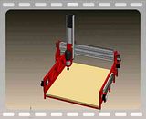
Your machine looks cool, like it very much. Great renderings as well, only thing that i can see that you dont show is how are the 2 sides connected together.?
I can tell you from my build that the side to side movement from the mass of the Zaxis moving across the gantry can be felt in the base of the machine.
So any weakness will be highlighted sooner or later.
I you can i would run some sims with the forces in this direction.? . . . . Which by the way i think is a cool feature to have, wish i'd had it when i drew mine!!
Cheers
Dean.
-
02-25-2010, 07:24 PM #38
Registered
- Join Date
- Nov 2009
- Posts
- 106
You cant see it, but in that last render showing the mdf spoilboard there is a metal structure of angle iron underneath supporting the table and tying the two sides together. I'll probably add a piece of tubing across the front and back of the machine as well or at least gussets on each corner if I decide the tube will get in the way. I ran a simulation on the gantry uprights as if you were pushing on it from the side (I think thats what you were meaning?), with a 50lb load the deflection was .004". I'll do the same study for the base of the machine next. I don't know why I keep using 50lbs it just seemed reasonable for cutting through wood. If anyone has a better idea of how much radial load is acting on a tool cutting into wood let me know.
edit: The base showed a deflection of .002", adding the .004" from the uprights gives a total deflection perpendicular to the x-axis of .006" with a 100lb force (50lbs distributed to each side of the gantry). Looking at the numbers you posted on that other thread this seems reasonable, my machine looks to be about half the size and has twice the deflection, makes sense. I'm not a machinist so these small numbers aren't as easy for me to grasp, I have to put it into terms I can relate with so .01" is about half the size of a piece of lead from a .5mm lead pencil. If I can get my machine to perform within those tolerances I'd be tickled.
-
02-25-2010, 08:50 PM #39
Registered
- Join Date
- Oct 2009
- Posts
- 272
 Peeping Tom!
stangtjk,
In your rush, out the door to the shop, remember to load ALL your neccessary tools, equipment and supplies. You may want to have a checklist of everything you MAY need. Just so you don't forget, a camera/camcorder is a must (of course, check the batteries). There are those of us here on the zone that must see pictures and video (machine p0rn).:devious:
On a more serious note, great job with the renders & simulations. Is the simultor able to simulate motion? It would be cool to see your machine in motion, even before it is "Built". I also hope some of the zone "experts" chime in regarding the actual forces involved, I'm sure others would also be curious.
Randy,I may not be good....
But I am S L O W!!
-
02-25-2010, 09:06 PM #40
Registered
- Join Date
- Nov 2009
- Posts
- 106
Solidworks has the ability to do motion simulations, however I don't. The way I have all the mates I can click and grab the router and move it around and see each axis moving together but when I tried to do a motion study it took forever to rebuild everything and some not so good stuff starting happening lol. I'm sure its because I didn't know what I was doing. I guess I could cheat and just record me dragging it around.
Edit: Ok I used FRAPS to take a video while dragging it around. Its going to take forever to upload but I'll share it when its done. I couldn't reliably drag all three axis at once without one going off the deep end so its just going to be 2 axis movement.
Edit: Finally uploaded, did this just for you Randy lol.

 Reply With Quote
Similar Threads
-
Design advice series offers technical insights
By igus in forum News AnnouncementsReplies: 0Last Post: 05-22-2009, 06:58 PM -
Design Advice Needed
By JeLC in forum DIY CNC Router Table MachinesReplies: 3Last Post: 03-03-2009, 05:39 AM -
Need advice with Z axis design
By isvflorin in forum DIY CNC Router Table MachinesReplies: 3Last Post: 01-09-2009, 01:47 PM -
Semi-newbie looking for some design advice
By galacticroot in forum DIY CNC Router Table MachinesReplies: 15Last Post: 08-24-2006, 12:49 PM -
design advice for a new builder
By deft in forum DIY CNC Router Table MachinesReplies: 9Last Post: 05-09-2003, 01:03 AM
