


Probably cost. I can only imagine how much money those monster steppers were, let alone servos!Originally Posted by 15mgtar

Thread: 5AXIS: photos - new build
Results 161 to 180 of 191
-
08-16-2010, 10:24 PM #161
 Gold Member
- Join Date
- Feb 2010
- Posts
- 3447
-
08-16-2010, 10:40 PM #162
Registered

- Join Date
- Feb 2010
- Posts
- 202
one stepper motor 50Nm - ~800$
-
08-17-2010, 05:48 PM #163
Registered
- Join Date
- Jan 2009
- Posts
- 396
how much is it to replace it with servo motor (what is the spec for servo)? and what gearing do you use on the rack n pinion? I'm really interested on building one someday
-
08-21-2010, 07:30 AM #164
Registered
- Join Date
- Feb 2010
- Posts
- 202

machines constructed by me
http://www.facebook.com/album.php?ai...00001079170477
-
08-21-2010, 04:10 PM #165
Registered
- Join Date
- Jan 2009
- Posts
- 396
very nice machines Bartuss1! I love the 5 axis one. btw how do you level and line up all those linear guides and ballscrews???
-
08-21-2010, 04:39 PM #166
Registered
- Join Date
- Feb 2010
- Posts
- 202
very easy
shows the example of the latest machines
http://picasaweb.google.pl/soltys.de...zarkaKopiarka#
-
08-22-2010, 07:33 PM #167
Registered
- Join Date
- Jan 2009
- Posts
- 396
now what if the the table isn't perfectly square and level??? how do you build your table that is totally flat and square? because for all I know that none square pipes are totally straight and event they have little difference in thickness and dimension.
-
08-22-2010, 07:48 PM #168
Registered
- Join Date
- Feb 2010
- Posts
- 202
it was welded on the grinding table, and it is the horizontal surface
-
08-23-2010, 03:06 AM #169
Registered
- Join Date
- Jan 2009
- Posts
- 396
I wish I can go to Poland and see master Bartuss at work!

But the those hollow steel isn't perfectly straight and have the same thickness do you need to grind it down to make it perfectly level and straight?
-
09-17-2010, 04:25 PM #170
Registered
- Join Date
- Feb 2010
- Posts
- 202
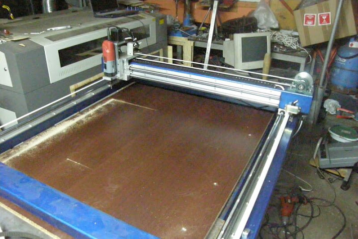
machine ready
http://picasaweb.google.pl/soltys.de...zarkaKopiarka#
time for another
-
09-17-2010, 05:17 PM #171
Registered
- Join Date
- Mar 2006
- Posts
- 489
Dosen't really look ready to me, unless it's manually controlled...
That's the strangest z-axis setup I've ever seen. Why did you go that way?
-
09-17-2010, 05:39 PM #172
Gold Member
- Join Date
- Feb 2010
- Posts
- 3447
very interesting! That right triangle must make a pretty rock solid Z axis. I also have never seen that. That is pretty cool.
-
09-17-2010, 07:17 PM #173
Registered
- Join Date
- Feb 2010
- Posts
- 202
it is manually, the client just wanted to working to copy the flasks guns.
Z-axis has a counterweight, very little work
-
09-24-2010, 02:05 PM #174
Registered
- Join Date
- Oct 2007
- Posts
- 123
Hi Bartuss
I have great admiration for your work! Nice stuff!
on that big 5 axis machine, did you have a brake or counterweight on the Z axis? or Does the self locking trap. screw do all the work? If so, the 50Nm stepper (that's about 7,000 oz-in) has to overcome the friction of the self lock as well? One more Q: What nema size are the frames are the 28 & 50Nm motors?
Just FYI if you're interested, I'm doing a 5 axis build here:
http://www.cnczone.com/forums/showthread.php?t=110480
& here:
http://www.calvinodesign.com/90037/9...01/BuildLog06/
I like the idea of the counterweight that you did with the red & blue machine.
I'm working on a way to keep position on the Z when power is off.
What do you think about a spring for the Z axis counterweight? Or a power-off brake?
Nice work man! Cheers!
-
10-18-2010, 08:25 PM #175
Registered
- Join Date
- Feb 2010
- Posts
- 202
new machine
Picasa Web Albums - Bartosz So
-
12-01-2010, 05:15 AM #176
Registered
- Join Date
- Nov 2010
- Posts
- 0
I am looking a trying to build a similar sized machine, but I have a few questions to ask. (ways=linear bearing)
1) What positional accuracy could you hold with this machine? .001" .010" or .100"?
2) How do you ensure the X axis ways are parrallel to each other. Considering they are so far away, wouldn't it take expensive equipment to get this tolerance to less than .010"?
3) How do you ensure X, Y, ans Z axes are perpindicular to each other? I know in more expensive machines a laser system is used, but I am wondering how one would do it on a budget.
4) Did you shim the ways when you mounted them to ensure that it would not be wavy? i.e. if what you bolt them to is wavy then they the machine wil be wavy unless you use shims or precision machining.
If you cant tell I am trying to figure out how you trued this machine without special equipment. If you have any advice it would be greatly appreciated
-
12-08-2010, 02:42 AM #177
Registered
- Join Date
- Mar 2004
- Posts
- 439
steigcm-
After spending 10+ years designing and building high precision gantry machines for silicon wafer and LCD production, you are correct, it usually takes lasers and other expensive equipment to get a machine true and accurate. However, if you have more time and patience than money, it can still be done.
Some tricks:
1.) Start with the "Main Rail" - and concentrate on getting it straight and flat. One of the least expensive ways to do that is by using an autocollimator. Sometimes they can be found for a good price on ebay. This will tell you angular error in two directions at the same time (pitch and yaw) of the bearing block as you move it over it's travel. Start from one end and work your way down. Alternately, you can look for a qualified straight edge or as large of a granite/cast iron surface plate as you can safely handle/position. Then, mount an indicator to the bearing block and indicate to the surface of the granite. You will need to set this up twice, as you can only measure straightness or flatness of one axis at a time. If your travel exceeds the length of the granite/cast iron, you can start at one end, and move the granite down the travel by about 1/2 the granite's length each time. That way you can use the first 1/2 the travel to realign the granite to the tightened rail, and the other half to align the rail.
2.) Add the second rail - You can mount an indicator on the "Main Rail" and use it to indicate in the second rail for both straightness and flatness - but they may be at different heights... One way to solve this would be to set up the granite surface plate in the middle of the machine, and use an indicator with a long reach to align the plane of the granite to the first rail. Then you can rotate the indicator across to the other rail and adjust it until it is the same height. Then use the main rail to align the second rail.
3.) Squaring up travels - once you have your machine assembled and under power, and each axis is straight and flat, you still don't know if they are square to each other. This is usually most easily accomplished with a large precision square, but diagonal measurements at the extremes of travel also works very well. Start with a small precision square to get you close in all directions - X/Y, X/Z and Y/Z. Otherwise, the cosine errors will really cause frustration! For a large router you could use a tape measure, but for a more accurate machine consider buying or making a crazy-long caliper extension. Enco - Guaranteed Lowest Prices on Machinery, Tools and Shop Supplies It's not the actual length of the diagonal measurement that is critical, but the difference between them. If you make a caliper extension, it does not have to be a precision length - again, it is the difference between the measurements that matters. Use trig to calculate how far out of square the axes are, and adjust from there. The easiest way to measure this would be to mount some material to the extremes of travel, drill some holes at the 4 extremes of travel and measure diagonally between the holes. It'll likely take a few iterations to get it right. You can also use this trick on more than just the X/Y travel - as long as you have some way of making a hole or precision mark you can measure to. You could use a temporary spindle, or you could simply mount a sharp point to scribe a surface and measure across the marks.
I hope this helps - These are the same procedures as are done with laser interferometers, just on a budget.
Let me know if you have additional questions.
KeithNEATman
Basic research is what I'm doing when I don't know what I'm doing. Wernher von Braun
-
12-08-2010, 05:48 PM #178
Gold Member
- Join Date
- Feb 2010
- Posts
- 3447
You need to do a full write up article on this!! This is pretty much amazing info!!! In my large machine im partially stumped on how to square it all up. This should prove helpful!! Check out the link to my build if you have time, it would greatly be appreciated!!
http://www.cnczone.com/forums/genera...*rebuild*.html
Thanks!
Originally Posted by NEATman
-
01-19-2011, 04:23 PM #179
Registered
- Join Date
- Feb 2010
- Posts
- 202
-
01-19-2011, 05:57 PM #180
Registered
- Join Date
- Dec 2010
- Posts
- 337
just caught this thread , holys""t nice machine..
you could always sleep in it if your girlfriends chuck you out

 Reply With Quote
Similar Threads
-
5aXis-USB-iso-BOB
By Yachaan in forum Open Source Controller BoardsReplies: 12Last Post: 09-20-2015, 05:48 PM -
Semi - DIY CNC Router / Mill Project Build (With photos)
By rescueweasel in forum CNC Wood Router Project LogReplies: 17Last Post: 08-30-2014, 06:21 PM -
5axis help
By BOATDUDEGUY in forum Mach Software (ArtSoft software)Replies: 7Last Post: 02-24-2014, 08:08 PM -
My CNC build-up with video and photos + everything a beginner should know
By dmoore in forum DIY CNC Router Table MachinesReplies: 22Last Post: 02-07-2008, 02:53 AM -
5axis Help
By jybute in forum Haas MillsReplies: 0Last Post: 11-22-2006, 03:10 PM
