


Could someone help with a sample thread mill program using Winmax conversational? I have never used a thread mill and since their not cheap I would rather not screw it up on the first part. The thread I'll be working on is M10 x 1.5 x .750
Thread: Sample thread mill program
Results 1 to 10 of 10
-
01-31-2010, 01:47 AM #1
 Registered
- Join Date
- Mar 2008
- Posts
- 175
Sample thread mill program
-
02-01-2010, 02:21 AM #2
Registered
- Join Date
- Jul 2007
- Posts
- 378
Hello
I was wondering if you could provide more input on your operation.
1. Tool type and size. Single point or multiple point? Tool brand and model number would be great.
2. Inside or outside threads?
3. Type of material?
I'll search the web and see what I can come up with.
Can you ask your tool supplier, or Hurco dealer for help. I believe the local Hurco dealer in your area is Applied Machine Solutions Inc.
Did you get you hex profile figured out?
glovebox20
-
02-01-2010, 04:03 AM #3
Registered
- Join Date
- Feb 2006
- Posts
- 175
Not sure what you mean by sample program ?
Just go into "helix milling"
and specify your coordinates.
For multiple turns you add the degrees and can go over 360 deg.
For 4 turns i.e. you would have 1440
"Lead" is pitch.
Suggestions
Leave X and Y end points blank
Use Z depth and sweep angle to control pitch (they must match !)
Be sure to feed cutter in/out BEFORE retracting ! (to prevent crashing into threads)
Repeat block for finish pass
This program uses "Cutter comp "
If i was doing a threaded hole, I would feed down the center, then X over to the pitch diameter, and then climb (mill) up (CCW) and out the hole
-
02-01-2010, 04:28 AM #4
Registered
- Join Date
- Feb 2006
- Posts
- 175
For threading a stud, using your example,
Major diam 10 mm (.394) height .750 pitch .0591
Minor diameter .308 ( I'm guessing)
I would start with tool at x= 1.0
Feed down to Z 0.0 (Top of part)
Move to X .154 ( half minor diameter)
Helix
X center 0.0
Y center 0.0
Radius .197
Lead .0591
CCW
Z depth (13 x .0591)= -.7693
Sweep ( 13 x 360) = 4680
Move X (clear) = 1.0
Retract Z home
Hope this helps
-
02-01-2010, 05:02 AM #5
Registered
- Join Date
- Mar 2008
- Posts
- 175
Tool is solid carbide multi point .360 DIA I did purchase a M14 due to the length of threads it will cut as I will be using this tool on another job later.
http://www.lakeshorecarbide.com/m14-...hreadmill.aspx
Cutting OD threads.
Material is 12L14
Rich- Is your example for use with a single point tool starting at the bottom of the thread and working up?
Is there a way to ramp in/out as suggested by the tool manufacture? I don't see anything in the Helix section that would do this. I'm guessing but with a multi-tooth cutter the sweep angle needs to be more than 360* to insure that the cutter blends out the tool radius, how much more is recommended? Also, since the cutter is still at the minor DIA at the end of the cut, will the control automatically use a clearing move in X or Y before retracting in Z?
Glove-box- I think I got the hex figured out thanks to your explanation and drawing it out in CAD for locations of the hex points which made more scene once I could visualize it.
It will be later in the week before I get a chance to run it, Need to build a fixture to hold the parts first when I get home from this trip.
Currently I have been doing the threading op on a gang tool lathe one at a time is fast at 40 seconds cycle time but I can't do anything else which is one of the reasons why I bought the mill. I know it will take longer per part but at least I not chained to the machine .
.
-
02-01-2010, 06:36 AM #6
Registered
- Join Date
- Feb 2006
- Posts
- 175
Dave
ERROR- ERROR
The previous post should have a CW move !
CCW is for internal threads
Also the start of the thread was at 3 o clock position
Rich- Is your example for use with a single point tool starting at the bottom of the thread and working up?
----Yes I was thinking of a single point cutter ( I make my own) and no, I was feeding down (to negative Z depth)
I'm guessing but with a multi-tooth cutter the sweep angle needs to be more than 360* to insure that the cutter blends out the tool radius, how much more is recommended?
--- You can slow the linear feed ( X1.0 to X .2) then move into the material straight ( X+ .154), then helix UP (CCW) for two + revolutions ( 900 sweep) which will put the cutter at (negative) x-.154 . Then move X -.4
Any overlap will work. the problem I see, is that the material will move from cutting forces and that demands a second pass in my opinion....but do not end where you start as you also observed !
Also, since the cutter is still at the minor DIA at the end of the cut, will the control automatically use a clearing move in X or Y before retracting in Z?
---No, NOT unless you give it the move ( i.e. x -.154 to -.4) in the next segment. It will crash otherwise
----Dave I have never used a Multi thread Tool on my Hurco which is at home.
I used them at work, but the work pieces were stout and did not flex (3" OD SS). For Male threads, I like to feed top down because of better rigidity(CW).
This is easy with single point.
For holes, I do the opposite because of chips !
Rich Is there a way to ramp in/out as suggested by the tool manufacture? I don't see anything in the Helix section that would do this.
----If you want to ramp in, you need to do a two segment helix
Say you start at 12 o clock and only go to 3 O clock .(90 deg)
Make the Center of the helix .100" to the left (X -.1) and increase your radius another .100" to .297.
Now your cutter will feed down and reach the same helix starting point from the previous segment,.... which you put as the next move.
this will allow the cutter to ramp in and down and may eliminate the full second pass ??
When you reach the 3 o clock point after the first pass, add a third helix segment using the same bigger radius and negative X and you will ramp out to 6 o clock
Rich
-
02-02-2010, 01:41 AM #7
Registered
- Join Date
- Jul 2007
- Posts
- 378
hello
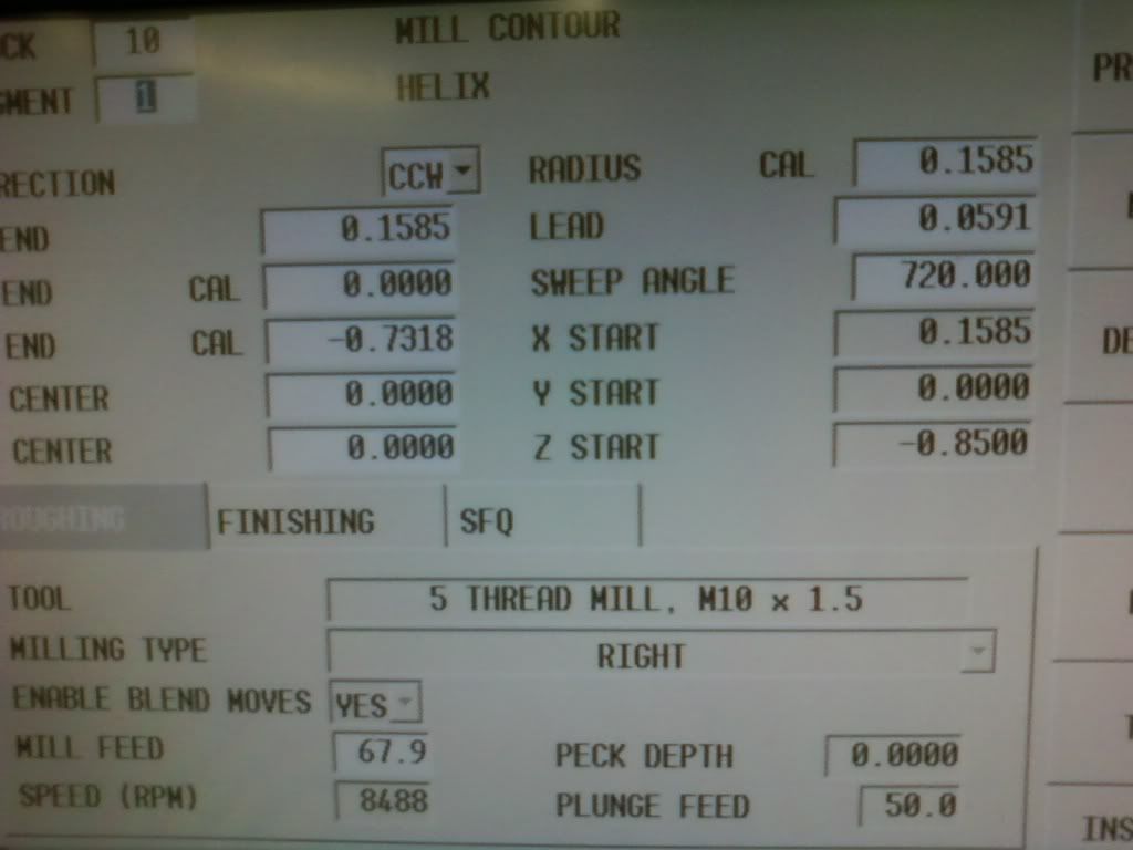
This is how I would thread mill your part
I will be arcing on the part with a 90' arc, mill around the part plus 5 degees (go past start point) while milling down, and arc off the the stud with 90' arc. I will be entering the stud on top (12 o'clock). part zero is center of part.
Use Milling Lines and Arcs "Cut Left"
Seg0 Xbk Ybk Z start -.7353 (% of sweep of arc in seg1 * pitch of thread [ex.25%*.05905=.0147] + total thread depth [-.750]), Z end (Same as Z Start) Peck: leave at Zero for no pecks!
Seg1 Mill helix CCW X0 Y.1606?(Minor Thread Dia/2) Zbk Xc0 Yc .6606? (minor Dia/2+ radius you want to arc in at) Radius .5 (Radius value you want to arc in) Lead -.0591 (thread pitch in inches) Sweep angle 90'(% of sweep*360')
Seg2 Mill Helix CW Xbk Ybk Zbk Xc0 Yc0 Radius (minor dia).1606 Lead (thread pitch in inches) -.0591 Sweep Angle 365
Seg3 Mill Helix CCW Xbk Ybk Zbk Xcbk Ycbk Raduis .5 (Radius value you want to arc out) Lead -.0591 (thread pitch in inches) Sweep angle 90'
Z end should be about -.8246"
bk=Value to be calculated by Winmax (Leave Blank)
Xc= Arc center
Yc= Arc center
May need to use "Recalculate End point/ Start point" if the Arcs don't start or end where you want them to.
Z Start can be at Z0 if you want the Feed down to your Z depth instead of Rapid down.Cation!! Retract clearance in program Parameters are calculated from the Z start point. If you want the tool to be .75 above your part before moving to the next part, you will have the add .75 + Z start position .7352 (convert negative Z start to a positive Value) = 1.4852" for retract clearance
Use "Pattern Locations" to mill the thread where you want it.
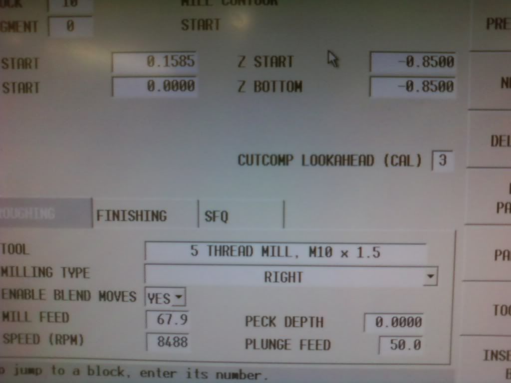
Speed and feeds
enter this in tool setup
SFM 350
Chip .003 per tooth
# of Flutes 4
(350*3.82)/.360=3714 RPM
3714*4*.003= 44 IPM (should be able to increase this to 75 IPM due to chip thinning)
I believe ALTiN coating might prefer to be ran dry in mild steel.
You may want to copy this block twice and adjust Seg1 Mill helix Y(Minor Thread Dia/2) to reduce "depth of cut" because pecking is not an option. Add .0252" (Y.1858) (Yc .6858) to the first block and .0126" (Y.1732) (Yc .6732) to the second block for the Seg1 Mill helix Y end value until you become more confident on how much the thread mill can cut.
To change the Minor Dia, you should only have to change the Seg1 Mill helix Y(Minor Thread Dia/2) dimension and Yc (minor Dia/2+ radius you arc in at) or your cutter dia. Whatever you prefer.
Not sure if this will work being I never thread milled myself. But at least You can get an idea on what the program may look like. My biggest concern is the Z lead on Seg1 & Seg3 and Radius (the Arc I use to lead in and out with) if the Z lead/radius is not set right, It may affect thread quality.
Quote
Also, since the cutter is still at the minor DIA at the end of the cut, will the control automatically use a clearing move in X or Y before retracting in Z?
---No, NOT unless you give it the move ( i.e. x -.154 to -.4) in the next segment. It will crash otherwise
Rich is correct!! Not only do you have to make sure the cutter is off the part before plunging (if it's not a plunge tool) you also have to make sure your off the part before raising the cutter as well. Also, You might want to change you Program parameters so the Z axis will not move up when the hit the Interrupt button or bad things can happen! Z cycle interrupt: NO! Z axis will stay down.
I used the info from the following sites to generate this program
http://www.sct-usa.com/millhelp.asp
http://www.lakeshorecarbide.com/m14-...hreadmill.aspx
http://www.lakeshorecarbide.com/lake...eedsfeeds.aspx
http://www.tribology-abc.com/calculators/metric-iso.htm
-
02-02-2010, 06:25 AM #8
Registered
- Join Date
- Jul 2007
- Posts
- 378
Just wanted to clear up the lead in & out moves a bit more.
On the older Ultimax control, It will calculate the blend in And out move when you Select mill circle, frame, & face. On the "face" function, it uses the cutter dia to calculate the lead in & out move. When using the Circle & Frame function, it uses the Blend overlap and Blend arc the the program parameters (milling tab). Just adjust these values and Graph your program to how it affects it. Blend overlap = how far the cutter will go past the start point before arcing off. Blend arc = size of radius it uses to blend off and on the part (from center of cutter).
The Ultimax control did not add the blend in & out move when using lines and arcs. Being a Ultimax user, I learned to do without by calculating my own Lead in and out moves. However, I believe the new Winmax control will allow you to add the blend in & out when milling lines and arcs. When selecting the Tool number for the block, there should e a drop down box for blend in/out with the choice yes/no. Selecting yes will add the blend moves similar to circles and frames. I prefer "no" but new users may prefer "yes" (default?). The Thread mill sample I provided you has it's own blend in & out move so be sure to select "no".
If you don't need the full 90' arc in/out, you should be able to adjust it easily in seg1 and seg3 in the sweep angle. Just make sure your Z end is the same as before in Seg1 before rerunning the programing or you may loose thread quality/depth. Also, if you do chose to use your thread mill to Rough & Finish in the same block, you can type a value in X&Y finish (program parameters, milling tab) but leave Z finish at Zero or thread quality may be degraded.
hope this clears it up
IF I'm wrong, someone please correct me.
glovebox20
-
03-10-2010, 10:56 AM #9
Registered
- Join Date
- Mar 2008
- Posts
- 175
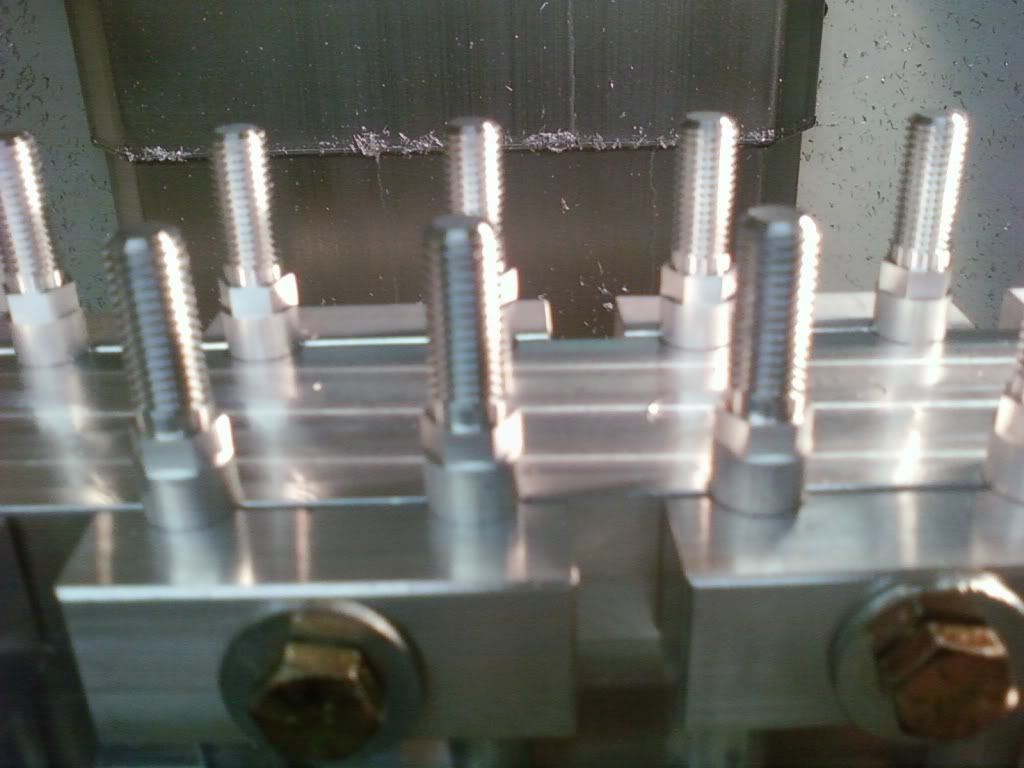
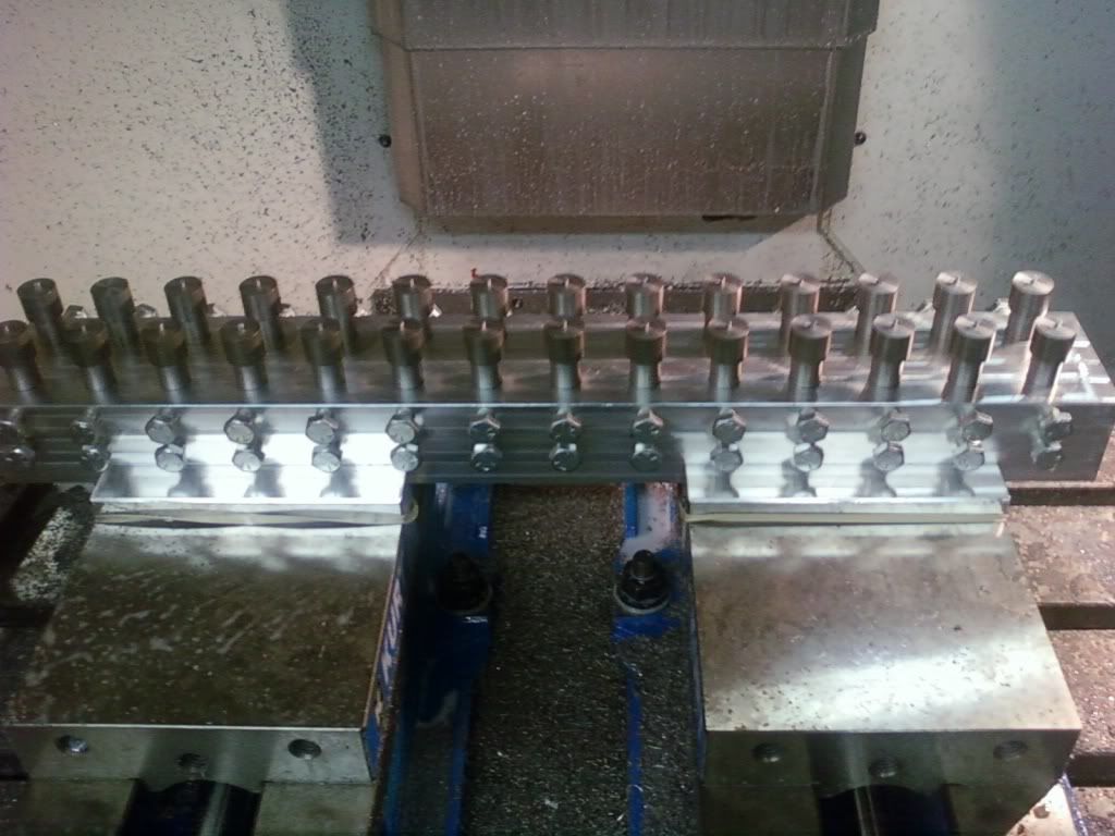
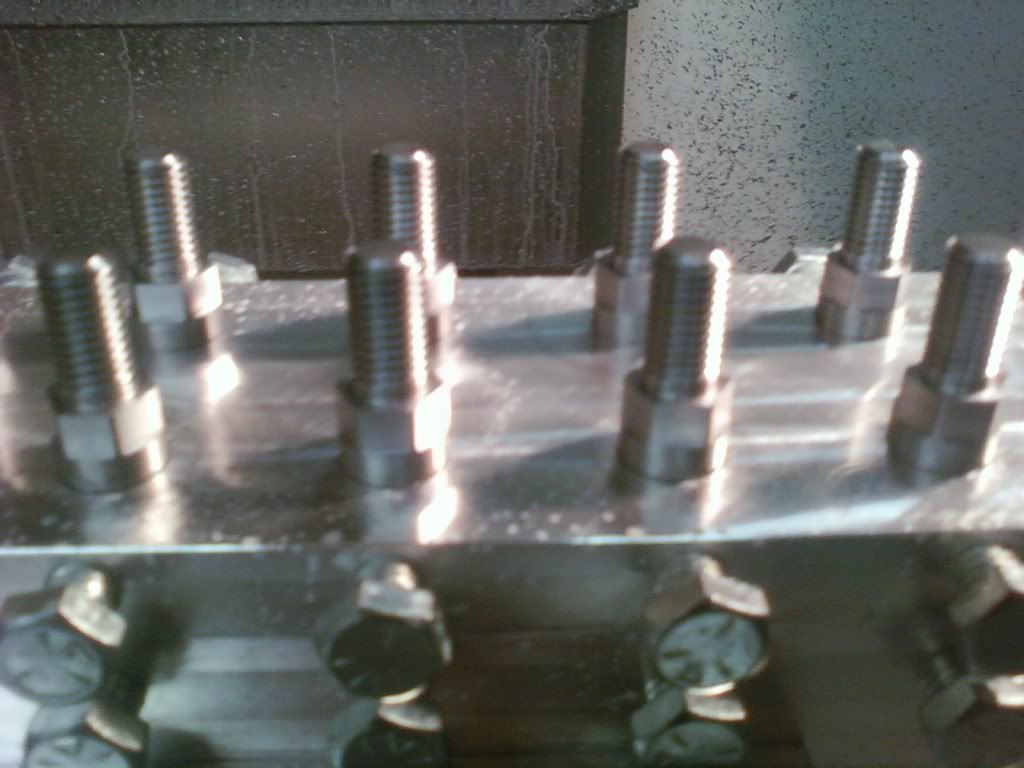
Hi Guys-Thought I would post a couple of completed jobs that I had asked questions about recently. Both used 28 position fixtures, the shorter steel parts have a machined OD so simple pockets worked well but the longer aluminum part was raw material that varied up to .008" so had to use a different style of fixture to hold them. The steel parts was a ridged setup and ran with out a problem. However the aluminum parts due to there length of 3" wasn't as ridged and did have a little chatter and required a finish up pass on the OD prior to threading.
I had hoped that I could get around 2 minutes per part which would be faster then by doing them one at a time in a CNC lathe. Cycle time for both came in right at 16 minutes each for each set up which was a lot faster than I expected.

-
03-11-2010, 02:37 AM #10
Registered
- Join Date
- Jul 2007
- Posts
- 378
NICE :rainfro:
Looks like you had your hands busy for a while.

 Reply With Quote
Similar Threads
-
Thread Mill Program
By october in forum G-Code ProgramingReplies: 8Last Post: 07-20-2016, 02:36 AM -
NEED THREAD MILL PROGRAM FOR C-AXIS
By BAD DOG in forum Daewoo/DoosanReplies: 10Last Post: 03-05-2015, 04:59 AM -
need sample program
By vintageracer in forum MilltronicsReplies: 3Last Post: 11-15-2008, 10:58 PM -
Need help with simple thread mill program
By Captain Midnigh in forum MilltronicsReplies: 14Last Post: 07-24-2008, 11:57 PM -
2-1/2 - 8 NPT Thread Mill Program
By wesleybridgepor in forum MetalWork DiscussionReplies: 2Last Post: 11-30-2006, 11:56 AM
