


Ok, so When I build a program in mastercam, when I go to post, the begining of the program looks like this:
G20
(TOOL - 1 OFFSET - 1)
(OD ROUGH RIGHT - 80 DEG. INSERT - CNMG-432)
G0 T0101
G18
G97 S431 M03
G0 G54 X1.7742 Z2.5769
G50 S3600
G96 S200
G99 G1 Z2.4769 F.01
So it wants a G54 position.
But my Miyano 6bc with a 6T controll, does not have option for a G54 posistion. How I understand it is that it was an option with fanuc. Some guys say that you need to use a G50 command. So would I just home the machine, then replace the G54 with the G50 in that mastercam post? This is the last step I need before I can make race car partsSo any help is greatly appreciated.
Results 1 to 13 of 13
-
02-17-2009, 07:04 PM #1
 Registered
- Join Date
- Jan 2009
- Posts
- 245
G54, G50 confusion on 6t controll
-
02-17-2009, 07:31 PM #2
Gold Member
- Join Date
- Jun 2008
- Posts
- 1511
PM sent.
Stevo
-
02-17-2009, 07:43 PM #3
Registered
- Join Date
- Oct 2007
- Posts
- 32
The G50 in that example just limits your spindle RPM it has nothing to do with any positions. The G54 is an option in a Fanuc control but not necessary to run as long as you teach you tools to the face of your material and/or use a WORK SHIFT. You should be able to just delete the G54 from your program if your machine does to have the Work Coordinate option turned on and leave the G50 (Max spindle speed setting).
-
02-17-2009, 10:41 PM #4
Registered
- Join Date
- Jan 2009
- Posts
- 245
So your saying in that sample program I just put there, I should be able to delete just the G54 itself and leave everything else the same? So as long as I home the machine then start that program without that G54 in there it will run as normal as long as the tool offsets are correct?
-
02-18-2009, 12:41 AM #5
Registered
- Join Date
- Sep 2005
- Posts
- 767
G50 is used to BOTH lmit the spindle speed in CSS and also to pre-set the position registers. If you specify :
G50 X1.2345 Z2.3456
The X absolute position display changes to 1.2345 and the Z position display changes to 2.3456. All X and Y motions are then relative to those points. Before the G54-G59 offsets were available, most 6T programmers would move a tool to a known position relative to the part, then give it the G50 X----- Z----- command, then select a tool offset and begin cutting with that tool. After moving back to a known tool change position, they would cancel that offset, change to the next tool, give it another G50 command with different X and Z numbers (to compensate for the tool length) then activate the new tool offset and begin cutting again. Using a G50 statement for each tool permitted tool offset values to remain very small, usually to only compensate for wear. When setting up a job, the procedure would be to zero out all the offset registers, touch off each tool, set the "relative" position display to X0 Z0, then move back to a safe tool change point and lift the G50 numbers from the relative display.
If you command a G50 S1000, then start the spindle in constant surface speed, the spindle speed will not go higher than 1000 rpm, even if the tool approaches the spindle centerline.
You can give all three together if you wish: G50 X1.2345 Z2.3456 S1000
Other programmers liked to take the LONGEST tool, touch off, back away, then use only one G50 command for the entire program. Then, the tool offset values for that longest tool are near zero, but all the other tools will probably have large tool offset values. This can be a problem because a T-command will activate or cancel the offset, causing a larger motion than the operator might expect from looking at the program.
Either method works. I liked to use a G50 for each tool.
-
02-18-2009, 05:51 AM #6
Registered
- Join Date
- Jan 2009
- Posts
- 245
First of all, thank you so much for your very usefull reply. Ok, I am a comoplete Lathe newb but very fluent in mill and manual lathe and mills.
Ok, lets say I have two tools. ONe is a facer and a turner, and the other is a part off tool. If I set my program to where its origin is the face of the chuck jaws. So where would I touch off my tools? ON the od of the part? I guess I am just confused on how to set the G50 command and the tool offsets. I looked in the offsets and the tool offsets are REALLY small, sorta like you were saying they would be, from the previous owner of the lathe. Any help is appreciated! THanks for any help.
When you draw a part on mastercam, you set the centerline on the centerline of the part, so I would figure you would set your G50 command to where the center of the part is the very tip of EACH tool for the x pos. And the Z position would always be on the face of the chuck, as long as that is how the program was written.
ALso another side note, When you send a new program to the CNC, if you dont give it another program number it errors out with a 073 error, which means that, that program number has already been used. So when you build a new program with a new program number, does it automaticly delete the previous program, or since it has a new number it is stoard somewhere?
-
02-18-2009, 10:50 AM #7
Registered
- Join Date
- Feb 2009
- Posts
- 3
Hi there. If you don't have the g54 option there should be a work shift page/button on the control that you can use to set the X and Z coordinates. The X coord should already be set to the center of the chuck and there for should not be touched. The z coord should be set according to your datum in the program. ie. Off the face of the chuck or off the front face of the job. Then as stated you can simply delete the g54 from the program and it should work. Also in your program you have a g50 setting your spindle speed to 3600 max. Remember to make sure you slow everything down when you first run every program (Rapid,feedrate) and put the optional stop and single block on aswell and put the position screen on it should have a distance to go coordinate so you can see where you are. ie if it says you have 200mm to go and your 10mm from the job then there is something wrong.
Also all programs are stored in the program library untill YOU delete them. So make sure your programs are stored on computer so you can delete them off the control otherwise you will run out of space.
Hope this helps
-
02-18-2009, 07:06 PM #8
Registered
- Join Date
- Jan 2009
- Posts
- 245
Here is an upload of photos of the machine, and I also included the page that is on the offset button.


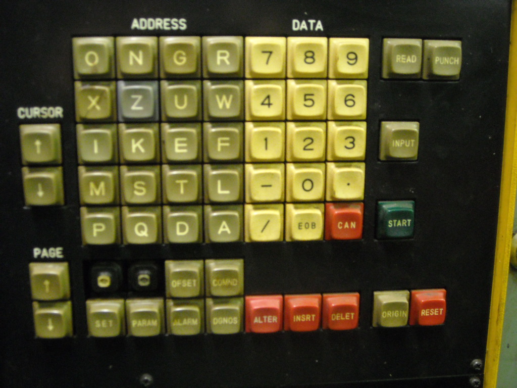
So there is NO 1, X, Z, R, T.
So how would these numbers be associated with the G50 Pos?
-
02-19-2009, 12:15 AM #9
Registered
- Join Date
- Jan 2009
- Posts
- 245
Ok, I have been at this all day. I am having so many problems.
1. When I bring the machine about 3-4 inches away from the home position after starting the machine. I go G28 u0 w0. It will error out about half the time with a X or Z OT, I have checked the limit switches (micro switches) and they all seem good, unless they are out of adjustment.
2. When I write a program like this:
O0000
G20
G0 T0101
G18
G97 S3000 M03
G0 X-.016 Z2.3818 M8
G50 S3000
G96 S200
G99 G1 Z2.2818 F.01
X.9691 Z1.7324
G18 G3 X.9842 Z1.7168 R.0312
G2 X1.9056 Z1.0674 R.9166
G3 X1.9378 Z1.04 R.0313
G1 X1.9379 Z0.
X2.0793 Z.0707
M9
G28 U0. V0. W0. M05
T0100
M30
It will go to the tool, but then will error out saying overtravel. I guess I am still unsure on which line the G50 needs to be used. So if you use a G50 command and have your X, Z and R values at Zero, your tool will tip will use that exact G50 position for its origin? So if you draw the part to where the origin is at the face of the chuck and on the centerline of the part, and you zero the machine, bring T1 down to the face of the chuck, and write that number down. Then chuck a 2" bar in the chuck, touch off on that bar with the x axis, then add one to that number and that will give the x position? Then if you have your values at zero for the offsets for t0101, your tool will be offset correctly?
So would the program look like this, if my x and z cordinate were 5.0 and 5.0 for a tool touch off?
O0000
G20
G0 T0101
G18
G97 S3000 M03
G50 x5.0 z5.0
G0 X-.016 Z2.3818 M8
G50 S3000
G96 S200
G99 G1 Z2.2818 F.01
X.9691 Z1.7324
G18 G3 X.9842 Z1.7168 R.0312
G2 X1.9056 Z1.0674 R.9166
G3 X1.9378 Z1.04 R.0313
G1 X1.9379 Z0.
X2.0793 Z.0707
M9
G28 U0. V0. W0. M05
T0100
M30
Am I on the write track or WAY off?
-
02-19-2009, 10:12 AM #10
Registered
- Join Date
- Feb 2009
- Posts
- 3
Hi there. I think your machine calls the tool and then over travels because it then tries to move Z2.3818 incrementally so it's trying to go backwards instead of towards the job. Try this to stop over travel problem.
O0000
G20 G18
G91 G28 U0. W0.T0000(G91 to move home in incremental)
G50 S3000
G0 T0101
G90 G96 S200 M3(G90 so it moves in absolute)
G50 G0 X-.016 Z2.3818 M8
G99 G1 Z2.2818 F.01
X.9691 Z1.7324
G3 X.9842 Z1.7168 R.0312
G2 X1.9056 Z1.0674 R.9166
G3 X1.9378 Z1.04 R.0313
G1 X1.9379 Z0.
X2.0793 Z.0707
M9
G91 G28 U0. W0. T0000 M05 (G91 to move home in incremental)
M30
Once again make sure you slow everything down before running!
Now its been a while since i ran a lathe with G50 work co ordinate. The lathe i run at the moment has a fanuc ot control and has a work shift page that's not g54 to set the job z/x o.
When you touch the tool tip on the chuck how do you enter the z offset into the offset page. ie. do you press (MZ0. and then press enter?) I have a fanuc manual at work ill dust it off and try to brush up on the G50 work co ord programming. Then run your program through the lathe and see what i come up with.
-
02-19-2009, 05:19 PM #11
Registered
- Join Date
- Jan 2009
- Posts
- 245
Ok, couple of things.
My machine does not recognize a G91 command. It alarms with error #10
Second I keep getting this error while either trying to zero the machine or just move it in the correct direction:
#213 or #212
By definition these erros mean it was moving in the plus or minus direction and it entered into the forbidden area of the stored stroke limit 1.
What is the stored stroke limit 1?
-
02-20-2009, 05:09 AM #12
Registered
- Join Date
- Feb 2009
- Posts
- 3
A stored stroke limit is a restricted area that has been set in the parameters. The tool should not enter these areas otherwise the system will show an alarm and all movements will stop. On the mdi screen see if your machine will respond to a G23 comand that should cancel the stored stroke check function. Then see if it will run.
-
04-05-2009, 09:15 PM #13
Registered
- Join Date
- Sep 2007
- Posts
- 66
try pushing te offset button more than once than ,on my machine i come in a x and z offset than i let the longest tool hit the z0. point and press mz0. [input]
then the valeu changes the same for x.
it works the same on the tool offset ,let the next tool hit the same position then go to tooloffset and press mz0.[input] a valeu apears (the differents in lengt between the tools)
i believe that every machine can get one workpice zeroset other than the machine reference point. because if youre machine was 2000mm long that would be redicules!!!!!!
MY MESURMENTS ARE IN MILLIMETERS!!!!!!!!!!!! TYPED IN RED!!!!!!
if you make you're program like this copy from an other repley you get overtravel because the machine wants to compensate. example T1+L50.mm so it wants to go z+50.but you already sent it to it's max z point by bringing it to G28G91 X0. Z0.
if you want to decompensate ,you put that in a sentense before you go back to the reference point take notice that that valeu is more than youre tool offset
or else it moves forward!!!!!!
O0000
G20 G18
/G91 G28 U0. W0.T0000(G91 to move home in incremental)
G50 S3000
G0 T0101 X100. Z5. (PUT A SAFE X AN Z HERE AND THE OVERTRAVEL IS GONE)
G90 G96 S200 M3(G90 so it moves in absolute)
G50 G0 X-.016 Z2.3818 M8 (I WOULDT NO RECOMENT THIS ,THIS SCREEMS FOR ERROR)
G99 G1 Z2.2818 F.01
X.9691 Z1.7324
G3 X.9842 Z1.7168 R.0312
G2 X1.9056 Z1.0674 R.9166
G3 X1.9378 Z1.04 R.0313
G1 X1.9379 Z0.
X2.0793 Z.0707
G0 G90 X250. Z250. T0000 (A SAFE TOOL CHANGE POINT)
M9
G91 G28 X0. Z0. M05 (G91 to move home in incremental)
M30
THE G50 CODE IS GOOD FOR LIMMITING RPM'S BUT NOT FOR WORK ZERO POINTS .FORE THAT DOING EVERY THING INCREMENTAL ,IS TO CONFUSING .
YOURE READING IN THE ABSOLUTE POSITION SCREEN WOULD MAKE NO SENCE .
I HOPE YOU CAN JUSE THIS ,AND WEN IT NOT CLEAR YET GIVE A MESAGE
GREETINGS BERTUS.NL THE NETHERLANDS

 Reply With Quote
Similar Threads
-
Where to set G54 position for 6T controll.
By blakemachine in forum FanucReplies: 4Last Post: 02-09-2009, 02:59 PM -
drill post to c6 controll
By idealtool in forum MilltronicsReplies: 8Last Post: 11-06-2008, 10:08 PM -
C code for CNC machine controll
By stan2323 in forum CNC (Mill / Lathe) Control Software (NC)Replies: 3Last Post: 10-27-2008, 03:12 AM -
Post for Mitsubishi Controll
By Maguillacutty in forum SurfcamReplies: 4Last Post: 08-02-2008, 03:18 PM -
GN10T-F symbolic controll
By Craig F in forum FanucReplies: 2Last Post: 05-25-2006, 06:32 PM
