


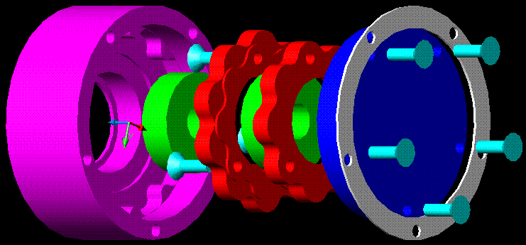
I want to build a rotary table that can handle continuous milling!
Do you think my drawing would work?
The upper gear belt pulley can rotate freely on the axle, and is connected to the axle via the spring, and is preloaded.
Thread: Backlash free rotary table
Results 1 to 20 of 1027
Hybrid View
-
01-25-2009, 06:54 PM #1
 Registered
- Join Date
- Jan 2009
- Posts
- 81
Backlash free rotary table
-
01-25-2009, 07:12 PM #2
Registered
- Join Date
- Mar 2006
- Posts
- 2712
As an alternative, "google" Howimat. This concept is ball driven like a ballscrew in the round.
Dick ZDZASTR
-
01-25-2009, 07:15 PM #3
Registered
- Join Date
- Jan 2009
- Posts
- 81
I will check it out! I have also been thinking of using 2 servos and do the preload eletronically with a µC
-
06-02-2014, 09:44 AM #4
Registered
- Join Date
- Oct 2011
- Posts
- 27
Re: Backlash free rotary table
this Patent US5286236 - Ball-type speed reducer - Google Patents
can get to zero backlash if tight enough
I saw no comments about the hypocycloid reducer link I posted. It seems clearly DIY level since somebody made one...
would be worth looking into.
-
01-27-2009, 09:26 PM #5
Registered
- Join Date
- Jan 2008
- Posts
- 30
I poked around the DetlevHofmann site, and while they mention the Howimat drives, there is almost no info. They do mention a patent but I couldn't find it. I was wondering if anyone has seen the patent, or knows where it is? Originally Posted by RICHARD ZASTROW

Regards,
Raymond
-
01-27-2009, 09:34 PM #6
Registered
- Join Date
- Jan 2009
- Posts
- 81
Did just draw a 105:1 gearbox!
The housing is 100mm diameter and 45 mm long.
-
01-25-2009, 08:09 PM #7
Registered
- Join Date
- Aug 2008
- Posts
- 573
Looks like it would work to me, although mixing gears, lubricant and timing belts might be a problem.
How about placing the two worm gears at an angle to each other, driving one directly and the other via a bevel gear? (if you see what I mean)
Or...
What about a buying or copying Commercial anti backlash worm drive ?Bill
-
01-25-2009, 08:16 PM #8
Registered
- Join Date
- Jan 2009
- Posts
- 81
Hmm, thats an interesting idea! I'll make a drawing!

-
01-25-2009, 09:30 PM #9
Registered
- Join Date
- Jan 2009
- Posts
- 81
Faliure
I made a drawing and realized that the worms would need to rotate in the same direction in this configuration :P
The dual servo version seems more and more appealing!
-
01-25-2009, 10:18 PM #10
Gold Member
- Join Date
- May 2005
- Posts
- 2502
There are a lot of commercially available low backlash drives on eBay. Search for "harmonic drive" or "bayside drive". One of those sure will least trouble and expense.
Another possibility is to preload the heck out of your rotab drive with another gear and some bellvues. Not sure how much torque you plan to put on it though.
People also run 2 of the main circular gears spring loaded to spread the teeth just enough to get rid of the backlash. In this case, you'd make the spread adjustable with a threaded screw.
These last two solutions seem prone to binding and wear.
I would be tempted to also consider a big timing belt drive. properly set up, you'll get minimal backlash. People are even using these for linear motion with good success.
For really high torque situations, you might still find a brake is useful. Slew the 4th axis to the desired position, send an M-code to lock the brake, cut, and unlock. Small disk brakes from everything from mini-bikes to lawn tractors are readily available and work with an air over hydraulic and solenoid valve.
Cheers,
BW
-
09-08-2009, 09:29 PM #11
Neuer Benutzer
- Join Date
- Apr 2007
- Posts
- 29
You could use a right and left threaded worn screw but in your desing, backalsh is transfered to the bevel gears!! Originally Posted by Zoidberg
Keep going on design, i am also interested in a rotary axe.
thanks
petecul
-
01-25-2009, 10:11 PM #12
Registered
- Join Date
- Aug 2008
- Posts
- 573
Just swap the main-shaft bevel gear to the front of the perpendicular one.
Bill
-
01-25-2009, 10:19 PM #13
Registered
- Join Date
- Jan 2009
- Posts
- 81
Aaah yes...
:withstupi
-
01-25-2009, 10:38 PM #14
Registered
- Join Date
- Jan 2009
- Posts
- 81
I want it to be able to use it for continuous milling, like gear hobbing and milling springs, not just indexing!
I think it's best to have the worms axially stiff because they can't be backdriven. So if you just can keep both worms in contact with the gear teeth with a little rotational preload it should be backlash free and much stiffer than the version with axial preload of the worms or split wormgear!
Harmonic drive seems nice! But i like to design and build stuff more than paying for complete solutions
I was thinking of a gear belt drive at first.. but it's a little impractical when you want 1:100 ratio or so..
-
01-25-2009, 11:11 PM #15
Registered
- Join Date
- Feb 2007
- Posts
- 1084
Originally Posted by Zoidberg
Machine your own harmonic drive
Would probably be the best solution for your application, you can get 100:1 no problem, and I'm pretty sure most of the new 4th axis equiptment are using harmonic drives? It's how I ran accross them.
Decent load handling, probably indefinate gearing available, no backlash due to design, compact and readily available.
But if your determined to make it all yourself, I like the duel servo idea. But are you going to make the servo's?:stickpoke
Just joking, I get it,
MC
-
01-26-2009, 12:25 AM #16
Registered
- Join Date
- Jan 2007
- Posts
- 210
Just a couple of basic engineering things to think about.
Solid worm gears need some clearance to operate or they lock. Worm gears are not very efficient which is why they don't backdrive easily.
Let's say you adjust your drive worms for .0001 clearance. Have you thought about runout on the main gear? This is why Hass hobs their gears after they are mounted. Ever priced a class 9 worm gear set? I pay over $4500 for mine and they are only 6 inch in dia.
Spring loaded worm gears use very light springs to allow the halves to move when operating. Because of this it's very easy to overcome the springs and they have very limited top speeds or they wear like crazy from the sliding friction between the worm and wheel.
The wheel gear is fairly large and grows and shrinks with temp changes. Set one up in a 68 degree room with almost no clearance and it will be locked solid when the wheel temp goes up to 80 degrees. Worm gears generate a fair amount of heat when running because the sliding friction is so high.
Harmonic drives can be purchased in zero mechanical backlash configurations but the main drive flexspline is made of spring steel and will deflect under pressure (although not as much flex as a split worm gear). Grab the end of a robot arm and move it back and forth. Older robots are almost all harmonic drives.
Dual worms driven by servos are a nice idea but how do you get around the problem that the gear teeth are not going to be exactly spaced. You have to consider manufacturing tolerances into any design work. No gearset is perfect.
There are also high resolution direct drive rotary motors. Basically linear motors wrapped in a circle. These are used in the rotary axis of very high end machine tools and high priced robots. Very expensive and they still have at least +/- 5 counts of "backlash".
IMO a harmonic drive from e-bay makes a good option (they are very expensive purchased new). Be aware that they are not all "zero backlash" units and mounting accuracy of the components is critical. They also take up more room than a worm drive.
DDR motors are great but they require very high resolution feedback devices and sophisticated controllers.
Worm gears work but you just have to live with some backlash in a fixed design or give up top speed and realize life will be shorten in a spring loaded design.
The life of any machine designer is full of tradeoffs.
BobYou can always spot the pioneers -- They're the ones with the arrows in their backs.
-
04-21-2009, 04:44 AM #17
Registered
- Join Date
- Mar 2007
- Posts
- 41
Building a 90:1, dual stage cycloidal reducer
Inspired by this thread and the .pdf found by aystarik, I built a dual stage 90:1 cycloidal reducer. The main issue in creating the reducer is the generation of the cam profile as it is a fairly complex function. To solve this problem I wrote a Python script to automatically generate a .dxf file with the specified parameters.
Autocad drawing of the reducer:
A shot of the inside of the reducer showing the 9 lobe cam on top, the 10 lobe cam on bottom meshing with the 11 outer pins in the housing:
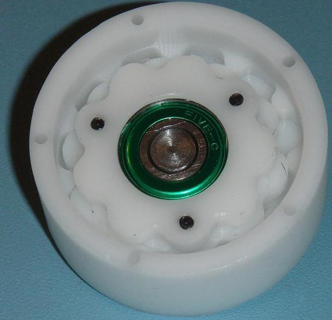
The reducer was machined from 2" diameter Delrin rod I had lying around.
Video of the reducer in operation. The drill is running at around 2000rpm and I can only hear the noise from the drill.
[ame="http://www.youtube.com/watch?v=Ye8NtIZkixI"]YouTube - Hypocycloid reducer[/ame]
If you would like the script I used to generate the cams and some more pictures, see my page on the subject
I plan to make an new version with two bearings on the input shaft as the single bearing allows some play. I also need to measure the backlash.
-
06-10-2009, 06:38 PM #18
Gold Member
- Join Date
- Feb 2009
- Posts
- 6028
Or just buy the mori or hardinge direct drive unit. Can run at a constant speed no problem, no gears, no backlash.
-
06-10-2009, 07:15 PM #19
Gold Member
- Join Date
- Dec 2004
- Posts
- 524
Has anyone considered making one of these?
http://urobotics.urology.jhu.edu/projects/BW/
They can be made with zero backlash and low friction.
KenKenneth Lerman
55 Main Street
Newtown, CT 06470
-
01-25-2009, 10:24 PM #20
Registered
- Join Date
- Feb 2007
- Posts
- 1084
Harmonic Drive is the way to go, if your willing to spend a little money.
http://www.powertransmission.com/iss...6/harmonic.htm

 Reply With Quote
Similar Threads
-
Backlash free R&P
By Al_The_Man in forum Linear and Rotary MotionReplies: 2Last Post: 03-07-2014, 06:28 PM -
Adding a rotary encoder to a large Rotary Table
By small.planes in forum Mechanical Calculations/Engineering DesignReplies: 14Last Post: 04-27-2012, 07:27 PM -
Phase II 4" rotary table backlash.
By TXFred in forum Benchtop MachinesReplies: 14Last Post: 02-12-2011, 01:27 AM -
Rotary Table Backlash
By fc911c in forum Uncategorised MetalWorking MachinesReplies: 4Last Post: 04-18-2010, 10:11 AM -
Typical Backlash on a new Yuasa 8" Rotary Table
By Roy Norris in forum MetalWork DiscussionReplies: 5Last Post: 08-10-2005, 10:33 AM
