


OK I ordered the 48V Power supply can someone point me to where to get steppers 260-300oz for the three axis I need them for specifically with the thru shaft design to add adjustment knobs for ajsting the axis whe the steppers are off
Results 21 to 38 of 38
-
09-19-2008, 05:58 AM #21
 Registered
- Join Date
- Jul 2008
- Posts
- 85
-
09-19-2008, 10:55 PM #22
Registered
- Join Date
- Jul 2008
- Posts
- 22
I have Keling KL23H276-30-8B's which can be found at
These were recommended by several people and Keling is a very reputable supplierHTML Code:http://www.kelinginc.net/NEMA23Motor.html
-
09-23-2008, 03:24 AM #23
Registered
- Join Date
- Jul 2008
- Posts
- 85
Well got most of what I need or atleast half
Setup Taig Mill Today have to find machinist square tommorrow to square bed to spindel. I installed Keling 282oz Steppers Received 48V 12A Switching Power Supply and My Gecko 540 Controller
List to go
Refurb one of my spare PC's
Sherline Rotary Table with Servo and Tail Stock
48" Cue Fixture
and Software to run this PUP

-
09-23-2008, 03:38 AM #24
Gold Member


- Join Date
- Feb 2007
- Posts
- 4553

Make sure you get the Sherline rotary with a stepper motor, not a servo.
Jeff...
-
09-23-2008, 03:53 AM #25
Registered
- Join Date
- Jul 2008
- Posts
- 85
Thank You Sir Originally Posted by jalessi

 Will Do indeed. Now I am debatin if I am going to mount directly to the ugly 35 yr old bench its on it solid wood with a formica top or if I should use some birch plywood
-
09-23-2008, 08:35 PM #26
Registered
- Join Date
- Nov 2007
- Posts
- 980
Looking good, but if the birch plywood won't be covered with anything, I'd stick with the laminate top for easy cleaning -
DaveDave->..
-
09-24-2008, 01:52 PM #27
Registered
- Join Date
- Jul 2006
- Posts
- 887
Here are some helpfull tips for setting up the g540.
When setting up the pc. make sure the printer port is in EPP mode in BIOS (CMOS)
If you are not setting up a external E stop switch, then you will probably need to take a jumper wire from pin 10 (on the side of the g540 and jumper this to the ground pin on the g540. If you experiance troubles when milling (I could jog and everything looked good but when I cut a g-code it was way off) you may have to setup mach 3 in Sherline 1/2 pulsing mode.
make sure you setup the charge pump pin in mach3 (pin 16)
Good luck and a am awaiting your results because I spent almost a week trying to figure this out!
-
09-24-2008, 10:58 PM #28
Registered
- Join Date
- Jul 2008
- Posts
- 22
Please post rapid speeds as soon as you get setup... and remember, you can tell them to fast as you want and they won't know that they cant, the only way (that i know of) to know their actual max is the method i described in my first post. I would say start at 20 ipm (or about 500mm/m) and work your way up at either 5ipm of 100mm/m intervals...
A few other things:
-You can use machine coordinates and soft limits to eliminate the chance of running into your fixtures,just watch the mach 3 tutorial video on coordinates
http://www.machsupport.com/videos/
-In a lot of situations it is probably going to much simpler to treat your rotary axis as if it were linear one. You would just say I want this to be 1 inch tall and go half way around the shaft. Your drawing would have the same length dimension (up/down the shaft) and your width would be (pi)(shaft dia.)(.50). You could even make a wrap around design so long as the edges of your drawing (not top/bottom, the other two) match up. Now if you had a tall design you would have to compensate for the narrowing diameter of the shaft. Perhaps you could do something with the formula option in Mach3? Been meaning to look into that feature..... The other option would be generating g-code for a rotary axis, not sure how fun that is...
Of course I assuming your into butt (the lower half of the cue for anyone who doesn't know) designs. Linear tapers should be easy and curvilinear ones (if any of the shaft tapers are??) aren't very complicated, you can just use a set of 3 points to define the curve on a freeware CAD program, save as .dfx and import into Mach 3. Just let me know and I'd be happy to elaborate on any of these processes.
-
09-25-2008, 07:30 AM #29
Registered
- Join Date
- Jul 2008
- Posts
- 85
Where can I find a good push button kill switch for this pup
-
09-25-2008, 07:44 AM #30
Registered
- Join Date
- Jun 2008
- Posts
- 467
http://tinyurl.com/4bpewj
Kind of looks like our products.
JoeyB
-
09-26-2008, 01:37 AM #31
Registered
- Join Date
- Jul 2008
- Posts
- 85
One last question for now. Any one direct a good place to get a lockable wall mount project box to place the controller power supply and emergency stop button in perfer aluminum or steel as long as its large egnough to house everything
-
09-26-2008, 04:04 AM #32
Gold Member
- Join Date
- Dec 2004
- Posts
- 1865
I several nice used cabinets.
PM me if you are interested. I will be putting them up for sale next month to the general public but if I can help now I will.
Mike
-
09-26-2008, 04:49 AM #33
Registered
- Join Date
- Jul 2008
- Posts
- 85
I am very interested please post prices and pics
-
09-27-2008, 08:33 AM #34
Gold Member
- Join Date
- Dec 2004
- Posts
- 1865
 Pictures tomorrow. Originally Posted by gunlocators
I got attacked by some unscheduled overtime (nuts)and I don't have the pictures with me.
Mike
-
10-01-2008, 12:30 PM #35
Gold Member
- Join Date
- Dec 2004
- Posts
- 1865
Control box pictures
Dear Gunlocators.
I was attacked by even more unscheduled overtime so I appoligize for the delay in posting pics.(nuts)
It is 20"tall by 16" wide and is 10" deep plus the door which is another 1" or so.
I would like $50 plus shipping for this one. I have a couple more that are in better condition but they are buried under my pile of stuff. I am finishing up my retro fit and will be putting more stuff on ebay in the next month or so.
The good thing about the overtime is I can buy more stuff for the shop:banana:
Mike
-
10-01-2008, 02:08 PM #36
Gold Member
- Join Date
- Sep 2006
- Posts
- 1738
Here is how my enclosure box is turning out for my Gecko 540, Keling PS, Keling E-Stop and then other goodies.
This is for my Taig and so far from testing, it flys! My resistors come in today, but don't know if I will have time as I need to study for exams.


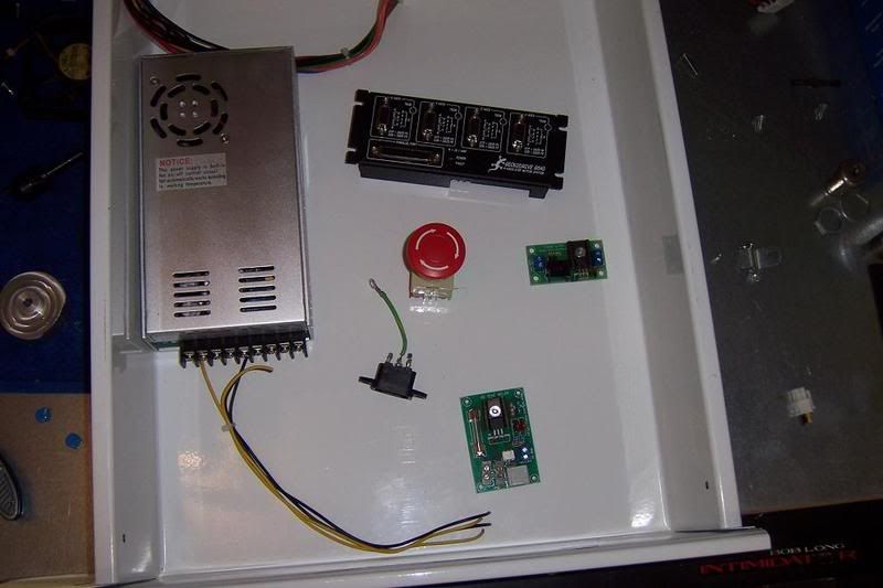
I got plenty of room The first things to do is cut out the panel slots, which I will do in a few days.
-Jason
-
10-03-2008, 06:07 AM #37
Registered
- Join Date
- Jul 2008
- Posts
- 85
Well got a little further in the project decided to use a old breaker box with some vent holes for ps and controller. Also have a pc with mach 3 and optimized now i just need to learn to properly wire the steppers to the right pin config for the cables and to properly config the power supply ect to the gecko 540. Anyone wanna lend a hand
LOL
Anyhow here my most recent pic

-
10-03-2008, 12:50 PM #38
Registered
- Join Date
- Jul 2006
- Posts
- 887
Dont be afraid of it, it is very straight forward. What I did was wired up my cables to the ends all the same. then I wrote on a piece of paper, what color was a a# b and b# seeing as my cables did not match the colors of wires on my steppers.
Then I looked up my steppers on the internet and found what colors were what. Wrote it down on paper that red went to orange black to yellow ect. I used wire nuts to make the connections. To make sure it all went well, then went back and soldered and heat shrinked them one at a time

 Reply With Quote
Similar Threads
-
HELP ME- taig and mach 3 setup
By hollyfeneht in forum Taig Mills / LathesReplies: 21Last Post: 02-05-2007, 07:57 PM -
Taig 4th axis setup
By gabi68 in forum Mach MillReplies: 4Last Post: 01-11-2007, 06:02 AM -
G-rex users lets hear how its going
By Drew in forum Machines running Mach SoftwareReplies: 8Last Post: 01-10-2007, 11:08 PM -
New Taig in mind help on setup please
By mdoan in forum Uncategorised MetalWorking MachinesReplies: 0Last Post: 10-25-2004, 08:16 AM -
Taig CNC ready setup help??
By efreak in forum Taig Mills / LathesReplies: 2Last Post: 08-25-2004, 01:30 AM
