


sorta like how i did it here, or do i only need to do strait corners, and the cam will just figure it out?
thx
Results 1 to 11 of 11
-
09-09-2004, 10:34 PM #1
 Registered
- Join Date
- Sep 2004
- Posts
- 30
when im doing cad, do i need to have round corners as in real model?
-
09-09-2004, 11:26 PM #2
Registered
- Join Date
- Apr 2003
- Posts
- 1873
In this case you are going to get round corners even if in the cad drawing the corners are square, has something to do with the round end mills I think

-
09-10-2004, 01:54 AM #3
Registered
- Join Date
- Sep 2004
- Posts
- 30
so i don't need to worry about it...cool, thx, also when im doing the CAD figure, i just have to do a basic wire frame model rite?
-
09-10-2004, 02:12 AM #4
Community Moderator
- Join Date
- Mar 2003
- Posts
- 35538
What do you mean by a basic wireframe? Usually it needs to be either a solid model or a surface model. It depends on what the CAM package you'll be using needs.
Gerry
UCCNC 2017 Screenset
http://www.thecncwoodworker.com/2017.html
Mach3 2010 Screenset
http://www.thecncwoodworker.com/2010.html
JointCAM - CNC Dovetails & Box Joints
http://www.g-forcecnc.com/jointcam.html
(Note: The opinions expressed in this post are my own and are not necessarily those of CNCzone and its management)
-
09-10-2004, 02:25 AM #5
Registered
- Join Date
- Apr 2003
- Posts
- 1873
I had posted at 6:26 and I close here at 6:30 so I got in a hurry, let me add,
You will not need to inside fillet with in the cad program, unless the corner radius you want to end up with is not the same size as your cutter radius.
Say your want to end up with a corner radius of .250 and you are going to use a .5 cutter then you are good to go without filleting the corners in your drawing, but if you wanted .250 radiused corners and are using a .250 end mill (.125 radius) then it would be necessary to fillet the corners in the drawing prior to creating code.
Make any sense?
In this case a 2D drawing would be all that you really needed.
Ger21 is correct in some case like on the little square pillars and using a small end mill the CAM may try to machine down the center of the square, in which case these may need surfaced so it goes around them and not down them.
BTW, did you decide on copper or aluminum?
Attached is a example of a 2D only drawing with sharp corners and the tool path simulation showing the outcome. Not like your drawing but close enough that you should see what is going on.
-
09-10-2004, 04:15 AM #6
Registered
- Join Date
- Sep 2004
- Posts
- 30
um, im using bobcad-cam rite now, im totally clueless how u can get a surface model, rite now im just drawing lines, making a 3d wire frame model of my block, here's a pic:
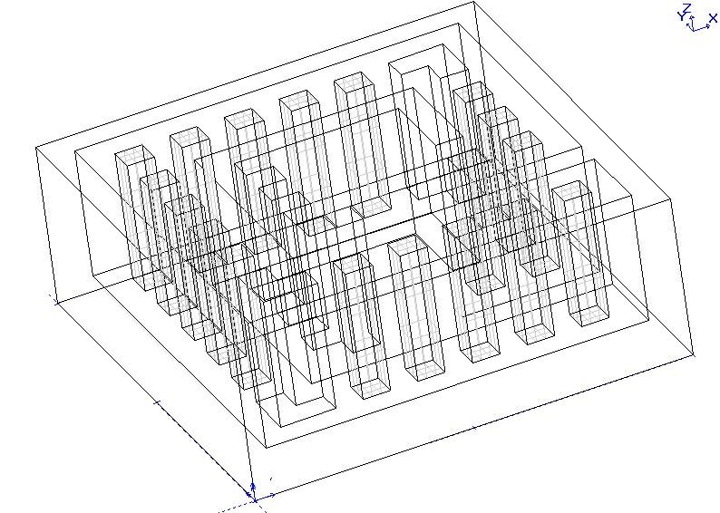
i hope im doing what im supposed to, or else i wasted 6 hours, lol
if im doing it rite, what am i supposed to do afterwords?
-
09-10-2004, 01:55 PM #7
Registered
- Join Date
- Apr 2003
- Posts
- 1873
Looks like you have a great start going and doing pretty good with it. I have not a clue where you would go from here because I do not anything about BobCad/Cam or the tool path strategies that are available, I am reasonably familiar with mine and have zero experience with any other. Wire frames are for me very difficult to view because of all the optical illusion's going on, so if this were my part using your CAD I would extract all and only those lines on Z-0 and blank all the rest leaving only the 2D flat top of part geometry.
How you would do that in your CAD or what is next in creating the G-Code I can't help you with.
In my example I used the pocket and pick by boundary tool path strategy. You control all the cutting parameters like the type of cutting tool and diameter, approach, depth of cut, speed, feed, step over and others depending on what is available with in your CAM software.
Just do what you have been doing with the CAD and little by little you will make progress.
-
09-10-2004, 06:36 PM #8
Registered
- Join Date
- Sep 2004
- Posts
- 30
yeah, gotcah, thx alot!
-
09-11-2004, 01:32 AM #9
Registered
- Join Date
- Sep 2004
- Posts
- 30
Ah, wait here?s a screenie:

but, as u can see, the block isn?t totally solid..only the rectangular cubes are what do I need to do to make it just one block? (for the columns, I used the already made solids that bobcad-cam offers)
-
09-11-2004, 03:30 PM #10
Community Moderator
- Join Date
- Mar 2003
- Posts
- 35538
You might want to ask in the BobCAD forum here, since your really asking BobCAD specific questions.
Gerry
UCCNC 2017 Screenset
http://www.thecncwoodworker.com/2017.html
Mach3 2010 Screenset
http://www.thecncwoodworker.com/2010.html
JointCAM - CNC Dovetails & Box Joints
http://www.g-forcecnc.com/jointcam.html
(Note: The opinions expressed in this post are my own and are not necessarily those of CNCzone and its management)
-
09-11-2004, 04:47 PM #11
Registered
- Join Date
- Sep 2004
- Posts
- 30
okey i did, thx

 Reply With Quote
Similar Threads
-
CAD Drafters Needed
By CAD Ground in forum Employment OpportunityReplies: 0Last Post: 03-11-2005, 06:05 PM
