


Hi
I just bought a Robodrill and am busy evaluating CAM software to use, I was hoping that the truemill paths would greatly increase the milling abilities on this little drill/tap machine however am having problems with finishing. I am used to programming G-Code on lathes as well but this is my first time on a CNC mill.
The process I use is:
Draw the model in Solid Edge, save.
Open with Surfcam, works fine.
Nc-> 3Axis-> Truemill, works wonders, very nice paths and quick.
Now finishing... hmmmm if using Z-Finish it doesn't work all that well, using 3D offset at .5mm it will clean the whole model if set at 1mm it won't cut all planes unless they fall within the 1mm increment, with it's first plunge it rapids into the left over material.
Also why is it that in the finish modes it doesn't do Arc's but instead a huge amount of fine straight cuts?
Can anyone suggest any good software for the Robodrill?
Thanks,
Jonathan.
Thread: Finishing
Results 1 to 17 of 17
-
02-26-2008, 12:48 PM #1
 Registered
- Join Date
- Aug 2006
- Posts
- 89
Finishing
-
02-27-2008, 02:47 AM #2
Registered
- Join Date
- Sep 2007
- Posts
- 3
In the operations manager select ArcFltr before you post, and it should generate arcs for you.
-
02-27-2008, 08:25 AM #3
Registered
- Join Date
- Aug 2006
- Posts
- 89
Okay thanks, haven't done any posting yet, just noticed this on the simulation.
-
02-27-2008, 12:32 PM #4
Registered
- Join Date
- Aug 2006
- Posts
- 89
So far I figured might as well fix it in the code...
FYI I get:
G0 Z10.
X-1.527 Y94.969
Z-14.5
G1 Z-17.
The Z-14.5 should be Z1.0 or taken out.
I suppose it isn't the end of the world, just cuious why it does it...
Next step, getting a post for 31i-A5, if anyone has one please Otherwise I'll write one next week when I get the manuals for the machine.
-
02-27-2008, 11:11 PM #5
Registered
- Join Date
- Aug 2006
- Posts
- 89
Okay looked at it again, and it is still messing up with finishing...
Oh well, will stick with edgecam then.
-
02-28-2008, 03:06 PM #6
Registered
- Join Date
- Apr 2003
- Posts
- 637
Jonathan,
Surfcam is certainly capable of giving excellent results but it will be difficult to help without some idea of the shape you’re cutting. Can you attach a copy of the model or surfaces? There are multiple ways of finishing and depending on the shape, some methods will give better results than others. Have your Surfcam dealer walk you through each method using your part files. I use it daily to cut mold cavities and get results so smooth that polishing has been reduced to just minutes compared to hours before CAM software. BTW, don’t worry about those small lines, if you set your surface tolerance to .0002 or less you won’t see them.
-
02-28-2008, 05:29 PM #7
Registered
- Join Date
- Aug 2006
- Posts
- 89
Hi
Thanks for taking the time to respond, it is actually a 2d/2.5d part.
I tried 2d Truemill but got no where.
We will go through it after the machine is installed next week, but I would like to be as ready as possible until then...
I am sure I am doing something wrong but I've tried all the finishing options without success. Now I have Truemill setup to leave 0 material for feedback then end up finishing the Z planes afterwards, I'll run it soon to see if it crashes or not..
PS: Is it normal for it to take some time to calculate the Truemill paths?
-
02-29-2008, 03:02 PM #8
Registered
- Join Date
- Apr 2003
- Posts
- 637
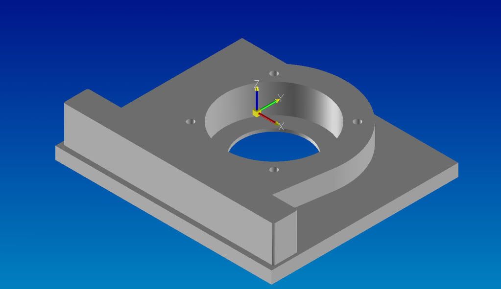
Truemill for finishing is not always a good idea. Use it to rough then finish with a combination of contour and pocket routines; should only take a few minutes to program. It shouldn't take more than a few seconds to generate the tool path with Truemill on a recently built system. Z finish would never be used on a part like this unless the walls are tapered but there are other ways to handle that. The program for the outside radius and inside diameters should not produce short, segmented lines unless the geometry became splines in the translating process. If that is the case just redraw the arcs/diameters in Surfcam. Originally Posted by jrobson

-
02-29-2008, 04:20 PM #9
Registered
- Join Date
- Aug 2006
- Posts
- 259
truemill can take some time if you give it a small tool engagement angle or other bad settings, but with that part up there, that would take no time to make a working program using truemill for roughing, contour 2d for finishing and a drill op. if you want to post the scprt file, I'll program it out for you so you can see what I would do. Also tell me what type of material it is..
-
03-02-2008, 11:11 AM #10
Registered
- Join Date
- Aug 2006
- Posts
- 89
Hi
Thanks for the tips, getting better, not yet 100%, but please let me know what you think. What format is best to use for importing? It seems that Surfplan reads the circular bits in solids from SE incorrectly(Lots of lines instead of circles), I am worried if I put a real 3D part in I won't be able to fix it with the provided 2D tools.
-
03-02-2008, 11:22 AM #11
Registered
- Join Date
- Aug 2006
- Posts
- 89
Material is mild steel.
-
03-02-2008, 05:49 PM #12
Registered
- Join Date
- Apr 2003
- Posts
- 637
I imported the file without any problems and don’t see any small lines in the wire-frame. From Solid edge to Surfcam the best would be Parasolid x_t files. Surfcam can read SE files (.par), but I found it better to just use x_t. When you import files, with most of the formats the geometry will be separated into two categories, wire-frame and surfaces, each put on separate layers. For your part you can turn off the surface layer (223 in this file) because you don’t need surfaces to machine this part, only the wire-frame is needed. Perhaps you were seeing the surfaces with it’s many short lines? I’ll let “tnik” program the part for you, should only take a few minutes for an experienced user.
-
03-02-2008, 08:25 PM #13
Registered
- Join Date
- Aug 2006
- Posts
- 89
Hi
It doesn't show up in the wireframe, but in the verification, I drew 2 circles in surfcam and that produced a G3 only, with the 3d truemill when it rough's the circle it generates a large amount of code, more straight lines than circles... Also note the 2 corners by the shoulder in verification it cuts them with a bunch of 5mm R circles instead of a single 10mm R, when I draw an arc using surfcam it cuts a proper single 10mm. I hope I am on the right track, excited to see the proper way though!
-
03-02-2008, 10:35 PM #14
Registered
- Join Date
- Apr 2003
- Posts
- 637
Sorry I thought you were talking about the geometry of the part after it’s imported into Surfcam (BTW what is Surfplan?). I’m not an expert with TrueMill but from what you’re describing it sounds about right. That is the way TrueMill works. Yes, it does make huge files but you can increase your feeds and depth of cut thereby vastly shortening the time to cut your part. All those arcs in the tool path are normal, putting less stress on the cutter. Sounds like you need to see some demo of the product...
Check this out:
[ame="http://www.youtube.com/watch?v=XfjOCQm52Ic&NR=1"]YouTube - SURFCAM Velocity TrueMill[/ame]
[ame="http://www.youtube.com/watch?v=rpPNzflBZ9U"]YouTube - SURFCAM Velocity TrueMill[/ame]
And from Surfware’s website:
http://www.surfware.com/default.asp?contentID=553
A little explanation of how it works:
http://www.screencast.com/users/Surf...2-b6090282fa17
-
03-02-2008, 11:20 PM #15
Registered
- Join Date
- Aug 2006
- Posts
- 89
Hi
Sorry spelling mistake. I know what you mean with the roughing, I understand the paths, however didn't know it does it with circles as well, thought only with corners...
I think it is to do with the way it renders and not the actual way the part will look, I'll cut something and give it a shot.
-
03-05-2008, 09:58 PM #16
Registered
- Join Date
- Aug 2006
- Posts
- 259
as moldcore said, it would only take a few min.. but I haven't had it, I apologize. I did look at your model, and the major problem I saw was there was alot of extra geometry.. eg. double / quadruple lines on top of each other.. I would check with whatever your using to import.
I looked at it monday so its not fresh in my mind.. I'll try to make some time in the next couple days to do it for you.. sorry for the delay..
-
03-06-2008, 10:59 AM #17
Registered
- Join Date
- Aug 2006
- Posts
- 89
Thanks, no worries about the delays, on that one I might have created some of those extra lines, from your guy's tips I've managed to work out a bit better how it works, I've now done 2d truemill paths on that part and it seems to work well, however would still very much appreciate if you could do it the way you would so I can compare.
Regards,
Jonathan.

 Reply With Quote
Similar Threads
-
3 Axis Finishing
By jamesr in forum SurfcamReplies: 12Last Post: 12-21-2007, 09:42 PM -
finishing Lexan
By qmas99 in forum Material Machining SolutionsReplies: 8Last Post: 07-02-2007, 01:45 PM -
Finishing welds
By itsme in forum Welding Brazing Soldering SealingReplies: 6Last Post: 09-14-2005, 07:45 PM -
finishing a hole
By fastolds in forum GibbsCAMReplies: 3Last Post: 08-26-2005, 01:06 AM -
the finishing pass
By inthedark in forum Uncategorised MetalWorking MachinesReplies: 4Last Post: 02-17-2004, 12:58 AM
