


I've been searching through a lot of the design on here and around the net, some very nice ones out there.. but I think I want to design my own.
The basis of my design will use some of the ideas from the JGRO Router which I think is the best MDF design out there, but I want to maximize the bed size as i don't have a lot of room.
I am trying to archive this by inverting the bottom bearing guides, so they are under the bed and not by the side.
Here is what i have so far.
Thread: Starting my build..
Results 1 to 12 of 12
-
08-20-2007, 03:34 PM #1
 Registered
- Join Date
- Sep 2003
- Posts
- 37
Starting my build..
-
08-21-2007, 03:48 PM #2
Registered
- Join Date
- Sep 2003
- Posts
- 37
I've drawn a little more..
played around with where the bearing touches the rod.
and added some more bracing on the bottom.
-
08-22-2007, 02:22 PM #3
Gold Member
- Join Date
- Feb 2005
- Posts
- 578
Hey djmickyg,
Welcome to the ‘I want to design my own machine’ club. Beware, it is an addictive adventure.
Some comments from someone who has built both a JGRO and also designed one with a style that you are starting to describe:
Remember that you will probably have a Z carriage that will be about 6 inches wide. Therefore you will always have about 3 inches of wasted bed on each side, so putting your rails underneath may not gain you as much as you might want.
I would think you will want a lot more bracing under your bed, both to stabilize the rail supports and to give the bed more mass/strength to keep it from flexing. This is a good place for a torsion box. Basically just add some more ribs and a bottom skin. Extra weight here is not a bad thing.
One big problem that I believe you will run into is that you do not have any way to adjust the bearings against the rail. The entire gantry is going to ‘hang’ on these pipes. It is going to take a bit of pressure to keep it aloft. You will also want this to be a tight fit to keep the gantry from being able to rock forward and backward. You might be able get this to be a perfect fit the first time, but I have my doubts. JGRO got around this with the pipe adjuster blocks; I got around it with a pressure plate thing on one side like this.
http://www.cnczone.com/forums/showthread.php?t=12056
I have also had pretty good results with a combination of these two things, mainly splitting the rails into two supported rails and then spreading them apart to achieve the required preload.
Good luck,
Steve
-
08-22-2007, 03:30 PM #4
Registered
- Join Date
- Sep 2003
- Posts
- 37
Thanks for your advice..
It's already been a long and addictive adventure and I haven't even started yet, I started with the rockclif plans off ebay, but after getting them and looking the plans them i realized with it was a little to basic and then I remebered about this fourm, so i jumped on and saw all the free plans avalible here and then kicked myself for spending the money on the ebay plans..
The bench that this will go on is only about 500x700mm so anything I can do to reduce the over all size is important, so the little extra i can gain with having the rod under the bed i think will be helpful.
I think I do need some more bracing under the bed after looking at yours, my latest addition to the design has doubled up pieces on the gantry and legs, i'll have to look into stiffing up the bed.
The JGRO rod adjustments are good, BUT having the this much adjustment and not having proper measuring equipment ah home to adjust them equally in the up and down direction and for linear taper, I think this could get me into all sorts of trouble in the end, i did see your design for tensioning the bearings earlier and I did like this idea, I shall do something similar.
-
09-14-2007, 04:41 PM #5
Registered
- Join Date
- Sep 2003
- Posts
- 37
Small update.
my design has taken a big turn..
the more i got into designing this router the better i wanted it to be..
So far I have received my motor and controller
http://www.kelinginc.net/FourXCNCPackage.html
I have my bearings..
I'm now trying to find a Acme lead screw
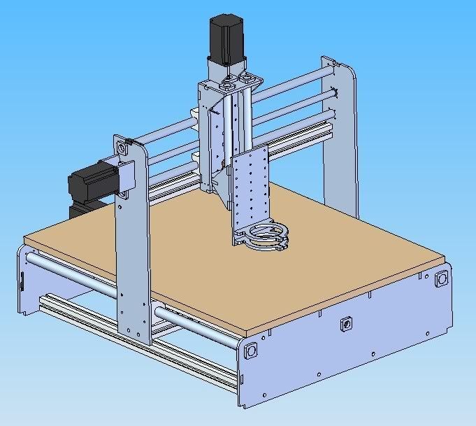
here is my design now..
I'm now going with an aluminum body as I have access to a mill so i might as well utilize it.
-
02-27-2008, 01:35 PM #6
Registered
- Join Date
- Sep 2003
- Posts
- 37
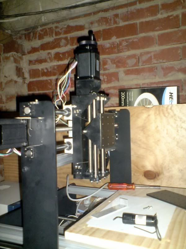
Just a quick update on where I am at (been going quite slowly)
The controller box is on its way

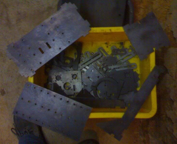
And I just picked up my box of laser cut parts today..


and this was the "final" design, I hadn't posted this up yet.

-
02-27-2008, 02:25 PM #7
Registered

- Join Date
- Aug 2005
- Posts
- 578
new design
djmickyg
Great looking start to you design.... Very professional.....However I saw a kink in you design....You will experience alot of flexing using the open face bearing design like you have it. It really needs to be closed on the Y axis as those bearings are designed to be used with downward force. Also the pipe or rod will also flex since it is not tied down along the axis...Just a note..... Again great looking design
Bob
-
04-13-2008, 07:52 AM #8
Registered
- Join Date
- Sep 2003
- Posts
- 37
Thanks for you advice, i see what you mean..
but it's to late to turn back now..
I don't plan on taking big cuts in anything to hard. so I hope it will be alright.
the build is going quite slow, so it will be a while before this thing is even cutting anything
-
10-25-2009, 01:21 PM #9
Registered
- Join Date
- Sep 2003
- Posts
- 37
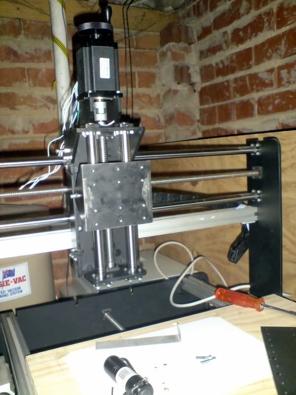
some updates.
It's been a while since I posted an update..
Most of the router is finished. all the axis' are working. ATM I'm just trying to sort out the stepper motors, they don't have much power at all.
I'm using the keling 425 oz-in pack with the 24v power supply.
The keling products get a good review on this site so I'm not sure why mine can be stopped so easily?

 http://mickgalt.blogspot.com
-
10-26-2009, 02:07 AM #10
Registered
- Join Date
- Jun 2009
- Posts
- 231
That's a really nice design.
-
10-30-2009, 09:15 PM #11
Registered

- Join Date
- Feb 2009
- Posts
- 1290
I really like this one as well.
What did the laser cutting cost? That is 1/4 inch plate?
-
10-31-2009, 12:57 AM #12
Registered
- Join Date
- Sep 2003
- Posts
- 37
the laser cutting was a freeby from a friend
 and it's 6mm
http://mickgalt.blogspot.com
and it's 6mm
http://mickgalt.blogspot.com

 Reply With Quote
Similar Threads
-
Newbie - To build or not to build Router/Plasma Table
By dfranks in forum Waterjet General TopicsReplies: 10Last Post: 04-08-2011, 05:16 AM -
starting a cnc
By clave in forum Mechanical Calculations/Engineering DesignReplies: 2Last Post: 08-02-2006, 07:55 PM -
New build starting soon.
By Kammo1 in forum DIY CNC Router Table MachinesReplies: 8Last Post: 03-23-2006, 09:25 PM -
Please Help me starting right!!!
By CrazyRonny in forum Uncategorised MetalWorking MachinesReplies: 32Last Post: 04-14-2004, 04:50 AM
