


I would like to know if a open pocket like the sample in this link can be programed in Mastercam X.
http://www.performancecadcam.com/dow...ntour%202d.pdf
I will be at a new company in a few months and need to learn a work around or a better way.
Thank You
Thread: open pocket
Results 1 to 20 of 21
-
06-23-2007, 10:28 PM #1
 Registered
- Join Date
- Nov 2005
- Posts
- 244
open pocket
-
06-24-2007, 04:12 AM #2
Community Moderator
- Join Date
- Apr 2003
- Posts
- 3578
Mastercam can do open pockets and has for years. it will even start outside the pocket if you want and overlap the open by a given amount that you want. Originally Posted by camtd

Get use to more control when you get into Mastercam over Surfcam.(Note: The opinions expressed in this post are my own and are not necessarily those of CNCzone and its management)
Cadcam
Software and hardware sales, contract Programming and Consultant , Cad-Cam Instructor .
-
06-25-2007, 11:48 AM #3
Registered
- Join Date
- Nov 2006
- Posts
- 367
Camtd,
Watch this it is a v-9 sample of open pocket, it works the same in X.
http://www.cad2cam.net/open%20poc%20v9.html
Steve
[email protected]www.cad2cam.net
Programmer/ Certified Cam Instructor
-
07-12-2007, 04:19 AM #4
Registered
- Join Date
- Nov 2006
- Posts
- 367
Camtd,
Is thepart on the video what you were looking for?
Steve
www.cad2cam.netwww.cad2cam.net
Programmer/ Certified Cam Instructor
-
07-12-2007, 06:43 PM #5
Registered
- Join Date
- Jul 2007
- Posts
- 60
Steve,
That was helpful to me. I'm using X2 and have had problems as well with open pockets... but with closed contours. Unfortunately, can't post a drawing of my part right now.
Imagine a square base with a circular boss on it. I can't seem to get Mastercam to pocket outside and around rather than the inside of that closed contour. If I select the face (and both closed contours) Mastercam just does not seem to pocket it very well. Especially if the boss contour has any complexity to it. Any thoughts?
Thanks
-
07-12-2007, 09:34 PM #6
Registered
- Join Date
- Nov 2006
- Posts
- 367
M30,
Are you using face toolpath? If so don't, in the pocket toolpath there is face button this works the best with closed contours, look for this at the bottom of pocket parameters page ( same place I turned on open pocket in V-9 video above) it says face then chain both closed contours. the cutter will overlap the outside of the block but will not violate the boss, it should not matter the complexity of the boss shape it will cut it. I use this in X2 all the time.
Hope this helps,
Steve Arteman
www.cad2cam.net
[email protected]www.cad2cam.net
Programmer/ Certified Cam Instructor
-
07-13-2007, 02:11 AM #7
Registered
- Join Date
- Jul 2007
- Posts
- 60
Steve,
Thanks for the tip however I was already doing as you suggested.
However, I did find something that solved my issue. I was using the spiral roughing cut method which gave the boss a bit of a elliptical trait -- Leaving way too much material on one side. All the other cutting methods were insufficient as well for one reason or another.
But, I changed to the morphing spiral and now it's creating a much nicer tool path. Don't know why I hadn't tried that one yet.
Cheers.
-
07-13-2007, 03:19 PM #8
Registered
- Join Date
- Nov 2006
- Posts
- 367
M30,
Yes very good selection, morph is made for what you are cutting I was going to put that on my last post but what you were describing didn't sound like you were using pocket face. The other thing I wanted to say is if you have finish off within the pocket face toolpath you will leave extra stock on areas as well.It will also leave extra stock on stepover control if you play with the tool step over percentage this will help too. Hopefully soon we will see true stock recognition in Mastercam.
Steve
[email protected]
www.cad2cam.netwww.cad2cam.net
Programmer/ Certified Cam Instructor
-
07-13-2007, 04:55 PM #9
Registered
- Join Date
- Jul 2007
- Posts
- 60
Ribs and surface pocketing
This is a little off-topic, but the one thing that is really kicking my butt on this part is the ribs using only 3 axis. I played around with surface pocketing with a ball-nose end mill. Running the verify it left a very choppy finish.
So I thought about using a 30 degree chamfer mill which is the same angle as the ribs. Then using a profile operation with a 30 degree taper. That sort of works, I just can't get the operation to align with where the ribs are supposed to be. Turning off tool compensation helped, but it still off by .25" or so and cuts material it is not supposed to. I've played with the top of stock offset quite a bit to try and get it to align.
Any ideas on that one?
-
07-16-2007, 09:59 PM #10
Registered

- Join Date
- Apr 2003
- Posts
- 103
You should try a "Surface Finish - Steep" op on those faces to clean them up after you've roughed out most of the material. They appear to be more or less exactly what that routine was designed for. You should end up with long tool paths going up and down the steep face to knock down the ridges left from the z level roughing.
Or, I suppose you could use a Surface Finish - Scallop routine and define the maximum scallop height you'll accept, though I would think that would end up creating many more tool paths than the Steep routine. But it's another tactic to look at.
That's the nice thing about Mastercam, there are about 40 different ways to do any given part.Ryan Shanks - Logic Industries LLC
http://www.logic-industries.com
-
07-17-2007, 01:31 AM #11
Registered
- Join Date
- Jul 2007
- Posts
- 60
Thanks for the tip, I'll try that. I'm curious if that will leave a very good finish?
I suppose, if I really wanted to get the best finish, I could get an adjustable vise so that I can make the chamfer face parallel with the horizontal plane. Then finish it with a face mill... Seems like a lot of work though.
-
07-17-2007, 06:06 AM #12
Registered
- Join Date
- Apr 2003
- Posts
- 103
The key to a good finish is to calculate (or let the software calculate) the scallop height for a given step-over.
Determine what finish is acceptable to you, and then back calculate it given the tool tip/edge radius to find the maximum allowable step-over.
That's pretty much it. Find the roughest finish you can deal with, and then find the step-over that will give you that scallop height or less. Easy Peasy.
You could use a rotab and four index points, or you can fixture the part five times and cut it with a face mill, but that's a lot of extra set-up time to do something that you should be able to cut satisfactorily with three axes in one set-up.Ryan Shanks - Logic Industries LLC
http://www.logic-industries.com
-
07-17-2007, 09:47 PM #13
Registered
- Join Date
- Nov 2006
- Posts
- 367
M30,
Finish blend might be a good finish toolpath for the part as well. If you would like send me the part and I will take a look at it. I may post up a short video of what I did on my site. send it to [email protected]
Steve
www.cad2cam.netwww.cad2cam.net
Programmer/ Certified Cam Instructor
-
07-24-2007, 07:06 PM #14
Registered
- Join Date
- Jul 2007
- Posts
- 60
Well, I ran the part on some machinable wax. I used the surface finish scallop and it did the job, but I was hoping for a better finish. I could reduce the scallop height more but it was already at .005". Maybe I am expecting too much. I'm new to CNC milling and have yet to learn all the limitations.
I saw the video on surface blend Steve, and while informative, I just couldn't get it to work for me.
-
07-24-2007, 09:11 PM #15
Registered
- Join Date
- Nov 2006
- Posts
- 367
M30,
Send the part if you would like and I will see what I can come up with. If you can't I will try to duplicate the picture when I have some free time. And run a video.
Steve
[email protected]
www.cad2cam.blogspot .comwww.cad2cam.net
Programmer/ Certified Cam Instructor
-
07-24-2007, 09:32 PM #16
Registered
- Join Date
- Jul 2007
- Posts
- 60
Thanks Steve.
I'll attach the part when I get a chance, but don't spend too much time on it - it's just for practice. Ultimately, the problem may be another issue which may be messing up the finish: No circular interpolation in G-Code
-
07-24-2007, 10:33 PM #17
Registered
- Join Date
- Jul 2007
- Posts
- 60
Thanks for taking a look:
-
07-25-2007, 02:35 AM #18
Registered
- Join Date
- Nov 2006
- Posts
- 367
M30
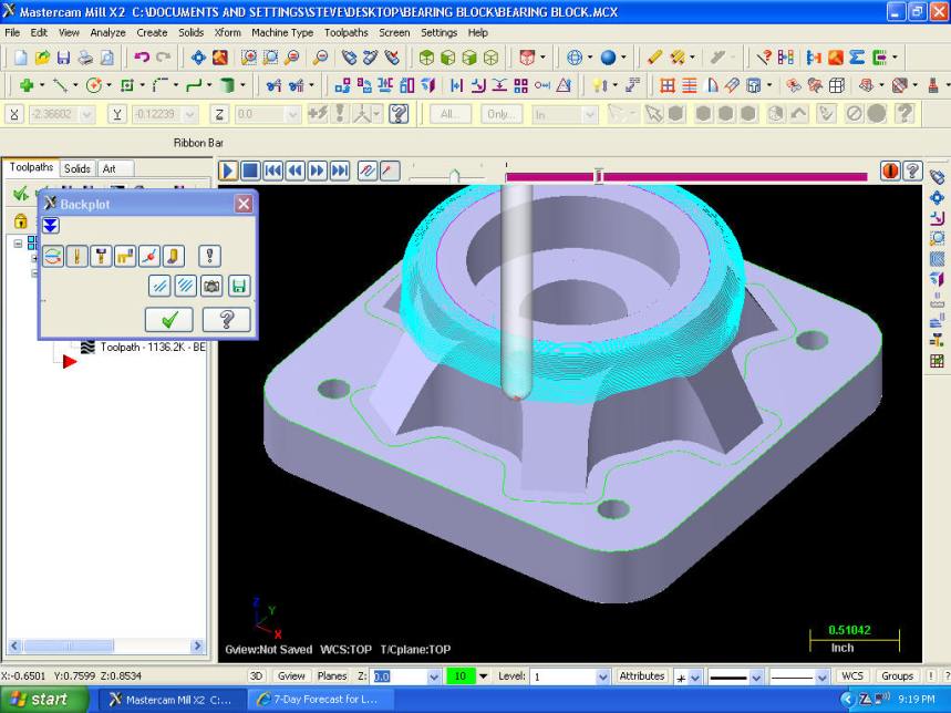
do scallop but using the top outside circle as a chain and the bottom edge with ears as chain. seem to work better if chains start from same point. go to www.cad2cam.net/bearing.htm
Steve
www.cad2cam.blogspot.com
www.cad2cam.netwww.cad2cam.net
Programmer/ Certified Cam Instructor
-
07-25-2007, 03:34 AM #19
Registered
- Join Date
- Nov 2006
- Posts
- 367
Here is the blend, This is a much cleaner toolpath and getting arc moves.
or www.cad2cam.net/blend.htmwww.cad2cam.net
Programmer/ Certified Cam Instructor
-
07-25-2007, 03:42 AM #20
Registered
- Join Date
- Jul 2007
- Posts
- 60
Thanks Steve. I was not selecting the top outside circle as the chain. I'll give that a try.

 Reply With Quote
Similar Threads
-
G77 Circular Pocket
By Big John T in forum BobCad-CamReplies: 3Last Post: 02-27-2007, 05:33 PM -
Complete Pocket PC DNC
By BigBobH in forum News AnnouncementsReplies: 0Last Post: 02-17-2007, 11:28 PM -
Open Pocket
By camtd in forum EdgeCamReplies: 2Last Post: 10-23-2006, 07:09 PM -
Pocket help
By tt_raptor_90 in forum MastercamReplies: 14Last Post: 06-20-2006, 03:37 PM
