


Don't you Dare!.. :withstupi I allready "messed up, note the small recess in the top of the vertical columnOriginally Posted by higgrobot

(forgot Radius comp...
)
Just "Dreamt up" i'm gonna fit some small nozzles around the milling motor, and use compressed air as a coolant, and also to blow away Chips, since Chip buildup in pockets and holes can ruin surfacefinish.. how's that?..
Since i also want to make a casing around this machine, i might even install a vacuum cleaner, to suck out all chips small enough to fly around ( i.e. Chips from finishing, more like dust than chips )
Results 21 to 40 of 438
-
01-16-2007, 12:03 AM #21
 Member
- Join Date
- Jan 2007
- Posts
- 352
-
01-16-2007, 09:19 AM #22
Registered
- Join Date
- Dec 2006
- Posts
- 68
Sometimes they're called Strap Clamps or Machinists Clamps I just call them Clamps, you can call them Toolmakers Clamps if you like Originally Posted by arie kabaalstra
Do you mean these thingies?:
-
01-16-2007, 10:07 AM #23
Registered
- Join Date
- Jan 2005
- Posts
- 224
out West here (between OK Corral & Sam's Shoot 'em Up Bar) we call them thar thangs "toe clamps"
-
01-16-2007, 10:23 AM #24
Registered
- Join Date
- Dec 2006
- Posts
- 68
Pulls out a big clamp from his back pocket and says 'That's not a Toe Clamp, This is a Toe clamp'
-
01-16-2007, 03:50 PM #25
Registered
- Join Date
- Mar 2004
- Posts
- 1306
Lovely Work Arie.
Just a question, why did you put the X axis Rails on the saddle and the trucks on a small table, rather than opposite?
If you put the rail undneath the table, you would have a larger table for the same travel, the X rails would be covered, and the total material required would be the same.Regards,
Mark
-
01-16-2007, 07:56 PM #26
Member
- Join Date
- Jan 2007
- Posts
- 352
Ok.. i think that i don't need to worry 'bout my english, but words like "toe clamp" weren't taught in school Originally Posted by Pres
Toe Clamps... Ok.. i Cut off a length of Tool steel ( 2510, almost similar to D2 ), later this week i'll be milling some "baby toe clamps" in Dutch these Things are called "Kikkers" (lit. "Frogs". they never jump, don't ask why )
I see what you mean, a bit like the Sieg X3.. that's just what i DIDN'T want.. dirt wil be no problem since i 'm going to fit some kind of Bellows ,and the Threadholes are blind, from the bottom, so even if there's chips on the guides, who gives a *!&%#?? Originally Posted by RotarySMP
Stability is also an issue here, i want the most stability, considering the work i want to do on this machine, things like this:
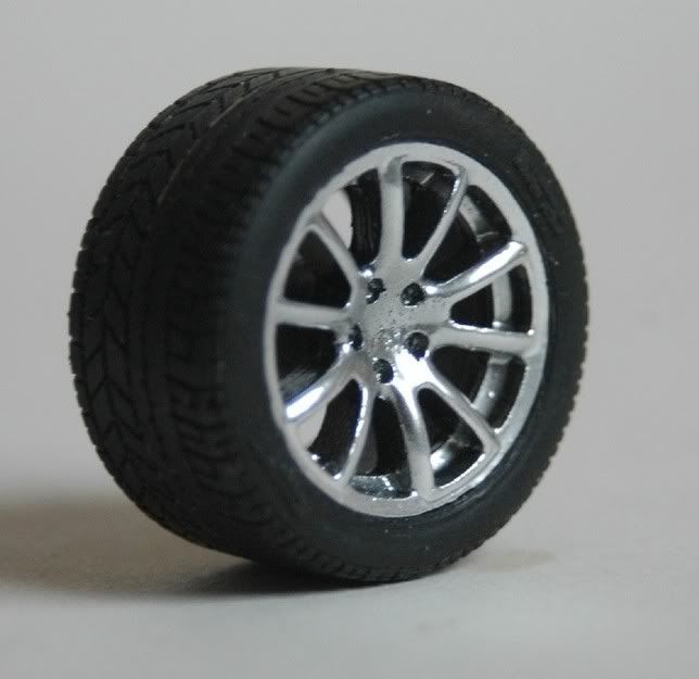
most CNC machines are built this way, if i'd want longer travel, i'd have built a Bigger machine!.. the runnerblocks of the Table are far apart, (center to center 220 mm on a 280 mm table, No overhang)
as said earlier, stability is what i need, the weel on the picture is only 21 mm ( less than an inch about 7/8" )
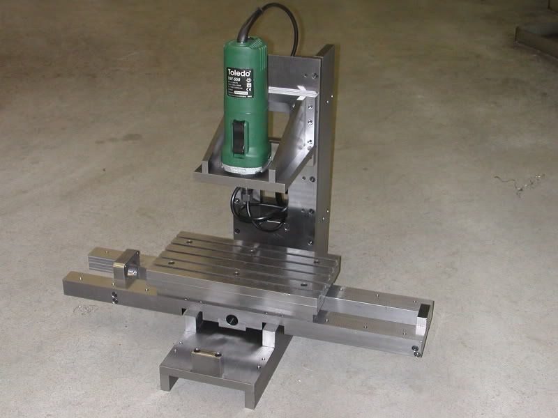
Today, i have been working on the head..
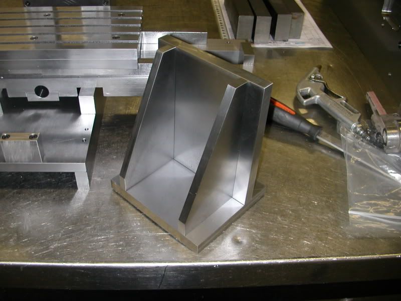
all parts Ground flat, and machined to size... tomorrow will be Drilling-day.. drilling all the holes to put the parts together, i wil also bore out the hole for the motor.
Put on the machine, it looks like this
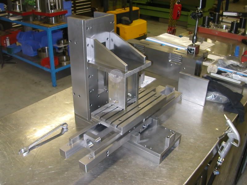
still no guides, but that's ok.. i'll have plenty of work wiring the motors and the PC, i also have to figure out how, how much, and were to put the end/limit/home switches.
I also wil buy a 4th controller, and a stepper motor to use as a 4th axis, i want to be able to mill my own model tires some day..( and numerous other parts )
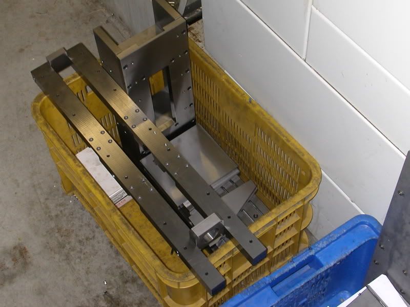
this finally, is a daily routine.. clearing up my workbench tomorrows work starts at 7.00 AM, and i dont want to start on a messy workbench, so every day for the past few weeks, all the parts of the CNC are put in this Yellow plastic Crate, waiting 'til 4.00 PM when i start working on mij little CNC again..
-
01-16-2007, 10:41 PM #27
Registered
- Join Date
- Mar 2003
- Posts
- 2139
It's an awesome machine. Originally Posted by arie kabaalstra
Is the above m/min or mm/min? If it's m/min it's going to be tough getting that axis moving that fast on the drives you are using. I would say your speed will max out at around 150-200 mm/min being that the drives max voltage is 30 volts, using any reasonable pitch ball screw, and coupling them to the lead screw directly.
EricI wish it wouldn't crash.
-
01-16-2007, 11:51 PM #28
Member
- Join Date
- Jan 2007
- Posts
- 352
the speeds in the Qoute are the rotation ( cutting ) speeds, not the table feeds
i had my steppers run @ 22Khz, which gives me about 800 revs on the steppers, with a 2 mm pitch on my leadscrews that'll be around 1.6 M/min or 1600 MM/min table feed on 12Vdc.. needless to say these values will increase with higher voltages..
also, i can always fit "heavier motors".. as long as they're Nema 23 Bipolar ones
-
01-17-2007, 01:55 AM #29
Registered
- Join Date
- Mar 2003
- Posts
- 2139
My apologies, in my post above I did mean 1500 - 2000 mm/min, not 150-200, so I guess I was fairly close.
Usually heavier motors are not necessary as they are often slower. Looks like the drive current capability will be a limiting factor here anyways. Bump up the voltage as high as you can safely go for more speed if you need it later.
It's a nice build.
EricI wish it wouldn't crash.
-
01-17-2007, 04:12 PM #30
Registered
- Join Date
- Mar 2004
- Posts
- 1306
Thanks for the answer Arie.
Are you going to grind you own spindle or buy something off the shelf?Regards,
Mark
-
01-17-2007, 09:00 PM #31
Member
- Join Date
- Jan 2007
- Posts
- 352
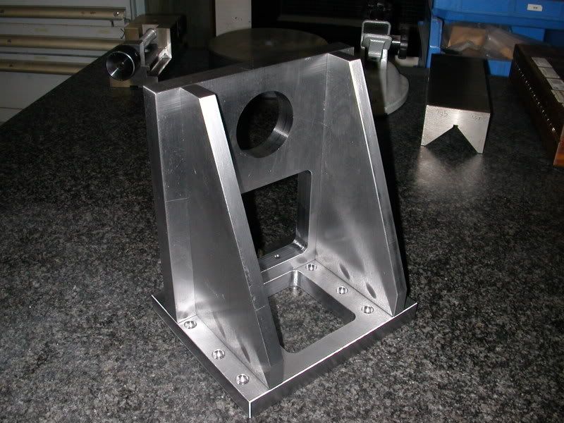
Now What?.. a High precision Bookend?..
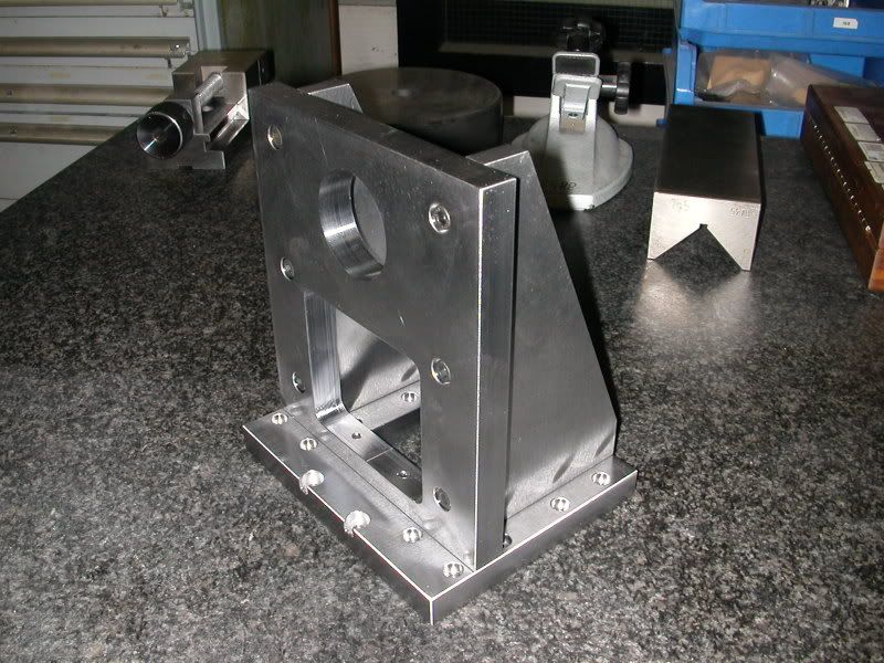
Nope.. the head is 'bout finished, only the Clamping for the motor has to be done, and the Nut Brackets for Z and X axis are still to be made..
This is what i got now... almost done, but still a lot to do..
I just bolted on the head, bolts of the vertical ribs are on the same offset, so there wil be no warping under heavy loads.
I will order Bosch Rexroth Ball screws and Ball Rail with 12 Runnerblocks.
Milling motor is a standard router, it'll have to do until it fails..
if the router isn't what i expect, then the design has enough room to incorporate another setup, i can place a motor further to the back ( decreasing cantilever effect ), or i can try another brand of routers.. the bottomplate is removable, so other designs can be tested easy..
@ Balsaman, no worries.. we all do make mistakes sometimes..
if the machine can reach 1200mm/min, it'l mill out that wheel i posted earlier in just 3 hours.. at 0.2mm stepover... i want a smooth finish..
-
01-17-2007, 10:28 PM #32
Registered
- Join Date
- Jan 2006
- Posts
- 481
hi
that is one fine machine
beautiful machine work , when are you taking orders
cheers
-
01-17-2007, 10:50 PM #33
Registered
- Join Date
- Oct 2005
- Posts
- 26
first CNC
This is a great machine.
It is nice to have a lot off machine to build this
I most do everthing by hand , it is also nice to do
But can not do so must als you
fred
-
01-17-2007, 11:01 PM #34
Member
- Join Date
- Jan 2007
- Posts
- 352
Orders?... well.. as soon as i sorted out all "problems i have yet to encounter", i will "clean up" all my drawings, adding Tolerances and reference planes. Originally Posted by FPV_GTp
convert em to PDF and DXF, write a little manual, and Burn the lot on a CD wich will eventually be for sale through my website : www.pure-scalemodels.eu
till then, you just have to be patient...
hopefully i will be able to order the guides and Ballscrews in a few weeks from now, in the mean time i will be wiring up the steppermotors, and the electronic handwheel, and also designing a 4th axis.
-
01-18-2007, 06:59 PM #35
Registered
- Join Date
- Aug 2004
- Posts
- 98
looks really impressive! Excellent work thus far, is the under side of the it cross braced at all? Being all steel I am sure it is plenty fine, thats my only suggestion is running something diagonal for extra support. Keep up the great work!
-
01-18-2007, 07:58 PM #36
Member
- Join Date
- Jan 2007
- Posts
- 352
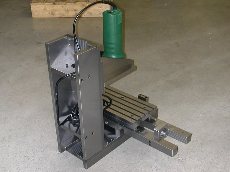
a Cross-brace has crossed my mind..
the only "bracing" now is the Motorbrace at one end, and the Spindle bearing brace at the other... but, the slide frame is also more or less braced bij the table, becaus 2 runnerblocks always stay over the middle of it when the table is at one end, and 4 runners are over the middle if the table is in the middle.. there is however some room left beside the y-axisguides to bolt a brace underneath at both sides..
since the design is very compact ( total height of table and cross-slides is under 100 mm ( 4")), the X-axis Spindle nut has a 2 mm clearance over the other parts..
-
01-18-2007, 09:12 PM #37
Registered
- Join Date
- Mar 2003
- Posts
- 2139
Very nice. My guess is the spindle will be the limiting factor for heavy materials. It will be a great spindle for the little wheels you want to make.
EricI wish it wouldn't crash.
-
01-18-2007, 09:38 PM #38
Member
- Join Date
- Jan 2007
- Posts
- 352
the spindle i choose is a normal router, it can take quite a lot of momentum, since the tools for machining wood ( its normal purpose) are quite long, thus generating a lot of momentum.. if it can withstand that kind of force, i think it will even do hardened steel.( not that i intend to, but just in case...)
i did a "test cut" with a standard HSS end mill, 3 mm @ 32000rpm ( cuttingspeed 300m/min) it will "eat" thermoplastics with hardly any burrs..
this is very nice, because this will enable me to make Sheet Styrene model kits.
To do this, i will glue a sheet of styrene ( evergreen ) onto a Nylon plate, with a waterbased glue, bolt the lot on my machine, mill out the contours and Hey presto!!,, parts like brakediscs, wheel spacers, or small parts to create assemblies, like why not even ship models?... mill out the bulkheads, and cover the lot with styrene sheet..
-
01-19-2007, 09:30 AM #39
Registered
- Join Date
- Oct 2005
- Posts
- 162
2 Things i wish to say/ask:
1. WOW! i'll be keeping an eye on this thread and see how well you go. An absolutely fantastic job so far, So keep up the fine craftsmanship!
2. When you talk about construction steel, i presume you are referring to high tensile steels? (eg 4140, 4340, etc) am i right?On the other hand, You have different fingers.
-
01-19-2007, 02:50 PM #40
Member
- Join Date
- Jan 2007
- Posts
- 352
the construction steel i use is a "plain ol' carbon steel"..
C45 is a steel with 0,45% Carbon, with a tensile strength of about 600 N/mm²
the Cold rolled quality i use is quite precise as it comes to dimensions, i usually don't have to grind of more than 0.05 mm on each side to get it perfectly parallel..
( i could also get flat ground quality, but i'd have to order that, insead of just Jankin' the lot from the steel rack )
it's a pity that there isn't an international materials specification.. for instance, the steel americans call "D2" is called 1.2397, Sverker21, or K110, the last two being factory names from Uddeholm and Böhler.
4140 is a bit like some steel i used for machine parts.. a manganese alloy, nice material. but, since factories like DMG, Bridgeport Mazak, Mas, and all the others i forgot to mention, cast their machineframes from iron, why should i bother myself with alloysteel for a machine?.. that's why i use this steel, it's tough enough to handle the stresses, doesn't vibrate that much, and Ridgidity is provided through the construction of it all.. ( box-like sections ) ..
Just got word that somewhere next week, my guides and ballscrews are going to be ordered... Progress!!!

 Reply With Quote
Similar Threads
-
more progress..
By adam_m in forum DIY CNC Router Table MachinesReplies: 0Last Post: 11-26-2013, 03:56 AM -
Design In Progress
By JoeDawg in forum Uncategorised MetalWorking MachinesReplies: 1Last Post: 10-07-2008, 07:48 PM -
My First Router Design & Progress
By watsonstudios in forum CNC Wood Router Project LogReplies: 40Last Post: 07-22-2007, 09:19 AM -
Looking into buidling an Auto-start RPC
By Wendell in forum Phase ConvertersReplies: 2Last Post: 10-12-2006, 03:03 AM -
Alibre design in progress
By xyzcnc in forum Uncategorised CAD DiscussionReplies: 10Last Post: 06-07-2005, 06:49 AM
