


Hello,
I am in the initial design phase on my first build and have been putting a good deal of though into the bearings for my gantry. I think I have a pretty good idea going here and would love some feedback. I wanted to come up with a design that I could make using a table saw, drill press and router table (the kind with a fence and a hole in the table top, not a cnc). the bearings would need to be good enough get me up running and last long enough to mill their own replacements.
Here is what I have:
Attachment 253286 Attachment 253288
It will be made from Baltic birch ply scraps I have in the shop and run on 1" steel pipe. The two lower bearing assemblies will be glued in place and the upper will have pressure applied by the nut and bolt. the middle nut is a jam nut to prevent the adjustment nut from backing out. The bottom is open to allow for the pipe to be supported from below.
The advantages I see are as follows:
1. The materials are all free shop scraps other than the skate bearings.
2. I am sure I can quickly and accurately build these with the tools I own.
Potential problems:
1. The holes for the skate bearing axles will elongate.
2. The whole assembly may bow out at the bottom (they are tall to so that the flex point is wide to handle the sheer force)
Since this is my first build I have no idea how much force is on the bearings so I am not sure if these will be problems.
Results 1 to 13 of 13
-
10-16-2014, 12:08 AM #1
 Registered
- Join Date
- Oct 2014
- Posts
- 3
Reinventing the skate bearing cariage
-
10-16-2014, 12:16 AM #2
Registered
- Join Date
- Oct 2014
- Posts
- 3
Re: Reinventing the skate bearing cariage
The front and back plates will have guides for the skate bearing assemblies to keep them separated 120 degrees. these will be glued up like this:
-
10-16-2014, 12:41 AM #3
Community Moderator
- Join Date
- Mar 2003
- Posts
- 35538
Re: Reinventing the skate bearing cariage
To be honest, the "glory days" of "skate bearings on pipe" cnc routers ended about 7-8 years ago. Around that time, options started to appear that didn't cost much more, and were much better.
If you want the bearings to be as rigid as possible, than the bearings need to be extremely tight, almost to the point where they don't turn smoothly. Any less and it'll be sloppy. Unfortunately, this puts you into the range where your wood will deform. So you'll be limited on how tight you can set up the bearings.Potential problems:
1. The holes for the skate bearing axles will elongate.
2. The whole assembly may bow out at the bottom (they are tall to so that the flex point is wide to handle the sheer force)
Since this is my first build I have no idea how much force is on the bearings so I am not sure if these will be problems.
The other issue is that this design forces you to use unsupported pipe, which is the #1 cardinal sin of CNC building.
My machine and the Joes 2006 use a simpler, and much more rigid design. Use a torsion box to support the pipes, mount the bearings on aluminum angle, and use threaded rod (or a similar method to what you've shown) to pull (or push) the bearings together toward the torsion box.
Don't let me stop you from going through with your design. It'll be a good learning experience.Gerry
UCCNC 2017 Screenset
http://www.thecncwoodworker.com/2017.html
Mach3 2010 Screenset
http://www.thecncwoodworker.com/2010.html
JointCAM - CNC Dovetails & Box Joints
http://www.g-forcecnc.com/jointcam.html
(Note: The opinions expressed in this post are my own and are not necessarily those of CNCzone and its management)
-
10-16-2014, 12:47 AM #4
Registered
- Join Date
- Oct 2014
- Posts
- 3
Re: Reinventing the skate bearing cariage
What are the options you refer to? I am open to any suggestion.
-
10-16-2014, 01:11 AM #5
Community Moderator
- Join Date
- Mar 2003
- Posts
- 35538
Re: Reinventing the skate bearing cariage
V Bearings on steel angle, or cnc routerparts skate bearing carriages.
Gerry
UCCNC 2017 Screenset
http://www.thecncwoodworker.com/2017.html
Mach3 2010 Screenset
http://www.thecncwoodworker.com/2010.html
JointCAM - CNC Dovetails & Box Joints
http://www.g-forcecnc.com/jointcam.html
(Note: The opinions expressed in this post are my own and are not necessarily those of CNCzone and its management)
-
10-16-2014, 01:42 AM #6
Registered
- Join Date
- Jun 2012
- Posts
- 108
Re: Reinventing the skate bearing cariage
I used the tools you have and I went down the road you are looking at. Here is where I posted what I did. http://www.cnczone.com/forums/diy-cn...-cnc-mill.html
Unsupported pipe/rails just flex to much to use. Maybe under 12 inches in length would be OK.
Good luck, and it is a fun build.
-
10-16-2014, 03:50 AM #7
Registered
- Join Date
- Sep 2014
- Posts
- 30
Re: Reinventing the skate bearing cariage
I used the gusseted corner bracket extrusion from 8020 and it works much better then the buildyourtools skate bearing design on MDO.
I will probably upgrade to a regular linear bearing setup eventually though
-
10-16-2014, 05:30 AM #8
Registered
- Join Date
- Jun 2012
- Posts
- 817
Re: Reinventing the skate bearing cariage
I'm one of the few who still believe that skate bearings on pipe can be a valid method, however it must be done correctly. The pipe must be supported. The bearings must be mounted rigidly with the ability to adjust them very snug and accurately. Wood bearing mounts won't work very well, but don't let me stop you. I made my adjustable bearing mounts from aluminum bar and am pretty happy with them. http://www.cnczone.com/forums/cnc-wo...lva-build.html
-
10-16-2014, 11:57 AM #9
Gold Member
- Join Date
- Jun 2004
- Posts
- 6618
Re: Reinventing the skate bearing cariage
Honestly I think the design for the carriages on pipe is far too complicated for what it produces. Less is often more and is true in this case. My router was built before CNC Router Parts came out. It uses an aspect if it's design though in that the bearings are held in aluminum bar. Mine does not pinch the flat bar like CNCRP's carriages do. This makes them a simpler design. You can see how I did mine in post 17 and 18 in this thread.
http://www.cnczone.com/forums/cnc-wo...tty-shark.html
Post 24 has a final layout drawing.
Flat bar is easier to work with and only needs support in one direction really. That support effectively braces it in all directions. You could make some of these parts out of wood without having it effect the overall strength of the system like the tri-trollies might.Lee
-
10-16-2014, 02:21 PM #10
Registered
- Join Date
- Sep 2014
- Posts
- 30
Re: Reinventing the skate bearing cariage
I used this extrusion from 8020 (metric version of 10 series was less expensive)
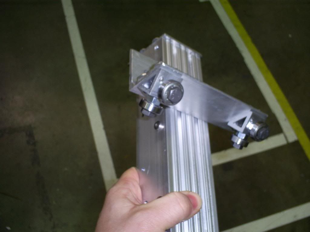
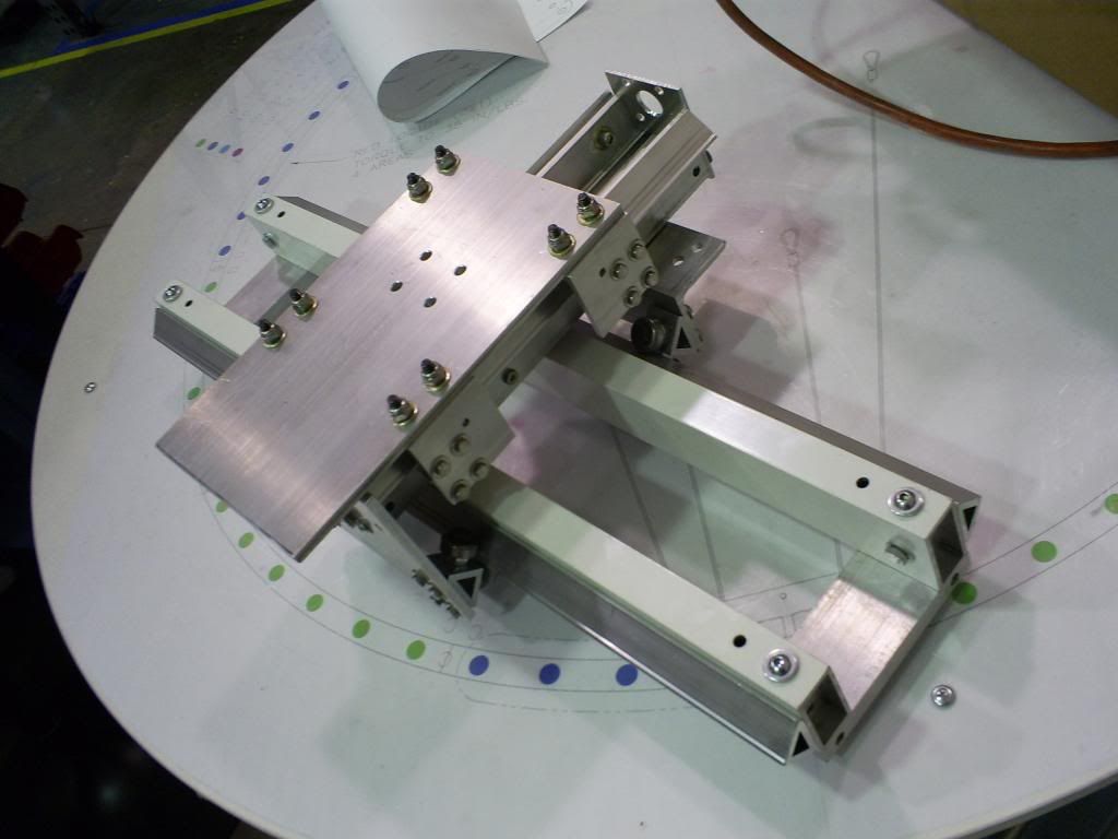
And it moves really smooth.
3 axis router gantry assembly - YouTube
-
10-17-2014, 02:49 AM #11
Gold Member
- Join Date
- Jul 2003
- Posts
- 196
Re: Reinventing the skate bearing cariage
My 4th machine had MDF bearings riding on gas pipe that was fully supported using aluminum channel. The machine worked good. I outgrew it. http://www.cnczone.com/forums/diy-cn...e-cnc-4-a.html
jgrohttp://jgroshoppages.blogspot.com/
-
10-17-2014, 05:48 PM #12
Gold Member
- Join Date
- May 2005
- Posts
- 3920
Re: Reinventing the skate bearing cariage
I like this flat bar approach. It should be easy to work with in a limited wood working shop. I took a quick look at your photos and I do wonder if there is provision to prevent lifting?
The nice thing about this approach is that you can build a robust base and upgrade it later when time and money permit. Even with a wood structure you should be able to rigidly support the bearings.
 Originally Posted by LeeWay

-
10-17-2014, 06:14 PM #13
Gold Member
- Join Date
- Jun 2004
- Posts
- 6618
Re: Reinventing the skate bearing cariage
If you look at the end diagram, you can see two black pads on the bottom of the gantry. There are actually 4 delrin pads shimmed snugly up against the bottom of the flat bar. This prevents any lift.
You can just make them out in this image. They are mounted on the red iron gantry cross braces.
Lee

 Reply With Quote

Similar Threads
-
New skate bearing idea
By grumpygeek in forum DIY CNC Router Table MachinesReplies: 0Last Post: 06-12-2013, 02:49 PM -
Skate Bearing Slides
By Wolfspaw in forum Linear and Rotary MotionReplies: 3Last Post: 01-24-2012, 11:22 PM -
Skate Bearing Blocks?
By thebluedirt in forum Linear and Rotary MotionReplies: 12Last Post: 02-08-2009, 02:59 PM -
Lifespan of a Skate Bearing.
By Miata2k in forum DIY CNC Router Table MachinesReplies: 9Last Post: 09-22-2006, 06:53 PM -
Skate Bearing Design
By coolman in forum DIY CNC Router Table MachinesReplies: 11Last Post: 05-20-2005, 07:25 PM
