


I just ordered the plans over the weekend and all I can say is WOW, Bob, the plans are so well done and complete I almost feel like Im stealing them at the price you're selling these! Seriously, I have bought other plans in the past but these are really really nice.
I have already started to collect parts, placing orders like a madman yesterday. I have most of the specialty hardware coming, all the metal and I already have the electronics so as soon as parts start arriving I can get going.
In the meantime I have been pouring over the plans and getting acquainted with everything. Im building this machine to help me build another machine. A practice that seems to occur often here on the Zone from what Ive read.
I want to be able to mill some small aluminum parts for another cnc build Ive got planned and the Momus seems to be just the ticket to do that in moderation of course.
Hopefully Ill have some build thread photos soon and dont be surprised if I call on some of you for help with this, looks very interesting to say the least!!
Jim
Thread: New Momus Build
Results 1 to 20 of 81
-
09-17-2013, 01:28 PM #1
 Registered
- Join Date
- Jun 2009
- Posts
- 267
New Momus Build
-
09-18-2013, 03:45 PM #2
Registered
- Join Date
- Jun 2009
- Posts
- 267
Parts!! I got parts!! Hey it isnt much but I did get a few things from Mcmaster Carr today so its officially ON!!
Got my 3/8" acme rod and the two timing belts. Im excited to get going.
-
09-18-2013, 04:06 PM #3
Registered
- Join Date
- May 2012
- Posts
- 22
Have fun !
The first parts I built were the travel arms for the gantry, and they were the last parts I installed. Felt real good.
-
09-24-2013, 02:22 PM #4
Registered
- Join Date
- Jun 2009
- Posts
- 267
Anyone got a few tips or tricks for fabbing part #10, the belt clamp? I tried the double hacksaw blade approach and I'm not sure if my blades were a little dull or what but it didn't turn out very good at all. Just wondering how some of you went about it.
Sent from my iPad using Tapatalk - now Free
-
09-25-2013, 01:20 AM #5
Registered
- Join Date
- Aug 2013
- Posts
- 35
could you clamp the aluminium part in a small wooden jig with a moveable guide plate and use a small bit in the router at shallow cut depths to gradually make the required groove?
-
09-25-2013, 03:07 AM #6
Registered
- Join Date
- Mar 2013
- Posts
- 209
It's not that hard to do with a hacksaw, I found it actually easier to do with two used/dull blades because they wouldn't cut that quickly and leave you more room for adjusting your movements. I made the y-axis belt plate twice because I ended up repurposing that part as a proximity switch target, so my second one was a little bit bigger in height.
Just take it slow, here's what my routine was (assuming that you are right handed). Clamp the part in the vice and set the finger nail of your left thumb against the left scribed line of the groove you want to make. With your right hand and the hack saw set the saw down on the part with the blade all the way extended away from you and resting slightly against your finger nail - sitting on the edge at about 30deg. Then pull the saw gently towards you to make an initial notch into the edge of the part that is facing away from you. Perhaps even do it a second time. That'll give you the starting point for the cut. The rest is just making consistent back and forth movements with the saw trying to keep it at 90 deg relative to the part and slowly setting the blade down to be cutting the upper face of the part in full. Keep watching the left line until the desired depth is reached.
I found that the belt wouldn't really fit in these groves as such, so I used a small triangle shaped file to open up the upper edges a little bit to accept the belt.
Again just take it slow and watch what the saw is doing / where it wants to go.
Also, it doesn't have to be all that pretty, it just needs to clamp the belt properly - cut a small piece of belt off and keep nesting it in there to see where you are, if it accepts it fully.
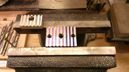
WP_20130902_002 by mkloberg, on Flickr
-
10-29-2013, 07:17 PM #7
Registered
- Join Date
- Jun 2009
- Posts
- 267
Hey guys quick question. The answer to this may be obvious but I just want to make sure so as to avoid any mistakes. When setting the studs into the z raiI (part #24) I can only assume they don't go in 1/2" deep like all the other studs therefor protruding out the back? I would guess they simply go flush with the back of the part or 1/4"? Also the stud that goes into part #22 the z cable plate, how deep does this one go in and protrude out the back of that part? I couldn't find where it really specified this in the plans, maybe I can't see the forest for the trees?
Sent from my iPad using Tapatalk - now Free
-
10-29-2013, 11:16 PM #8
Registered
- Join Date
- Mar 2013
- Posts
- 209
Correct, the studs in the z-rail have to be flush in the back. There is very little clearance behind the rail, so none of the studs should protrude out the back.
As for stud SG in the z-cable plate #22, I guess that should go in just enough for the washer and the nut to screw on securely at the bottom.
--
Mac
-
10-30-2013, 01:50 AM #9
Registered
- Join Date
- Aug 2011
- Posts
- 53
I made my belt clamp grooves by grinding a cutting tool to the shape of the belt groove. I put the tool in the mill and clamped the little aluminum part in the mill vice. Then a little at a time feed the quill down while you move the Y axis back and forth with the mill off, so it's just like an old style shaper. You can then move over to the next groove in the X direction and scrape out the next groove. That way you get a nice straight groove and with the correct pitch. It just takes a while.
I don't make mistakes ... I make 'unintended engineering design changes'.
-
10-30-2013, 03:37 AM #10
Registered
- Join Date
- Jun 2009
- Posts
- 267
Thanks for the tips guys, I recently finished all the metal parts and hope to start the wood portion this weekend. I'll post some pics when I have something worth posting. Right now it's just a pile of parts on a bench!
Sent from my iPad using Tapatalk - now Free
-
11-03-2013, 10:51 PM #11
Registered
- Join Date
- Jun 2009
- Posts
- 267
Ok a promised some progress pics. Gantry trial assembly is done and so far so good, everything seems to be coming together as planned. I only had a few minor glitches during assembly but nothing major other than the fact I made one part #27 I think it was, too short. I will have to r redo that one!
Sent from my DROID RAZR using Tapatalk 4
-
11-03-2013, 10:56 PM #12
Registered
- Join Date
- Jun 2009
- Posts
- 267
More pics
Sent from my DROID RAZR using Tapatalk 4
-
11-04-2013, 03:26 AM #13
Registered
- Join Date
- Mar 2013
- Posts
- 209
Awesome progress, the carriage and gantry parts look great. Very clean parts and looks like precision work, nice job & thanks for the pics!! :-)))
Won't be long now until you get your machine up and running, hehe...
I'm wondering about something though: Why did you drill four pin holes around the large hole for the lower 5/16-18 3" main carriage bolts on parts 17 and 16 (the two front carriage blocks)? There should only be two around that hole and the upper two main bolt holes on those two parts are missing their pin holes... Just wondering.
--
Mac
-
11-04-2013, 04:27 AM #14
Registered
- Join Date
- Jun 2009
- Posts
- 267
Well Mac we call that a mistake! Lol I put it together backwards the first time and had to redo that part of the assembly. Other than having the extra holes in there nothing was compromised so I did not remake the parts just drilled new holes. Worked out ok and the assembly is as square as my instruments will allow so I'm happy. I didn't buff and polish any of the parts like some I've seen and kinda of regret that at times but I'll get over it in time I'm sure. Hopefully I'll start wood fabrication tomorrow, I'm really getting excited now!!
Sent from my iPad using Tapatalk - now Free
-
11-06-2013, 12:16 AM #15
Registered
- Join Date
- Jun 2009
- Posts
- 267
So anyone else cut wood part R to 25" instead of 31"???? This dummy did!!......
-
11-06-2013, 01:34 AM #16
Registered
- Join Date
- Mar 2011
- Posts
- 144
measure (S) front cover before you cut it should be longer then plans shows. I had to attach piece of wood to makeup for the difference. I think it should be about 2" longer height wise.
-
11-08-2013, 04:33 AM #17
Registered
- Join Date
- Jun 2009
- Posts
- 267
Can anyone clarify the orientation of parts I and J......The square that is cut out for the motor is offset. Does the offset go to the inside or outside? I think if Im seeing it right its to the inside meaning the thinner side of the cutout faces the inside of the cabinet.
Am I right?
-
11-08-2013, 11:16 AM #18
Registered
- Join Date
- Mar 2011
- Posts
- 144
Yes, Your are correct . The thinner side of the cut (.188) faces inside.
-
11-08-2013, 03:47 PM #19
Registered
- Join Date
- Jun 2009
- Posts
- 267
Hey thanks, I thought as much but wanted to make sure before I screwed something up! Hope to have the base in primer today or tomorrow then its time to put the gantry on! Im getting closer!!
-
11-08-2013, 09:50 PM #20
Registered
- Join Date
- Jun 2009
- Posts
- 267
More progress. Got the base in primer today. Still need to fill some holes but pretty much done with it, ready for paint. Haven't decided on a final color yet...
Sent from my DROID RAZR using Tapatalk 4

 Reply With Quote
Similar Threads
-
It's Alive ! Momus 2.0 Build
By Cheeto in forum Momus Design CNC plansReplies: 28Last Post: 03-18-2014, 12:42 AM -
404's Momus V2.0 build
By e404_forbidden in forum Momus Design CNC plansReplies: 13Last Post: 09-22-2013, 02:49 PM -
Michael's Momus build
By Michael In Cali in forum Momus Design CNC plansReplies: 26Last Post: 05-14-2012, 10:38 PM -
Rob's Momus Build
By rwhittle in forum Momus Design CNC plansReplies: 8Last Post: 04-08-2012, 08:41 PM -
My Momus build
By TeslaFreakshow in forum Momus Design CNC plansReplies: 29Last Post: 12-06-2011, 11:35 PM
