


Few week ago I acquire a Bridgeport Boss 5 or 6 in a trade. Now the machine would move in the xyz axis using the stock control but I was unable to get the RS232 connection working for the machine. So I either had to use the teletypewriter to make punch tape or learn how to program line by line at the control panel. The teletypewriter was included with the machine.
The teletypewriter is now in the back of the truck for a trip the scrap yard. Screw using that thing. New plan is to update the machine with mach3, gecko 203v drives, and Candcnc electronics. In time I may change to PMDX-126 board due to spindle control. The only board I need to buy for my CandCNC electronics is the MTA150 due to spare cards I had for my plasma table.
Plan
Candcnc electronics : UBOIII, TABLE I/O card, MTA150 drive card
Modify the Bridgeport Transformer to supply 70v using a full bridge rectifier and the caps removed from the Bridgeport.
Gecko 203V drives
Windows XP
1 Ghz computer w/ Parallel port
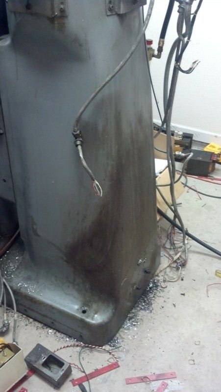
On to removing the old electronics. Took about a 5 hours to remove all the old stuff. Care was taken for the wiring and electronics, may need to buy less stuff later on.
Tape reader removed.
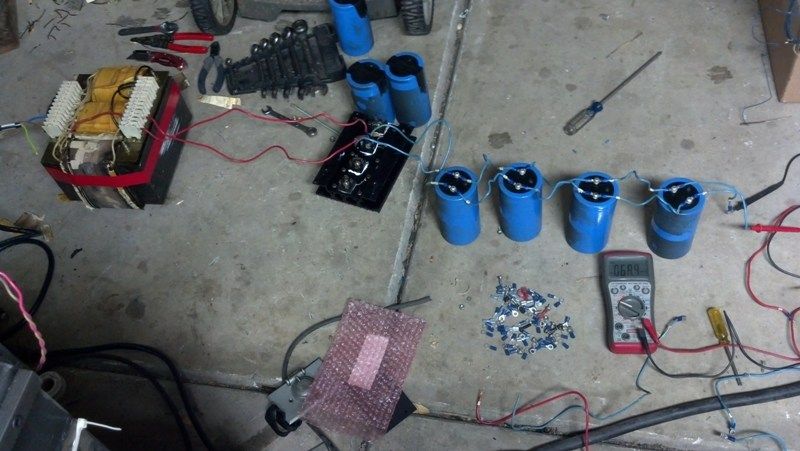
Caps removed. Will be saved for making the power supply.
Power supply and card cage removed.
Massive heat sink was on the side panel on the electronics cabinet. I will be saving the heat sink. That stuff is pricey.
- - - Updated - - -
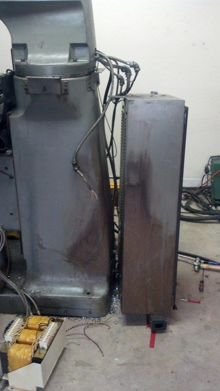
Side cabinet removed. The EMT conduit nuts caused a lot of swearing and smacking of the hammer. Never had a set refuse to unscrew like this set.
The teletype and side panel are already in the truck bed for a trip to the salvage yard tomorrow. The plan is to keep the power cabinet but move it to the side of the mill then insert all the electronics into the cabinet.
The plan for the weekend is the removal of parts for the electronics cabinet, relocation of cabinet and punch the holes to feed the motor cables and switches into the new cabinet.
Thread: Bridgeport Boss Retrofit
Results 1 to 20 of 30
-
11-22-2013, 03:42 AM #1
 Registered
- Join Date
- Oct 2010
- Posts
- 57
Bridgeport Boss Retrofit
-
11-24-2013, 07:53 PM #2
Registered
- Join Date
- Oct 2010
- Posts
- 57
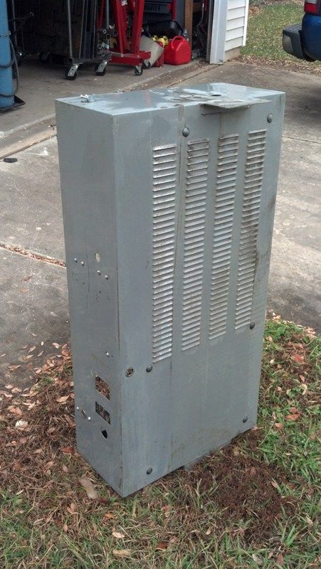
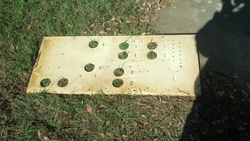
Rear cabinet removed.
30+ years of dirt and grime.
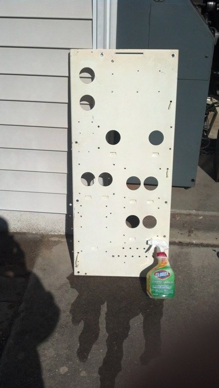
Cleaned
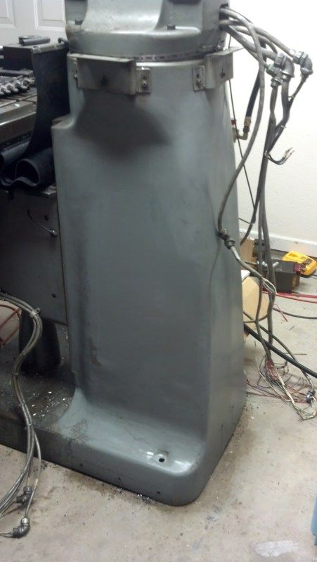
I attempted to clean the rear cabinet at a car wash bay. The grime refused to come off till I used Clorox cleaner. The Clorox cleaner worked magic on both the mill and the rear cabinet. Spray on and just wipe off.
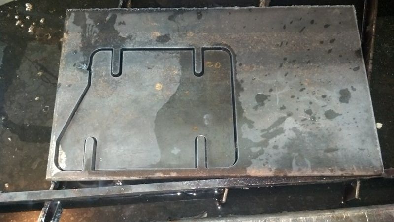
By using a 3/8" thick plate for the adapter bracket, I was able to mount the panel dam near vertical and level. Owning a plasma table comes in handy sometimes. The bolt spread is wider on the bottom of the mill versus the cabinet. Bracket is about 7.5in wide by 6in tall.
Mounted up. Excuse the mess on the mill table.
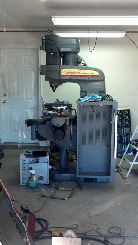
I will be remounting the cleaned panel into the cabinet to use the disconnect and a place to mount the computer, gecko drives and Mill electronics. Next update in a day or two will include how the transformer was modified to output 75V and the circuit to smooth out the DC power.
-
11-25-2013, 02:09 AM #3
Member
- Join Date
- Jan 2005
- Posts
- 15362
Shefron
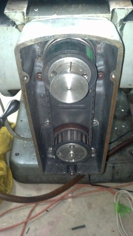
It is easy to tell if you have a Boos 5 or Boss 6, the Boss 5 the timing pulleys are 1:1 ratio, which you can see on the Y axes with the cover off, the Boss 6 has a 2:1 ratio
It's also better to use or put, the cabinet on the the back, gives you more room around the table, & away from coolant, chips EtcMactec54
-
11-25-2013, 03:04 AM #4
Registered
- Join Date
- Oct 2010
- Posts
- 57
Disclaimer: Electricity is dangerous and can kill if mishandled. Modifying transformers and using capacitors can result in death or serious injury.
Made some progress on the power supply for the gecko drives. I was shooting for 75 volts DC but over trimmed the coils on the transformer.
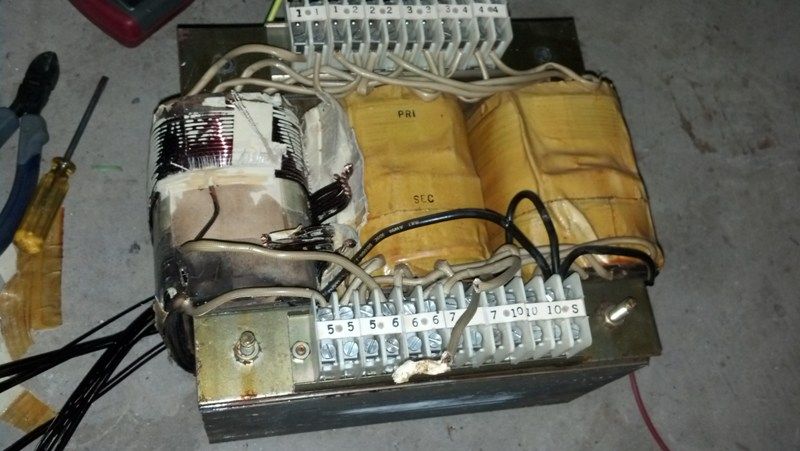
Testing of the power supply. About 70v Dc with very little AC ripple. Reused the Full-wave bridge rectifier, capacitors, and transformer from the Bridgeport to make the complete system. The system is missing a bleed down resistor for draining the capacitors when the system is off.
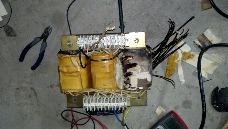
Still debating on redoing the transformer to get closer to 75volts since I have 2 spare coils on the transformer. I also need to glue the wire down to the transformer to avoid any trouble later on with a stray wire.
Bleeder resistor circuit options
1. A high ohm resistor that can be placed in parallel while the system is running. Probably will go this route. Will also help to stabilize the voltage output since there is always a load on the power supply.
or
2. Low ohm resistor in parallel but must be turned off by a relay when the system is running due to power draw with said resistor. I have a few 1 ohm 50 Watt resistors that were pulled from the Bridgeport. This will allow the caps to drain fast but I think to fast.
-
11-25-2013, 03:34 AM #5
Registered
- Join Date
- Oct 2010
- Posts
- 57
The machine is a Boss 5 it turns out. 1:1 pulley system when I removed the cover. Thanks for clarication on the difference between them. I knew about the pulley difference but for some reason it didn't clink to just take the cover off. Originally Posted by mactec54

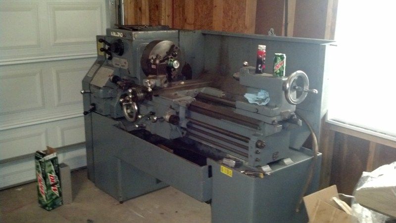
Ill have to give some serious thought to placing the cabinet in the back of the mill. Im running out of room in the 2 car garage due to a Plasma table that can cut a 5' by 5' plate and a lathe I also got at the same time as the mill. Throw in the 80 gallon air compressor and massive toolbox and you run into the space issue I have. I couldn't turn down a leblond 15x30 servo shift lathe and the Bridgeport boss 5 for a AR15 rifle. Nothing wrong with either but I helped a friend with his small business and he in turned gave me a sweet deal on the machinery instead of auctioning them off on his site.
Here is a pic of the lathe as it sits in my garage
-
12-09-2013, 06:01 AM #6
Registered
- Join Date
- Aug 2012
- Posts
- 113
I'm going to be keeping an eye on this as I am beginning a Series 1 rebuild that has an old TRAK CNC system.
-
01-07-2014, 04:39 AM #7
Registered
- Join Date
- Oct 2010
- Posts
- 57
Work on the mill as been progressing really well.
First the rules that I had to follow for the build.
1. No buying parts unless I earned the money off the table per the GF. -Not really going to complain about this one. She is better with money than I am and it will cause me less stress. In no way do I make alot of money off the table but I do have a full time engineering job.
2. Still need to spend some time with her on the weekends. - Propane garage heater to the rescue. Garage is a palmy 70-75 degrees so she can read her book in the garage or chat with me.[/COLOR]
Control system.
Here were the systems I was debating about for the control system. Rough pricing listed for anyone that is having the same issues
PDMX (can use linuxcnc or mach3) Limited I/O points
$174 PDMX-126 Breakout board
$57 PDMX-107 Isolated spindle control (controls VFD)
$200 Ethernet smoothstepper (Can be omitted) Way to avoid using the parallel port
$200 Mach3 License (Already own a copy for my plasma table.)
Mesa Card setup (Linuxcnc only)
5i25 PCI card
7i76 breakout board (controls 5 steppers, spindle encoder, isolated analog spindle speed control, 48 I/O points.)
$200 for plug-in-play setup.
I went with the mesa card setup for the massive amount of I/O points and the option to run 5 axis's from one card. Plus later on I may decide to add a encoder to the spindle to allow for rigid tapping. The PDMX can be expanded to that many I/O points with another card.
Linuxcnc can be a little scary at first but is fairly easy to get started with the new GUI setups that are included for the Mesa cards.
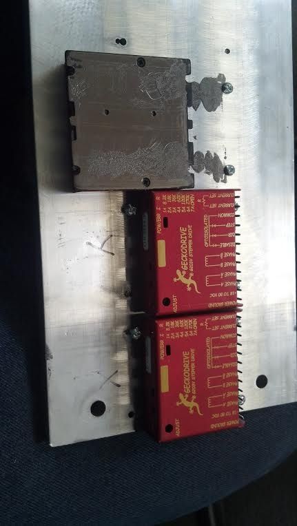
Geckos 203v mounted to a 1/2 slab of Aluminum which is bolted to one of the original heat seaks. The wiring is little bit of a mess at this time but should be cleaned up after this weekend. Later on I will mill a new slab that will include fins on the bottom for the geckos. Sounds like a good starter project.
The wiring TB's were pulled from the original wirig to save on costs. Also reused alot of the original wiring for connecting stuff. Tons of 20, 18, 14, 12ga wires. I would say this saved at least $100.
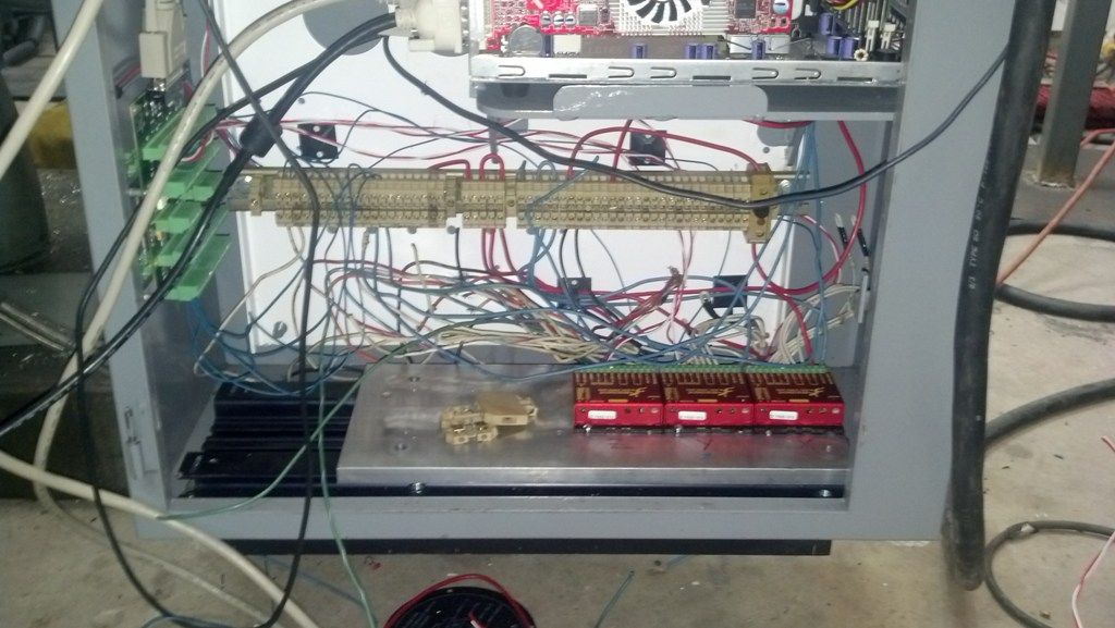
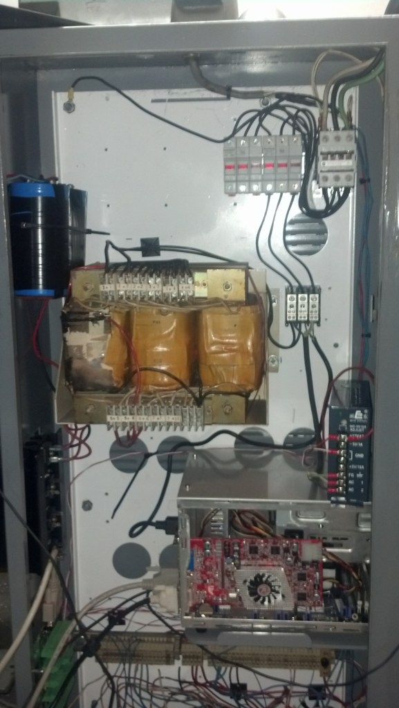
Cabinet
Top left space reserved for Hitachi WJ200-015LF VFD
Top right - Fuses and a 40amp contactor
Middle - Transformer for the 70volts dc and the caps are sitting off to the left. I will make a new shelf this weekend to mount the caps.
Computer is mounted to a custom made shelf. A shuttle PC fit in the cabinet really well. Computer is not fully setted on the shelf during pictures.
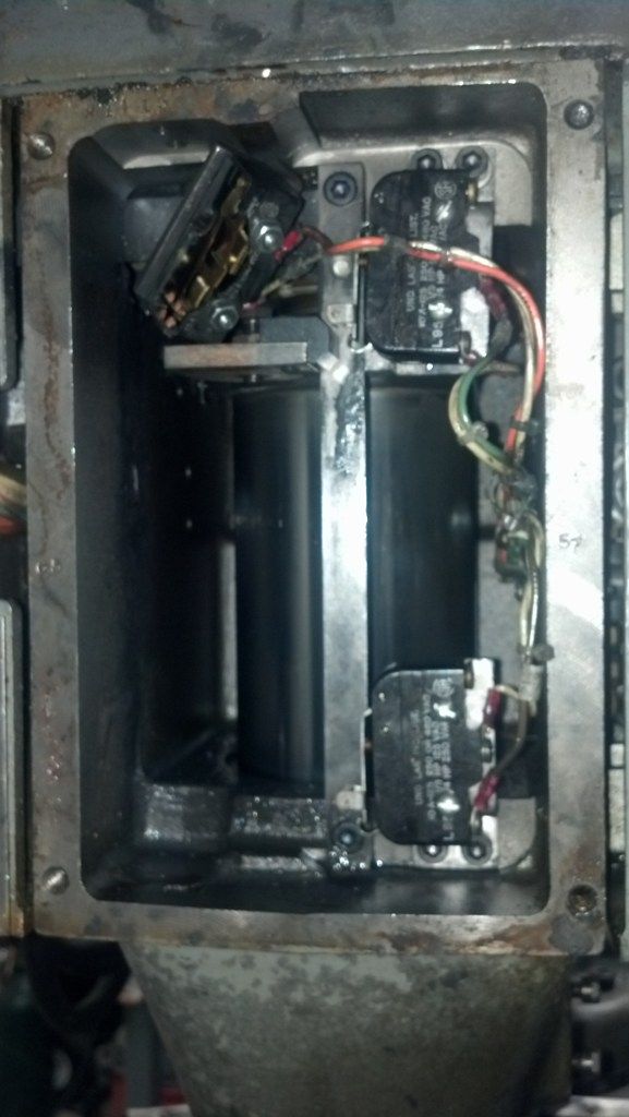
Z limits caused some issues. I was wiring the top switch as the home, middle as upper limit and bottom switch as lower limit. This was all fine and dandy till I screwed up the config for the Z travel and managed to crush the home switch. I forgot the Z has a -5.0in travel and not a positive +5.0in like I programed in the config. I was pissed that I needed to buy a new switch till I researched the switch in the manual and found it be not needed. In the original configuration of the Z switches, the 2 were limits and one was a deacceleration switch before it hit the top switch. With modern controls I dont need one of the switches. In linuxcnc I can set the top switch to home and a limit.
Sunday night I had the table and quill moving by computer. VFD should be on the way after this weekend if CL goes correct.
-
01-07-2014, 06:53 AM #8
Registered
- Join Date
- Aug 2012
- Posts
- 113
That's awesome. I just made a post today about my BP Boss that's coming in next week but this really helps me a lot. I'm gonna send you a PM.
-
01-08-2014, 03:16 AM #9
Moderator
- Join Date
- Nov 2004
- Posts
- 3028
Just a note that the teletype looks like the older style (type 33) that only did 20ma current loop for communication using p1ns 1, 2, 3, 4, 5 on the round amp connector.
For Rs 232, you have to pull the large connector off and let it hang down on the ERS board and use pins 6, 7, an 8 on the amp connector. Baud is set by DIP switches on the ERS. PROCOMM works well. 8 data bits 2 stop bits, no parity, Xon X off enabled. The type 43 teletype did both Rs232 and 20ma current loop.
George(Note: The opinions expressed in this post are my own and are not necessarily those of CNCzone and its management)
-
01-24-2014, 05:07 PM #10
Registered
- Join Date
- Aug 2012
- Posts
- 113
When you ordered your Mesa boards was the 5i25 a standard or low profile?
-
01-24-2014, 06:28 PM #11
Registered
- Join Date
- Oct 2010
- Posts
- 1189
Cool thread i Do a Bridgeport 412 interact retrofit on linuxcnc right now keep up the good work
Gesendet von meinem SM-N9005 mit Tapatalk
-
01-25-2014, 02:57 AM #12
Registered
- Join Date
- Oct 2010
- Posts
- 57
Standard height. Low profile is move for server machines. The total card height is still the same, its just the metal plate on the back. Dont forget to order the din adapter for 5 dollars for the 7i76 Originally Posted by jonesturf
Originally Posted by Tkamsker
I think the tranistors were shot on the board since the RS232 connection was not working. The plan from the start was to retrofit the mill. Originally Posted by machintek
-
01-25-2014, 04:30 AM #13
Registered
- Join Date
- Aug 2012
- Posts
- 113
Thanks for reminding me. I saw them but probably would have forgot when I ordered.
-
02-02-2014, 10:15 PM #14
Registered
- Join Date
- Oct 2010
- Posts
- 57
Long overdue update for the project.
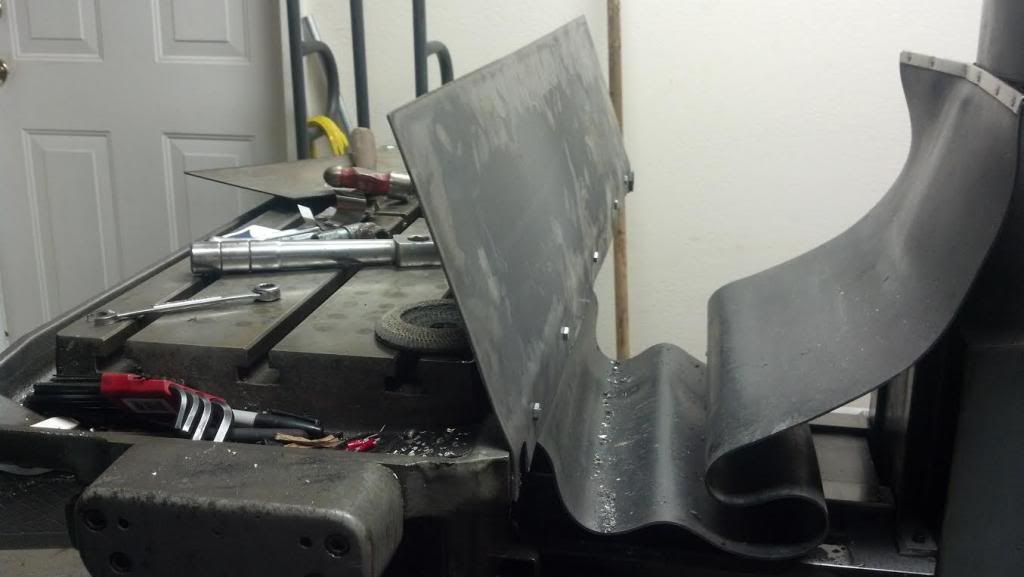
Since I plan to machine with flood coolant I needed to build a enclosure around the table. At this time I don't have a press brake so the second best item was used. After I drilled and taped the table for 1/4-20 holes I was able to mount the rear piece of sheet metal. Little bit of muscle got the piece closer to the 20 degrees I designed.
Side shields tacked into place.
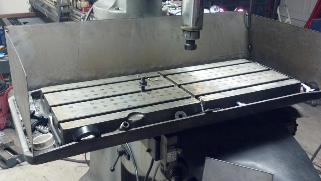
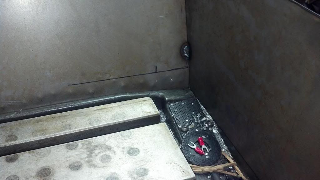
I designed a little shield piece to cover the seam between the table and sheetmetal plus channel the coolant away from the corners of the table.
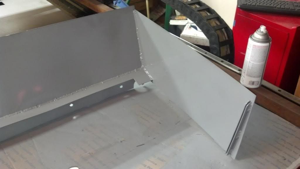
Fixed the coolant tank instead of spending money on a new one. Had to weld up holes in the tank and reinforce the one corner with triangle drops from the plasma table. Still need to rebend the corner of the pump cover.
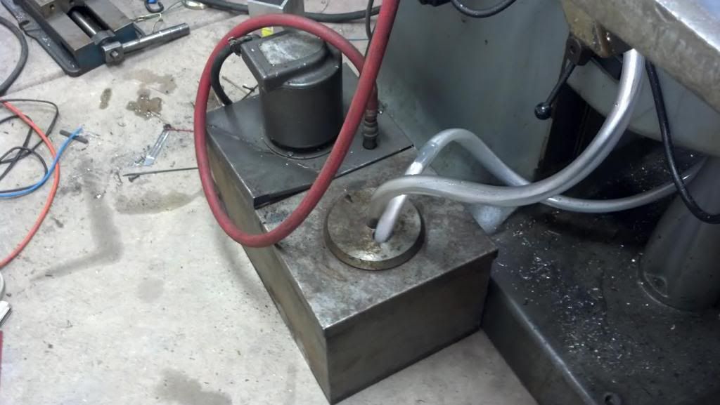
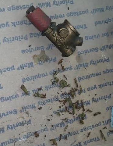
At first the coolant refused to flow thru the coolant nozzle. Found the source of the problem. I had to remove all the plastic from the check valve.
I ran into a few problems during the first test cut.
1. X axis would stop working after 10 mins of running.
2. A lot of noise when running the spindle. Was glad to find out it wasn't coming from the spindle bearings.
3. Vise has mounting issues with mounted inline with the X-axis.
- - - Updated - - -
Problem 1 X-axis turning off
Finally had to mount the drivers down solid and add heat sink compound. I believe this will solve the issue but awaiting a much longer test.
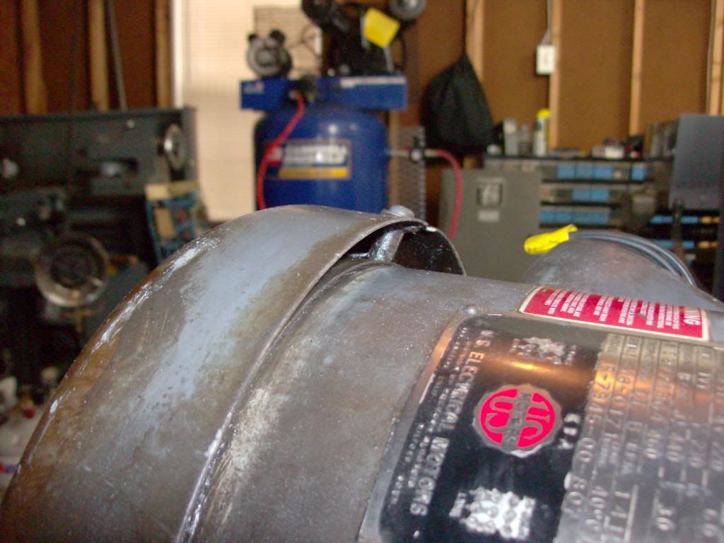
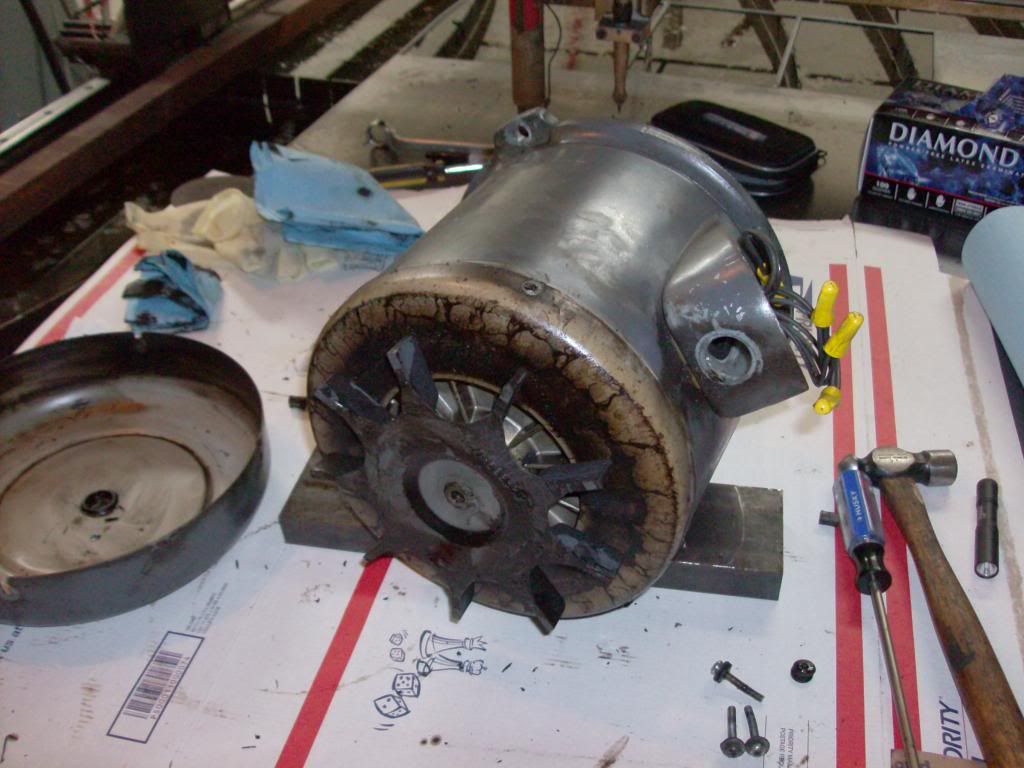
Problem 2 Noise while running spindle
I had some fear that I needed to rebuild the spindle bearings till I torn down the top end for a single pulley conversion instead of the vari-drive system. I found the motor to be making the noise when I spun the shaft. Some how the motor fan shield was bent into the fan.
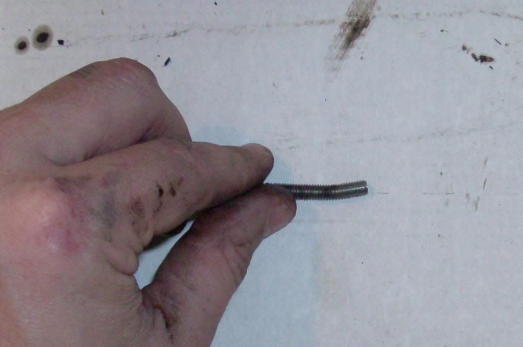
Might as well clean the motor up a bit and slot one of the mounting holes for adjusting belt tension when I use a single groove pulley system.
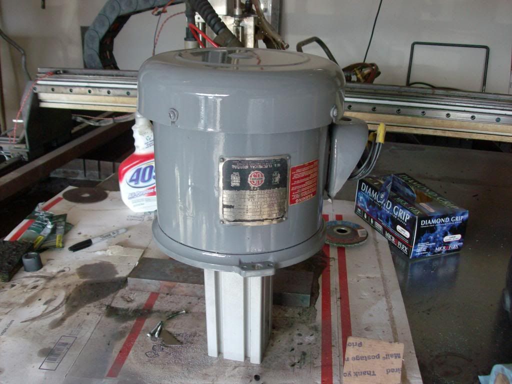
Slotted mounting hole
- - - Updated - - -
Problem 3 Vise mounting.
I will need to modify the coolant shield to allow the vise to mount along the Y-axis. Shouldn't be to hard but I need to cut some additional sheet metal. Somewhat a pain since I don't have a press brake.
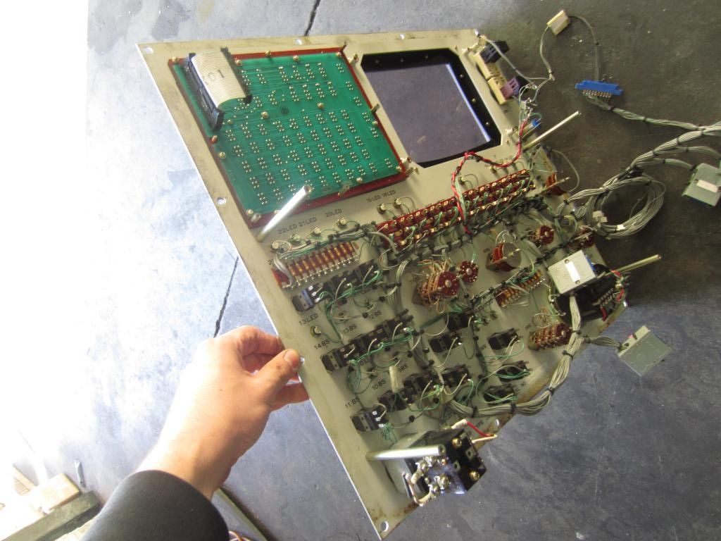
Also picked up another project for the mill once I get some more time. Cheap method for adding a MPG (manual pulse generator) and switches to control the mill. Only ran $160 dollars shipped from ebay. Later on I will design a cabinet that can swing out from the mill. The screen hole size is 8" wide by 6.5" tall. Overall panel size is 21.625" wide by 19.75" tall.
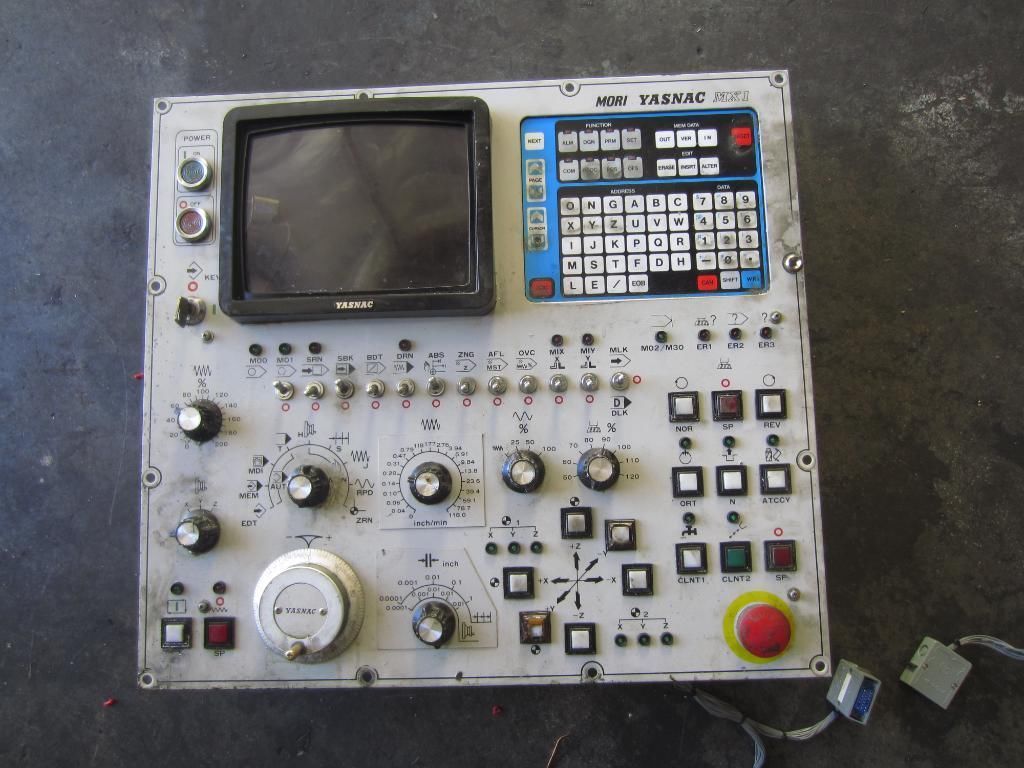
Will be easy to wire into the Mesa 7i76 I/O card. I am debating on ordering another 7i76 I/O card to mount into the cabinet then use serial comm to cut down on wiring. I will need to order a 7i73 pedant/ Control panel card to use the keypad with the setup.
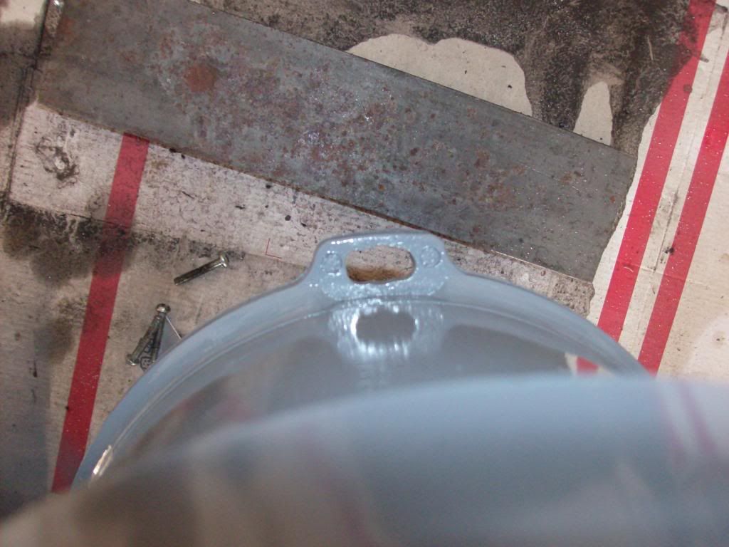
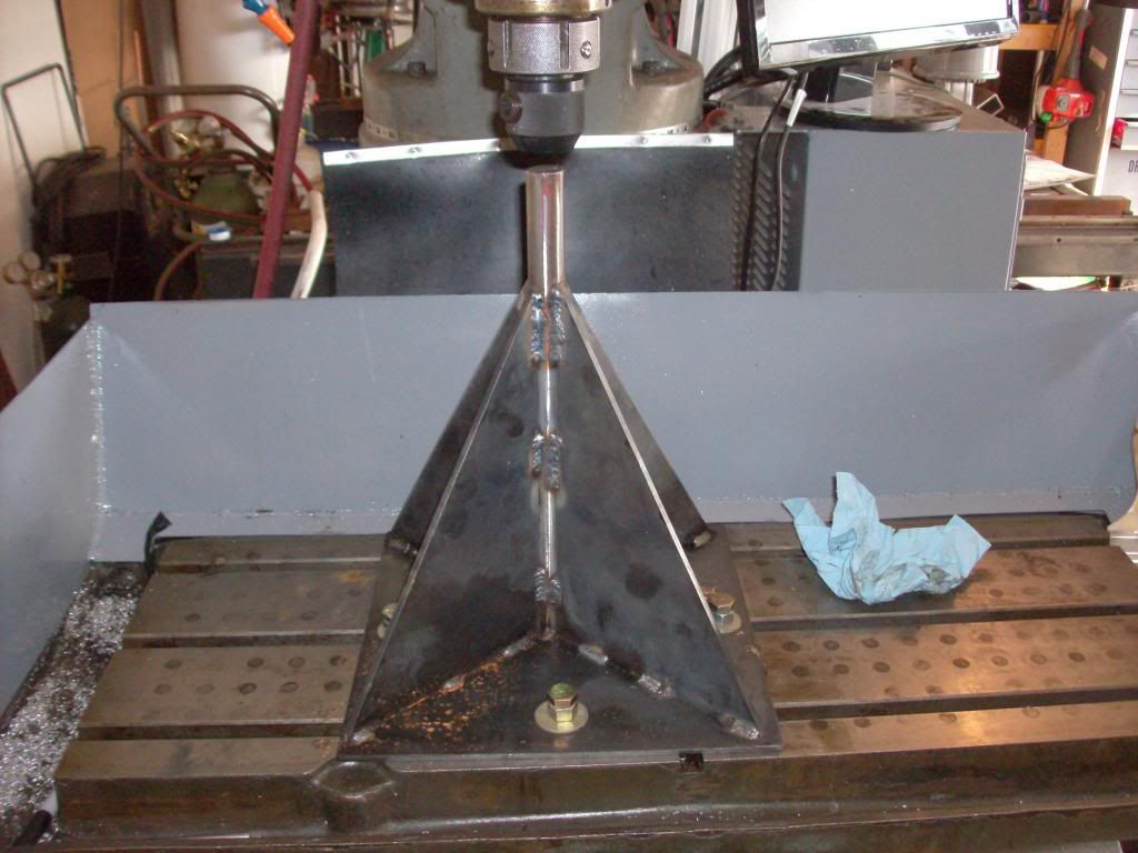
Fixture for moving the spindle assembly. My auction house friend had one of these during the move in of the machine. Not to hard to reproduce with the plasma table from 3/16" sheet metal and a 1 inch rod of steel. I've seen them on the web for 50 dollars I think but cant remember where I saw them. Just tighten rod into a tool holder before unbolting the spindle assembly. Works like a charm and later on I will be painting it.
-
02-03-2014, 04:45 AM #15
Registered
- Join Date
- Oct 2010
- Posts
- 1189
Looks nice but the cabeling Looks like a Lot of work ,..
Gesendet von meinem iPad mit Tapatalk
-
02-03-2014, 05:11 AM #16
Registered
- Join Date
- Aug 2012
- Posts
- 113
That looks great! Just got mine yesterday. Been thinking about what to do to about the coolant mess.
Wondering what kind of speeds you're getting in rapids with the Geckos...if you've had a chance to test them yet.
Sent from my GT-P6210 using Tapatalk
-
02-04-2014, 03:58 AM #17
Registered
- Join Date
- Oct 2010
- Posts
- 57
Just take it one switch at a time. Not sure when I will get around to wiring the panel up. Originally Posted by Tkamsker
Still need to test the full speed of the setup. Maybe this week or next. Decided to paint the upper half of the mill while I wait on the pulley parts. Originally Posted by jonesturf
-
02-04-2014, 04:19 AM #18
Registered
- Join Date
- Aug 2012
- Posts
- 113
That is a cool looking board. Why not use the original Boss panel? Mine has all the jog stuff on it. Was looking at it last night and I like your idea.
Where are you getting the pulley parts?
-
02-06-2014, 12:18 AM #19
Registered
- Join Date
- Oct 2010
- Posts
- 57
Surplus center Originally Posted by jonesturf
1 1-2915-30 30mm METRIC KEYED H-BUSHING 5.50
1 1-2913-137 1.375 KEYED H-BUSHING 5.50
1 1-BKH90 8.75 O.D. H-BUSHING SINGLE GROOVE PULLEY 25.95
1 1-BKH50 4.75 O.D. H-BUSHING SINGLE GROOVE PULLEY 12.95
1 13-AX37 39" AX V-BELT TYPE AX37 NOTCHED 6.40
Cant verify these are correct till friday when I have the mill running on them.
-
03-04-2014, 02:32 AM #20
Registered
- Join Date
- Aug 2013
- Posts
- 12
Any updates to this?


 Reply With Quote


Similar Threads
-
Bridgeport 1 BOSS 6 retrofit
By John Maher in forum Bridgeport / Hardinge MillsReplies: 2Last Post: 12-13-2012, 04:17 PM -
Bridgeport boss 6 retrofit
By dandonegan in forum Gecko DrivesReplies: 3Last Post: 12-18-2011, 05:39 PM -
Bridgeport Boss 6 Possible Retrofit
By rocknrolljunky in forum Bridgeport / Hardinge MillsReplies: 6Last Post: 07-21-2008, 06:54 PM -
Bridgeport boss retrofit
By cat37 in forum Bridgeport / Hardinge MillsReplies: 1Last Post: 08-22-2007, 02:46 AM -
Bridgeport Boss Retrofit help
By moto21 in forum Bridgeport / Hardinge MillsReplies: 7Last Post: 06-10-2005, 04:32 AM
