


The angular contact bearings came in the mail today so I spent the rest of the afternoon and evening getting those installed. Since I was installing the bearings in the original bearing block casting, I went very slowly and was very careful not to screw something up. I did have one close call... I was very near the final OD and decided to press the bearing in and see how it fit. It wasn't real tight, but getting it back out was a wooley booger! I did finally get it out and bored the opening a little bigger so it is a sliding fit with no slop.
I also installed a regular ball bearing on the motor end of the X-axis ball screw. All the feed thrust is on the other end of the table which has dual thrust bearings, so this end just needs to handle the radial force from the belt. Also, in addition to the set screw which holds the extension onto the Y-axis ball screw, I put some Loctite 620 on it and also pinned it with a roll pin.
So, I ordered some connectors like these:
to connect the motors to the cables. I'm currently planning on using 4 conductor , 18 gauge stranded wire for the cables. Is that what most folks use? I'd like to use coiled cable like they used to use on telephone handsets, but have no idea where to find anything like that in the gauge I need. The other end of the cables want DB9 connectors for the Gecko G540.
Chuck
Thread: Rong Fu RF30 Conversion
Results 41 to 60 of 106
Hybrid View
-
11-26-2013, 12:49 AM #1
 Registered
- Join Date
- Dec 2006
- Posts
- 73
-
11-24-2013, 08:06 PM #2
Registered
- Join Date
- Dec 2006
- Posts
- 73
Bob, since I am a complete novice when it comes to CNC, I have absolutely no expectations on speeds attainable. Having said that, I'm sure I am also subject to disappointment once this thing is up and running. I'm open to buying larger motors if push comes to shove, since adapting larger motors shouldn't be too much of a stretch.
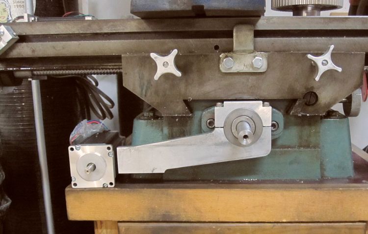
Here's a picture of the Y-Axis motor mount (so far). Still have to make the part that attaches the motor to the arm.
Chuck
-
11-30-2013, 04:09 PM #3
Company Representative

- Join Date
- Aug 2008
- Posts
- 400
For the most part, we use the WeiPu brand connectors and stock spare parts for our machines. We don't advertise or promote our connectors for public sale, however, if someone has a specific need for more information, you can contact [email protected]. We would be more than happy to assist where we can.
Regards,
Novakon Team
-
11-20-2013, 04:08 AM #4
Gold Member
- Join Date
- Feb 2006
- Posts
- 7063
I think you're going to find the single-bolt motor adjustment will move over time, or when you have a "crash"....
Regards,
Ray L.
-
11-20-2013, 11:06 PM #5
Registered
- Join Date
- Dec 2006
- Posts
- 73
So, moving with a "Crash" would be a good thing, right? Keep something else from breaking? As far as moving over time, it's easy enough to reposition and tighten, as long as I don't have to do it every 15 minutes. Originally Posted by SCzEngrgGroup

Chuck
-
11-20-2013, 11:14 PM #6
Gold Member
- Join Date
- Feb 2006
- Posts
- 7063
No, it won't do a thing to jeep anything from breaking in a crash, because the crash will already have occurred by the time it moves. It's just one additional thing that will have to be corrected after the crash. Besides, if it only moves a little, you'll end up with backlash, perhaps a lot, but you won't know it until your parts starts coming out screwed up. Far better to design to deal gracefully with worst-case conditions in the first place..... Originally Posted by cffellows
Regards,
Ray L.
-
11-21-2013, 06:38 AM #7
Registered
- Join Date
- Dec 2006
- Posts
- 73
Hadn't thought about the backlash issue if it only slips a little. Thanks for pointing that out, I'll have to figure out a way to lock it more securely... Originally Posted by SCzEngrgGroup
Chuck
-
11-20-2013, 11:23 PM #8
Gold Member
- Join Date
- Mar 2004
- Posts
- 1806
I look at my timing belt as a "fuse" that will pop if things get to radical (yep, I have popped one) and save the hardware from major breakage. I would much rather break a $3.00 belt than tear up a $100 servo motor or worse!
Art
AKA Country Bubba (Older Than Dirt)
-
11-20-2013, 11:43 PM #9
Gold Member
- Join Date
- Jun 2004
- Posts
- 6618
That is why I asked, because I saw the possibility of swivel on the bracket. Fine if it only occurs intentionally, but not cool if it happens without you knowing about it. Still interested in seeing it completed. I may cnc mine one day if I don't sell it first. It is for sale locally though through word of mouth. Everyone comments, "you mean it's a manual mill with the hand wheels on it? Yes. You ain't gonna get that size cnc mill that has 10 minutes of run time on it for $500.00.
 Lee
Lee
-
11-25-2013, 03:09 AM #10
Registered
- Join Date
- Dec 2006
- Posts
- 73
Here's the Y-Axis motor mount. It will be attached to the mounting arm with two 5/16" bolts through the 1 5/8" long slot. The bolts will be 3/4" apart which will give me 3/4" belt adjustment.
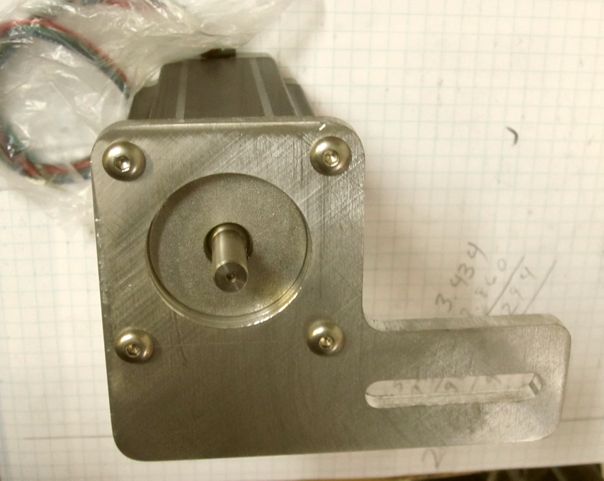
I realize this could still slip, but with two bolts holding it, it should be much more secure.
Chuck
-
11-21-2013, 02:48 PM #11
Registered


- Join Date
- Mar 2007
- Posts
- 304
Thanks for posting your build log, Chuck. Things appear to be moving along nicely.
I am very interested in how you solve the Z-axis issues.
I have a round column mill that I have been contemplating cnc-ing (although I have a bigger mill available - this one might lend itself to adding a tool changer more readily).
The other issue is increasing the Z-travel... It might be worth considering abandoning the round column all together, mounting the Z on a large angle plate, and getting increased z-travel that way......
Please keep posting and keep up the good work.www.CNC-Joe.com
CNC Is Not Just My Passion.. It's My Addiction !!!!
-
11-21-2013, 06:10 PM #12
Registered

- Join Date
- Oct 2008
- Posts
- 2100
One method I have seen pictures of for doing the Z on an RF30/31 is to make an external mount for a ballscrew and nut on the side of the head that raises and lowers a clamp on the end of the quill. The fixed bearing is in the clamp on the quill.
Bob La Londe
http://www.YumaBassMan.com
-
11-22-2013, 01:59 PM #13
Registered
- Join Date
- Mar 2007
- Posts
- 304
hmmm... that would definitely help get rid of the slop in the Z.
If you drive the axis via the fine feed worm/gear mechanism - you could probably use a clamp and two (2) linear guides along the head to take out some of the play in that.
You'd still be limited to the 4"-5" of feed (Which is a major problem with the mill in general, as once you raise/lower the head on the round column - there goes your positional accuracy...., and then I'm back around to the angle plate idea....)
Chuck is doing a great blog here, and hope that he continues. It will be interesting to see how he resolves all the issues with the Z-axis.www.CNC-Joe.com
CNC Is Not Just My Passion.. It's My Addiction !!!!
-
11-22-2013, 04:42 PM #14
Registered
- Join Date
- Oct 2008
- Posts
- 2100
Yes he is. I pointed another RF-30 converter at this thread. Hopefully he will join in or start his own build thread soon. Originally Posted by CNC-Joe
While not an easy solution the classic short cut is to place a round column mill on one side of your shop making sure its bolted down and perfectly level. Then paint a perfectly vertical line on the other side of the shop. You mount a laser pointer on your mill head and point it at the line. When you raise or lower the head you make sure to put the dot on the line. Its not perfect, but its pretty close.
I have an interest in this thread personally as I have an RF-30 also. I was considering converting it until I acquired an old Hurco KMB-1 for less than I paid for the RF-30. I spent 2 1/2 years on the Hurco converting it to PC cotnrol and getting it running right. Now I am considering the RF-30 again.Bob La Londe
http://www.YumaBassMan.com
-
11-29-2013, 04:29 PM #15
Registered
- Join Date
- Feb 2009
- Posts
- 499
Hi Chuck,
I just stumbled onto this thread, and I am anxious to see her cut something fantastic! I have an RF-30 like mill (it actually has the RF name on it) that looks just like yours that I did some mods to (look here if you are curious) and I've often thought about CNCing her. Anyway, good luck on this project, although it looks like luck has nothing to do with it - you seem to have things well in hand."72.6 per cent of all statistics are made up on the spot." - Steven Wright
-
11-29-2013, 05:06 PM #16
Registered
- Join Date
- Dec 2006
- Posts
- 73
Yes, your mill is quite similar to mine. I also built a stand out of wood, although mine has straight sides and built in drawers for storage. I, too, replaced the column clamp bolts as the originals were pretty low quality. I also used large, thick washers to keep the bolt heads and nuts from chewing up the casting, or in my case bondo filler! I drilled and tapped holes through the long vertical key into the column in an attempt keep the mill head in the same vertical position when raised and lowered, but I must have gotten it slightly crooked, because it still moves laterally a bit. My mill has a steel cover around the belts and pulleys that used to rattle when running, so I put a bead of silicon caulk around the edge where the top and bottom meets... fixed that problem. And, I had also added a power feed on the X-Axis. I bought my mill new from Enco in about 1993. The only thing I've ever replaced is the X-axis lead screw nut which finally wore out, partly because I never lubricated it! New one from Enco cost me about $38 with shipping. Originally Posted by revwarguy
I am trying to keep as much of the mill original as I can so that if I ever decide to, I can convert it back to manual with minimal effort.
Chuck
-
11-30-2013, 03:17 AM #17
Registered
- Join Date
- Feb 2009
- Posts
- 499
"The only thing I've ever replaced is the X-axis lead screw nut which finally wore out, partly because I never lubricated it!"
Lubricate it? You're supposed to lubricate it?
"72.6 per cent of all statistics are made up on the spot." - Steven Wright
-
12-10-2013, 02:15 AM #18
Registered
- Join Date
- Dec 2006
- Posts
- 73
Still waiting for the belts and the DB25 cable, so today I finished up the keyways.
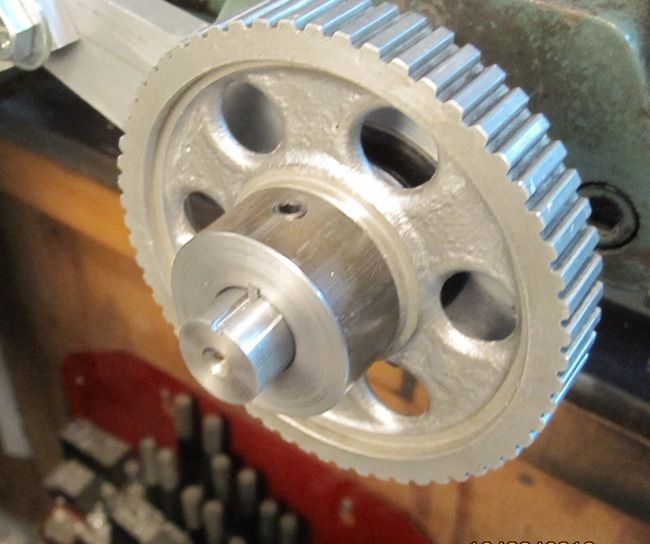
I cut a standard keyway instead of woodruff. That gave me a lot longer key. I used a 3/32" carbide end mill to cut the keyway in the shaft. Easier than I thought it would be. I made the key out of some .093" sheet steel I had on hand.
Hope the cable and belts get her tomorrow. I'm anxious to get this thing working!
Chuck
-
11-22-2013, 05:26 PM #19
Registered
- Join Date
- Oct 2008
- Posts
- 2100
Oh, I meant to ask. Do you think those little steppers are up to the task?
Bob La Londe
http://www.YumaBassMan.com
-
11-23-2013, 06:52 PM #20
Registered
- Join Date
- Dec 2006
- Posts
- 73
Been busy in the shop the past couple of days, but haven't had much to post. I made a new bearing block for the Y-Axis. I tried using a plain bearing race (17mm x 30mm) on either side of the block, but when I put it all back together, it felt spongy. With the Y-Axis clamped slightly, the Y-Axis screw would turn between 5 and 10 degrees before the table moved. I suspect that I could fix that with enough preloading, but decided that angular contact bearings would be a better solution. So, those are on order and should be here by Tuesday.
I made a couple of novice errors while making the new bearing block(s). I assumed the mounting bolt holes were on the same axis as lead screw hole... Well, they were real close, but not quite. Scrap the first attempt at a bearing block. I also assumed the mounting bolt holes would be level and parallel to base of the machine... Again, not so much. The left bolt hole was .050" higher than the right. So, rather than scrap the second bearing block, which is rectangular, I milled an angular swath off the top and matching at the bottom, so now it's a parallelogram! But, since the ball bearing races in that block aren't working as well as I hoped, I'll likely make a third bearing block similar in shape to the original but with the angular contact bearings. Nothing like doing several practice runs before you get to the final product!
Bob, I expect the stepper motors will be beefy enough. I have 20 tooth pulleys on the motors and 48 tooth pulleys on the ball screws. I also have a couple of 60 tooth pulleys I could use if I need them.
Chuck

 Reply With Quote
Similar Threads
-
Rong Fu reverse conversion
By kevrongfu in forum Benchtop MachinesReplies: 6Last Post: 12-13-2013, 12:58 PM -
starting rf30 conversion
By jbors in forum Benchtop MachinesReplies: 0Last Post: 12-08-2013, 05:38 PM -
rong fu 30 mill cnc conversion help
By kiyoukan in forum Uncategorised MetalWorking MachinesReplies: 3Last Post: 02-08-2012, 08:09 AM -
Rong Fu RF 45 CNC Conversion
By JackSmith in forum Knee Vertical MillsReplies: 15Last Post: 02-06-2011, 06:21 PM -
RONG FU RF-31 Conversion Servo or Stepper
By rpcaster in forum Knee Vertical MillsReplies: 2Last Post: 04-26-2007, 03:09 AM
