


I have been using V25 a while now and cannot recall this happening in V23.
I always rough out with ball nosed cutters because the majority of our moulds are small and in this case it's a 4mm ball.
Cutter settings are Depth of Cut 0.3, Step Over 0.5 and allowance 0.3 leaving material for a combination of water line and planar finishing.
The first Z feed move into the block is Z-1.6. Why is it not Z-0.3 as I like to penetrate slowly
I have tried various settings for Rapid Plane, Feed Plane but all result in Z-1.6.
a typical start is,
%
G21
T1 M06
G00 G40 G90 X0. Y0. Z10. S1000 M03 F1010
M08
G00 X-72.73 Y-0.04
G00 Z1.19
G01 Z-1.61
G01 X-72.75 Y-0.04
G01 X-72.71 Y-0.05
any thoughts
Thread: First Z feed move into the part
Results 1 to 20 of 36
-
08-23-2013, 08:29 AM #1
 Registered
- Join Date
- Jul 2009
- Posts
- 82
First Z feed move into the part
V25, Dell T3700 Xeon, 16GB, Nvidia 4000, Win 7 64bit 2 x 22" Dell Monitors.
Moulds completed: 130
-
08-23-2013, 08:41 PM #2
Member
- Join Date
- Sep 2012
- Posts
- 1195
Is the surface relative to the opening below the top of the stock? If so, are there other areas of the part that go to the top of stock? Is this advanced roughing or standard 3d roughing? Is the top of job set for that particular region? I'd have to see a file since I've never had Bobcad do anything like that.
-
08-23-2013, 09:05 PM #3
Registered
- Join Date
- Jul 2009
- Posts
- 82
No, the top surface is what we term the joint line, and Z0 datum for machining. ie take a sphere/square and cut it precisely in 2 at its centre line.
It is standard 3D Z level roughing.
A typical mould would be 2 blocks of aluminium, which can range in physical size depending on the item being moulded. One is termed the top the other the bottom. Into each block is 1/2 the shape of the finished moulded part. Blank rough blocks are either placed in one vice, if small, or 2 identical vices spaced 110mm apart, if large. The blocks are machined in total once mounted ie all surfaces holes and pockets machined in mirror fashion from one to tother including the cavity (the only part I program). The uppermost surface is the mould joint line and hence Z0 for all machining datums. See attached picture.
V25, Dell T3700 Xeon, 16GB, Nvidia 4000, Win 7 64bit 2 x 22" Dell Monitors.
Moulds completed: 130
-
08-23-2013, 09:57 PM #4
Gold Member
- Join Date
- Apr 2009
- Posts
- 3376
Probably can't share a file,eh?Draw something up similar and easy and see if you are still having problems.Like a 1/2 of sphere in a block.Upload if you still having problems.
-
08-23-2013, 10:32 PM #5
Member
- Join Date
- Sep 2012
- Posts
- 1195
I can get the same problem to replicate using a similar parts and set up the way you have it. I'll see if I can figure out what's up.
-
08-23-2013, 11:33 PM #6
Member
- Join Date
- Sep 2012
- Posts
- 1195
Here's a sample file that is similar in style to the molds.
https://files.secureserver.net/0s9MiHxG58NnHB
I think that the issue is related to the fact that it's "Z Level". With Z-level features, regardless of whether it's roughing or finishing, the tool path will not go planar. I think that due to the geometry of the ball end, the motion above the starting point is going towards planar and Z-Level does not really do that. If you run the same part with Advanced Roughing, it roughs all the way to the top without any issue. If you then do a Z-Level finishing pass, you'll notice that the tool does the same thing as the Z-Level roughing and will not go into the sprus or even all the way to the top of the mold. The best way to deal with this type of file will be to use Advanced Roughing, and then follow that up with Equidistant Offset using the boundary of the cavity AND setting the "top of job" to something insignificant relative to your needed tolerances, like -.005mm or even -.001mm to prevent it from going to the top face or into the drilled holes (which I've excluded in the drawing example.
It may be that you don't have the "Pro" level of Mill, and I could feel your pain if you don't. However, if you are doing this kind of work often, it will be the best money you could possibly spend to upgrade to Pro. They are VERY reasonable about this. The additional features in Pro are such that you'll hardly use the standard features any more. It sounds like a cop out, but the tool path as I've seen it is operating the way it should, it just isn't meant to do what you want to do. People doing mold making should be using the Pro version of Mill no matter what. I imagine that if you asked who Pro was made for, it's mold makers or other similar machinists that need exceptional finish quality over complex 3d shapes. I don't think you would be told that about Mill Standard, as it really was made for those who just need basic 3d capabilities and probably spend as much time in 2d as 3d.
-
08-24-2013, 12:52 AM #7
Ghost
- Join Date
- Dec 2008
- Posts
- 4548
The file posted has no toolpath and associated post processor. I'de like to see a file that plunges undefined material.
-
08-24-2013, 12:56 AM #8
Gold Member
- Join Date
- Apr 2009
- Posts
- 3376
No stock either.And what is with this Metric stuff,,lol
-
08-24-2013, 01:03 AM #9
Member
- Join Date
- Sep 2012
- Posts
- 1195
I only posted a model for others to work with. I've played with it, and get the same results as the OP unless I use Pro features that I don't think he has. I thought it would be easier to put the drawing up as a bbcd file than an igs file.
-
08-24-2013, 01:06 AM #10
Member
- Join Date
- Sep 2012
- Posts
- 1195
I'm global like that, it's how I roll. Originally Posted by jrmach


-
08-24-2013, 01:08 AM #11
Gold Member
- Join Date
- Apr 2009
- Posts
- 3376
Need the CAD and CAM if "we" are going to be of help.
Unless the question is ""can you show me how to tool path this with these paths that I have at my disposal"
-
08-24-2013, 01:22 AM #12
Member
- Join Date
- Sep 2012
- Posts
- 1195
Assuming the latter, here's how I would do it with Mill Pro (step over may be more or less depending on desired finish) if I had to use only one tool 4mm ball endmill. My preference would be to use a straight endmill with larger stepovers for the advanced roughing, then maybe rest-rough with the ball end with an allowance, then Equidistant Offset to finish it off. :
https://files.secureserver.net/0sVFoOx27tFamG
-
08-24-2013, 01:30 AM #13
Ghost
- Join Date
- Dec 2008
- Posts
- 4548
Well, what I meant was I created a simple z level rough and posted code that seemed to be ok. You said you reproduced it, so I'de like to see the reproduction of it. The post processor you do it with would be needed too, because that can be playing a role.
-
08-24-2013, 01:31 AM #14
Ghost
- Join Date
- Dec 2008
- Posts
- 4548
I'll be converting the units too. I've been stuck on an island for some time! lol Originally Posted by mmoe
-
08-24-2013, 02:33 AM #15
Member
- Join Date
- Sep 2012
- Posts
- 1195
Burrman,
Are you using a 4mm ball end mill or a straight endmill?
Here's the code that came out using the standard Fanuc OM post, but I get the same results regardless. It goes from 5mm (which I've set as the rapid/clearance height) to Z-2.0996mm, which is a lot more than the .3mm setting I put in there from the top. I'm not seeing it as unusual though, you'd have to start rolling the cutter over the corner of the part, which means that you're machining flat land. Z-Level will not do that, so it seems like it's only calculating the top of the material to remove to be the point where the first valid part surface comes into contact with the radius inside the pocket. The depth would change a little depending on the part geometry, but in my case that is a vertical wall just above a fillet, which means that it will be the full radius of the part. The 2mm radius is why it is 2mm below the surface for the first pass. I think Z-Level rough was just not meant to be used quite that way, where Advanced roughing does the job perfectly.
N04 T01 M06
N05 S7955 M03
N06 G90 G54 X37.0437 Y20.0211
N07 G43 H01 Z5. M08
N08 G01 Z-2.0996 F1212.4502
N09 G17 G03 X35.0997 Y22.1613 I-4.7388 J-2.3514 F2364.2778
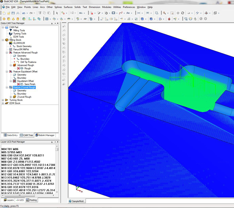
Also, you'll see that a lot of the part that COULD be cut was not, but again I think it's because of the fact that part of the cutter's diameter is over the top of a flatland, so it's not considered a valid surface to run Z-Level off of. At least that's how I think it's interpreting the geometry and where to place toolpaths.
-
08-24-2013, 02:40 AM #16
Member
- Join Date
- Sep 2012
- Posts
- 1195
And here's an image of the Advanced Roughing with the same selected geometry:
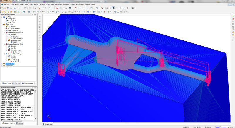
Edit: When I post processed the above Advanced Roughing toolpath, the first Z plunge is to Z-.301mm, so precisely where it should be within tolerances when the step down was set to .3mm. It could have been as deep as Z-.306 and been within tolerance based on the software tolerance settings, so Z-.301 is perfectly within the correct range.
-
08-24-2013, 04:32 AM #17
Ghost
- Join Date
- Dec 2008
- Posts
- 4548
Z level rough. 4 mm with 2mm ball endmill. .3 cut and .3 step with .3 leftover.
Attachment 197438
Attachment 197440
Although, we cant really speak to you about what you have and what you've done because we just have an empty file and you telling us what it's doing for you....
-
08-24-2013, 06:20 AM #18
Registered
- Join Date
- Jul 2009
- Posts
- 82
Thanks for all the replies and yes sorry we moved to metric here in the UK some time back.
I was at home when I had the time to talk about the problem in more depth so could not upload the file.
I do have the V25 Pro version and a second seat on my home comp so created a block with similar cavity and using the same Standard settings get this,
%
G21
T1 M06
G00 G40 G90 X0. Y0. Z10. S1000 M03 F1001
M08
G01 X-29.64 Y-0. Z0.
G01 Y0.36
G01 X-70.35 Y0.36
G01 X-70.35 Y-0.36
G01 X-29.64
G01 Y-0.
G01 X-29.14
G01 Y0.86
G01 X-49.99 Y0.86
G01 X-70.84 Y0.86
G01 X-70.85 Y-0.86
G01 X-29.14
G01 Y-0.
G01 X-28.64
G01 Y1.36
G01 X-49.99 Y1.36
G01 X-71.34 Y1.36
G01 X-71.35 Y-1.36
G01 X-28.64
G01 Y-0.
G01 X-28.14
G01 Y1.86
G01 X-49.99 Y1.86
G01 X-71.84 Y1.86
G01 X-71.85 Y-1.86
G01 X-28.14
G01 Y-0.
G01 X-27.64
G01 Y2.36
G01 X-49.99 Y2.36
G01 X-72.34 Y2.36
G01 X-72.36 Y-2.36
G01 X-27.64
G01 Y-0.
G01 X-27.14
G01 Y2.86
G01 X-49.99 Y2.86
G01 X-72.84 Y2.86
G01 X-72.86 Y-2.86
G01 X-27.14
G01 Y-0.
G01 X-26.64
G01 Y3.36
G01 X-49.99 Y3.36
G01 X-73.33 Y3.36
G01 X-73.36 Y-3.36
G01 X-26.64
G01 Y-0.
G01 X-26.14
G01 Y3.86
G01 X-49.99 Y3.86
G01 X-73.83 Y3.86
G01 X-73.86 Y-3.86
G01 X-26.14
G01 Y-0.
G01 X-25.64
G01 Y4.36
G01 X-49.99 Y4.36
G01 X-74.33 Y4.36
G01 X-74.36 Y-4.36
G01 X-25.64
G01 Y-0.
G01 X-25.14
G01 Y4.4
G01 X-25.11 Y4.86
G01 X-49.99 Y4.86
G01 X-74.8 Y4.86
G01 X-74.83 Y4.82
G01 X-74.86 Y-4.86
G01 X-25.14
G01 Y-0.
G01 X-24.64
G01 Y4.4
G01 X-24.61 Y4.86
G01 X-24.6 Y4.97
G01 X-24.63 Y5.07
G01 X-24.67 Y5.16
G01 X-24.74 Y5.24
G01 X-24.83 Y5.31
G01 X-24.92 Y5.35
G01 X-25.03 Y5.36
G01 X-49.99 Y5.36
G01 X-74.88 Y5.36
G01 X-74.98 Y5.37
G01 X-75.06 Y5.36
G01 X-75.33 Y4.98
G01 X-75.36 Y-4.89
G01 X-75.37 Y-4.97
G01 X-75.36 Y-5.06
G01 X-75.33 Y-5.14
G01 X-75.28 Y-5.22
G01 X-75.22 Y-5.28
G01 X-75.14 Y-5.33
G01 X-75.06 Y-5.36
G01 X-74.97 Y-5.37
G01 X-74.88 Y-5.36
G01 X-25.13
G01 X-25.03 Y-5.37
G01 X-24.94 Y-5.36
G01 X-24.86 Y-5.33
G01 X-24.78 Y-5.28
G01 X-24.72 Y-5.22
G01 X-24.67 Y-5.14
G01 X-24.64 Y-5.06
G01 X-24.63 Y-4.97
G01 X-24.64 Y-4.88
G01 Y-0.
G01 X-24.14
G01 Y4.4
G01 X-24.11 Y4.8
G01 X-24.11 Y5.02
G01 X-24.16 Y5.24
G01 X-24.26 Y5.44
G01 X-24.4 Y5.61
G01 X-24.59 Y5.74
G01 X-24.79 Y5.83
G01 X-25.02 Y5.86
G01 X-49.99 Y5.86
G01 X-74.88 Y5.86
G01 X-74.96 Y5.87
G01 X-75.18 Y5.84
G01 X-75.39 Y5.77
G01 X-75.81 Y5.16
G01 X-75.83 Y5.09
G01 X-75.86 Y-4.89
G01 X-75.87 Y-4.96
G01 X-75.85 Y-5.16
G01 X-75.78 Y-5.35
G01 X-75.67 Y-5.53
G01 X-75.53 Y-5.67
G01 X-75.35 Y-5.78
G01 X-75.16 Y-5.85
G01 X-74.96 Y-5.87
G01 X-74.88 Y-5.86
G01 X-25.13
G01 X-25.05 Y-5.87
G01 X-24.84 Y-5.85
G01 X-24.65 Y-5.78
G01 X-24.47 Y-5.68
G01 X-24.33 Y-5.53
G01 X-24.22 Y-5.36
G01 X-24.15 Y-5.16
G01 X-24.13 Y-4.96
G01 X-24.14 Y-4.88
G01 Y-0.
G01 X-23.64
G01 Y4.4
G01 X-23.61 Y4.73
G01 X-23.61 Y5.08
G01 X-23.69 Y5.41
G01 X-23.84 Y5.72
G01 X-24.07 Y5.98
G01 X-24.35 Y6.18
G01 X-24.67 Y6.31
G01 X-25.01 Y6.36
G01 X-49.99 Y6.36
G01 X-74.88 Y6.36
G01 X-74.95 Y6.37
G01 X-75.22 Y6.35
G01 X-75.49 Y6.27
G01 X-75.73 Y6.14
G01 X-76.27 Y5.37
G01 X-76.33 Y5.16
G01 X-76.36 Y-4.88
G01 X-76.37 Y-4.94
G01 X-76.34 Y-5.26
G01 X-76.24 Y-5.57
G01 X-76.07 Y-5.84
G01 X-75.84 Y-6.07
G01 X-75.57 Y-6.24
G01 X-75.26 Y-6.34
G01 X-74.94 Y-6.37
G01 X-74.88 Y-6.36
G01 X-25.13
G01 X-25.06 Y-6.37
G01 X-24.74 Y-6.34
G01 X-24.44 Y-6.24
G01 X-24.16 Y-6.07
G01 X-23.93 Y-5.84
G01 X-23.77 Y-5.57
G01 X-23.66 Y-5.26
G01 X-23.63 Y-4.94
G01 X-23.64 Y-4.88
G01 Y-0.
G01 X-23.14
G01 Y4.4
G01 X-23.12 Y4.67
G01 X-23.11 Y5.13
G01 X-23.22 Y5.59
G01 X-23.43 Y6.
G01 X-23.73 Y6.35
G01 X-24.11 Y6.62
G01 X-24.54 Y6.8
G01 X-25. Y6.86
G01 X-49.99 Y6.86
G01 X-74.88 Y6.86
G01 X-74.93 Y6.87
G01 X-75.34 Y6.83
G01 X-75.74 Y6.71
G01 X-76.09 Y6.5
G01 X-76.74 Y5.58
G01 X-76.83 Y5.22
G01 X-76.86 Y-4.88
G01 X-76.86 Y-4.93
G01 X-76.83 Y-5.36
G01 X-76.69 Y-5.78
G01 X-76.46 Y-6.15
G01 X-76.15 Y-6.46
G01 X-75.78 Y-6.69
G01 X-75.36 Y-6.83
G01 X-74.93 Y-6.86
G01 X-74.88 Y-6.86
G01 X-25.13
G01 X-25.08 Y-6.87
G01 X-24.64 Y-6.83
G01 X-24.22 Y-6.69
G01 X-23.85 Y-6.46
G01 X-23.54 Y-6.15
G01 X-23.31 Y-5.78
G01 X-23.17 Y-5.36
G01 X-23.14 Y-4.93
G01 X-23.14 Y-4.88
G01 Y-0.
G01 X-22.64
G01 Y4.4
G01 X-22.62 Y4.6
G01 X-22.62 Y5.19
G01 X-22.75 Y5.76
G01 X-23.02 Y6.28
G01 X-23.4 Y6.72
G01 X-23.88 Y7.06
G01 X-24.42 Y7.28
G01 X-25. Y7.36
G01 X-49.99 Y7.36
G01 X-74.88 Y7.36
G01 X-74.92 Y7.36
G01 X-75.47 Y7.32
G01 X-75.99 Y7.14
G01 X-76.46 Y6.85
G01 X-77.2 Y5.79
G01 X-77.33 Y5.28
G01 X-77.36 Y-4.88
G01 X-77.36 Y-4.92
G01 X-77.32 Y-5.47
G01 X-77.14 Y-5.99
G01 X-76.85 Y-6.46
G01 X-76.46 Y-6.85
G01 X-75.99 Y-7.14
G01 X-75.47 Y-7.32
G01 X-74.92 Y-7.36
G01 X-74.88 Y-7.36
G01 X-25.13
G01 X-25.09 Y-7.36
G01 X-24.54 Y-7.32
G01 X-24.01 Y-7.14
G01 X-23.54 Y-6.85
G01 X-23.15 Y-6.46
G01 X-22.86 Y-5.99
G01 X-22.68 Y-5.47
G01 X-22.64 Y-4.92
G01 X-22.64 Y-4.88
G01 Y-0.
G01 X-22.14
G01 Y4.4
G01 X-22.13 Y4.54
G01 X-22.12 Y5.24
G01 X-22.28 Y5.93
G01 X-22.6 Y6.56
G01 X-23.06 Y7.1
G01 X-23.64 Y7.51
G01 X-24.3 Y7.77
G01 X-25. Y7.86
G01 X-49.99 Y7.86
G01 X-74.88 Y7.86
G01 X-74.9 Y7.86
G01 X-75.59 Y7.8
G01 X-76.25 Y7.57
G01 X-76.83 Y7.2
G01 X-77.66 Y6.
G01 X-77.83 Y5.35
G01 X-77.86 Y-4.88
G01 X-77.86 Y-4.9
G01 X-77.8 Y-5.57
G01 X-77.59 Y-6.2
G01 X-77.24 Y-6.77
G01 X-76.77 Y-7.24
G01 X-76.2 Y-7.59
G01 X-75.57 Y-7.8
G01 X-74.9 Y-7.86
G01 X-74.88 Y-7.86
G01 X-25.13
G01 X-25.1 Y-7.86
G01 X-24.44 Y-7.81
G01 X-23.8 Y-7.6
G01 X-23.23 Y-7.25
G01 X-22.76 Y-6.77
G01 X-22.41 Y-6.2
G01 X-22.2 Y-5.57
G01 X-22.14 Y-4.9
G01 X-22.14 Y-4.88
G01 Y-0.
G01 X-21.64
G01 Y4.4
G01 X-21.63 Y4.47
G01 X-21.62 Y5.3
G01 X-21.81 Y6.1
G01 X-22.19 Y6.84
G01 X-22.73 Y7.47
G01 X-23.4 Y7.95
G01 X-24.17 Y8.25
G01 X-24.99 Y8.36
G01 X-49.99 Y8.36
G01 X-74.88 Y8.36
G01 X-74.89 Y8.36
G01 X-75.72 Y8.28
G01 X-76.51 Y8.
G01 X-77.2 Y7.54
G01 X-78.12 Y6.22
G01 X-78.33 Y5.41
G01 X-78.36 Y-4.88
G01 X-78.36 Y-4.89
G01 X-78.29 Y-5.67
G01 X-78.05 Y-6.41
G01 X-77.63 Y-7.08
G01 X-77.08 Y-7.63
G01 X-76.41 Y-8.05
G01 X-75.67 Y-8.29
G01 X-74.89 Y-8.36
G01 X-74.88 Y-8.36
G01 X-25.13
G01 X-25.12 Y-8.36
G01 X-24.34 Y-8.3
G01 X-23.59 Y-8.05
G01 X-22.92 Y-7.64
G01 X-22.37 Y-7.08
G01 X-21.95 Y-6.42
G01 X-21.71 Y-5.67
G01 X-21.64 Y-4.89
G01 X-21.64 Y-4.88
G01 Y-0.
G01 X-21.14
G01 Y4.4
G01 X-21.15 Y5.33
G01 X-21.22 Y5.78
G01 X-21.34 Y6.23
G01 X-21.43 Y6.47
G01 X-21.54 Y6.71
G01 X-21.82 Y7.19
G01 X-21.98 Y7.4
G01 X-22.22 Y7.68
G01 X-22.46 Y7.91
G01 X-22.71 Y8.1
G01 X-22.95 Y8.27
G01 X-23.17 Y8.4
G01 X-23.39 Y8.51
G01 X-23.83 Y8.68
G01 X-24.21 Y8.78
G01 X-24.58 Y8.84
G01 X-24.99 Y8.86
G01 X-49.99 Y8.86
G01 X-49.99
G01 X-74.88 Y8.86
G01 X-75.37 Y8.85
G01 X-75.8 Y8.78
G01 X-76.26 Y8.65
G01 X-76.48 Y8.57
G01 X-76.71 Y8.46
G01 X-77.18 Y8.18
G01 X-77.42 Y8.01
G01 X-77.66 Y7.8
G01 X-77.94 Y7.5
G01 X-78.18 Y7.19
G01 X-78.46 Y6.71
G01 X-78.57 Y6.47
G01 X-78.66 Y6.23
G01 X-78.78 Y5.78
G01 X-78.85 Y5.33
G01 X-78.86 Y3.48
G01 Y-4.88
G01 X-78.85 Y-5.37
G01 X-78.78 Y-5.8
G01 X-78.65 Y-6.26
G01 X-78.57 Y-6.48
G01 X-78.46 Y-6.71
G01 X-78.18 Y-7.18
G01 X-78.01 Y-7.42
G01 X-77.8 Y-7.66
G01 X-77.66 Y-7.8
G01 X-77.42 Y-8.01
G01 X-77.18 Y-8.18
G01 X-76.71 Y-8.46
G01 X-76.48 Y-8.57
G01 X-76.26 Y-8.65
G01 X-75.8 Y-8.78
G01 X-75.37 Y-8.85
G01 X-74.88 Y-8.86
G01 X-25.13
G01 X-24.58 Y-8.84
G01 X-24.21 Y-8.78
G01 X-23.83 Y-8.68
G01 X-23.44 Y-8.53
G01 X-23.05 Y-8.33
G01 X-22.83 Y-8.2
G01 X-22.62 Y-8.04
G01 X-22.41 Y-7.86
G01 X-22.2 Y-7.66
G01 X-21.98 Y-7.4
G01 X-21.69 Y-6.99
G01 X-21.48 Y-6.57
G01 X-21.33 Y-6.19
G01 X-21.22 Y-5.8
G01 X-21.15 Y-5.37
G01 X-21.14 Y-4.88
G01 Y-0.
G00 Z3.3
G00 X-50.03 Y0.45
G00 Z3.
G01 Z-0.3 F50
F1000
G01 X-70.44 Y0.45
As you see it runs a complete sequence at Z0 before the first real cuts at Z-0.3. I cannot explain why this did not do the same at work which I tried 2 or 3 times.
Now I have just loaded up V23 and run the same part and it did the very same thing....no cut until running a complete sequence at Z0. A bit of head scratching and I found that I had to specify the Top of Job as the first cut plane i.e. in this case -0.3. Now that works.
%
G21
T1 M06
G00 G40 G90 X0. Y0. Z10. M03 S1000
X-50. Y0.45
M08
Z3.
Z3.3
G01 Z-0.3 F50
X-70.45 Y0.45
Y-0.45
So I think in the transition form V23 to V25 I had forgotten to apply this setting.....silly me.
Thanks for all your inputs and probably the wasting of time.V25, Dell T3700 Xeon, 16GB, Nvidia 4000, Win 7 64bit 2 x 22" Dell Monitors.
Moulds completed: 130
-
08-24-2013, 06:27 AM #19
Gold Member
- Join Date
- Apr 2009
- Posts
- 3376
18 posts on this,and no .bbcd file with tool paths to look at.
-
08-24-2013, 06:27 AM #20
Member
- Join Date
- Sep 2012
- Posts
- 1195
I think I've nailed down what's going on for myself and the OP. I think it is a bit of a glitch in Z-Level Roughing, but a predictable one. I only call it a glitch because it should still recognize that material needs to be removed relative to the top of the part, not a position within the part. It doesn't if done the way I and most likely the OP set it up. If I run the Z-Level Rough feature on the part, and use the pocket perimeter as a boundary, then select "Inner Most Only" (a habit I have for doing pockets), I get a tool path that starts as I've shown, about 2mm below the surface. If I select "All" instead of "Inner Most Only", I get tool paths all the way up and throughout the sprus as BurrMan shows (also using the pocket edges as a boundary, or you cut the sidewalls, etc). That is the setting that is causing the tool path to start too low, but if you think about it, shouldn't is still start cutting where relative to the height of the material/part? That's where I think it's a bit of a glitch. I also would say that it wasn't meant to be used that way perhaps, so hard to fault it for behaving that way.
A little more testing starts to reveal the nature of what is happening in terms of how it determines the depth of the first pass. After making a part with no sprus intersecting the edge (so basically a perfectly isolated pocket), I get the tool path all the way to the top surface (or just below by the .3mm). Once you add a spru of any size, the new "top" used to start machine step downs is the LOWEST plane that intersects the pocket, which is the bottom of the spru cavity. If there is an intersecting surface below zero that eventually connects with the side wall of the part below zero, that is the surface that will be referenced as the top of the pocket for the purpose of tool path generation, even if it's surrounded by much taller surfaces, and that is the plane that the first cut will be determined by, not the plane of the highest intersecting entity.
There does seem to be a tolerance associated with this issue though, sort of like a gap tolerance. Assuming that I use the same setting in both cases, and that I have checked "Inner Most Only", if I suppress the smaller individual spru, and keep the "Y" shaped spru, the bottom of the spru becomes the maximum height of the toolpath. However, if I suppress the "Y" spru and keep the spru that narrows to about .5mm tall, the toolpath actually starts above that level as if it were an isolated pocket. By suppress, I mean that I uncheck the feature in CAD in a similar fashion to using "Do Not Post" in Bobcad and export the IGES without that CAD feature for those who may not know.
Using a boundary and selecting "All" instead of "Inner Most Only" apparently must be done every time if you have sprus.
")

 Reply With Quote
Similar Threads
-
adjusting feed plane to allow rapid move
By bobcad guy in forum BobCad-CamReplies: 29Last Post: 05-13-2013, 02:06 PM -
Move part after layout?
By elafing1 in forum Uncategorised CAD DiscussionReplies: 1Last Post: 07-19-2012, 11:27 PM -
Axis move during feed hold
By 1ctoolfool in forum Haas MillsReplies: 3Last Post: 09-12-2006, 04:12 PM -
Move part origin
By vertcnc in forum SolidworksReplies: 1Last Post: 11-06-2005, 09:15 PM -
Move part
By Thungvilai in forum GibbsCAMReplies: 1Last Post: 10-23-2003, 06:09 AM
