


Hi,
I thought I would share my build.
It's probably a little late in the process to start a build thread, I think it's about 80% there, but thought I would share anyhow.
I started this project around 1 year ago after a number of previously stalled projects (bought components, etc and then sold them off again).
My aim is to machine Aluminium and some plastic. No steel. Only intended as a hobby machine, not production.
Originally I wanted to make this a scratch build, but became daunted with the task of building the X,Y axis.
After looking at lots of stand alone X,Y tables and not liking the price or travel I eventually found a second hand mill base.
I believe that this is from an RF45 clone, this one would have had a round column Z axis.
I have ended up fabricating my own Z axis to suit.
Because of the delays is deciding what to do with the X,Y axis I ended up building the complete electronics before having any hardware done.
Some Pics to start with.
Attachment 203310
Attachment 203312
Thread: RF-45 Hybrid Scratch Build
Results 1 to 20 of 101
-
10-04-2013, 01:00 AM #1
 Registered
- Join Date
- Sep 2013
- Posts
- 88
RF-45 Hybrid Scratch Build
-
10-04-2013, 02:56 AM #2
Registered
- Join Date
- Sep 2013
- Posts
- 88
More photo's coming soon, Including the Z axis mounted up.
For some reason the pics I took last night are not on my phone anymore.....
Some specs:
Travels: Y = 350mm, X= 200mm, Z=300mm
Axis: 4 (rotary axis coming soon)
Spindle: ER20 DIY (not finished)
Spindle Motor: 1Hp 4P 3 phase
Spindle Drive: Single phase input VSD (Mach 3 Control via customer PWM converter)
Ballscrews: Chinese rolled 1605 type (X,Y) Japanese unknown type (Z)
Stepper Drives: Own design \ construction (4A)
Break-out Board: Chinese 5 Axis Parallel port type (a not so cheap one after misadventures with bad quality copies)
Steppers: NEMA 23 425 Oz-in
Coolant: DIY Fogbuster copy
-
10-04-2013, 11:35 PM #3
Registered
- Join Date
- Sep 2013
- Posts
- 88
With unfinished z axis
Sent from my GT-I9100T using Tapatalk 4
-
10-04-2013, 11:45 PM #4
Registered
- Join Date
- Sep 2013
- Posts
- 88
DIY fogbuster copy based on the patent docs. As yet un tested
Sent from my GT-I9100T using Tapatalk 4
-
10-04-2013, 11:46 PM #5
Registered
- Join Date
- Nov 2007
- Posts
- 980
Absolutely love the rack system, and is that a piece of a Taig Mill Z axis square tubing on your Z assembly?
DaveDave->..
-
10-05-2013, 12:40 AM #6
Registered
- Join Date
- Oct 2005
- Posts
- 328
Do post some info on your spindle. I remember seeing a thread somewhere about turning one of those straight-shank ER collet holders into a spindle. Haven't looked at it in a long time. I want to do something like that for the mill I'm building. What did you start with and did you have any difficulties because of the hardening?
Dave
-
10-05-2013, 08:55 AM #7
Registered
- Join Date
- Sep 2013
- Posts
- 88
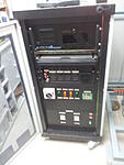
The rack system seemed like a good idea. I picked up the cabinet for $50. Problem is that rack accessories like blanking panels are massively over priced. Originally Posted by fretsman

Overall the result is neat, and will be better when I replace the labels with ones I engrave on the machine.
It does seem like most others on th forum are trying to build very small enclosures, while mine is as big as the machine. ...
Thr column is home made from an I beam and heavy plate. The screw and inner bearing rail assembly is from some sort of optical equipment which I bought online. I added outboard supported rails to increase rigidity. A 300N gas strut takes load off the screw.
Sent from my GT-I9100T using Tapatalk 4
-
10-05-2013, 08:59 AM #8
Registered
- Join Date
- Sep 2013
- Posts
- 88
I'm planning to build the spindle from a straight ER adaptor. Originally Posted by whateg01
Did try to tap the top end, but its way way too hard.
Instead I have brazed in some fine threaded rod which will have a keyway cut in it.
Hope this works.....
Will post some pics and details soon.
Sent from my GT-I9100T using Tapatalk 4
-
10-05-2013, 10:54 PM #9
Registered
- Join Date
- Oct 2005
- Posts
- 328
You are right on that account. I always joke when we are building a system at work that I am in the wrong business. OTOH, may I point out that, once you are done building this mill, you will have at your disposal a mill capable of machining your own panels. Originally Posted by migrusch
Dave
-
10-05-2013, 10:56 PM #10
Registered
- Join Date
- Oct 2005
- Posts
- 328
That's what I was afraid of. Do you worry that the heat from the brazing affected the dimensions of the part? I guess I'll have to search for the thread I saw where somebody else had done this. It seems like they had said that the shank was only case hardened, so maybe grinding through that will get me to something that can be threaded and keyed. Originally Posted by migrusch
Good luck; I hope it works for you! (So that I can copy!)
Dave
-
10-06-2013, 07:52 AM #11
Registered
- Join Date
- Sep 2013
- Posts
- 88
The irony is killing me. Spent ages drilling and filing holes in the panels thinking the whole time how neat and easy it would be if I already had a CNC.... Originally Posted by whateg01
Sent from my GT-I9100T using Tapatalk 4
-
10-06-2013, 07:58 AM #12
Registered
- Join Date
- Sep 2013
- Posts
- 88
I don't think the heat will have affected anything dimensional. .. but will re check. Originally Posted by whateg01
To be honest the body of the spindle is my main concern at this stage.
The backup plan is to buy a ready built ER20 spindle/motor unit. The problem bis that this also requires a new high frequency vfd... I'll post a link to the product soon.
Sent from my GT-I9100T using Tapatalk 4
-
10-08-2013, 01:07 AM #13
Registered
- Join Date
- Apr 2013
- Posts
- 97
You're doing a beautiful job can't wait to see some cuts
-
10-09-2013, 12:31 AM #14
Registered
- Join Date
- Sep 2013
- Posts
- 88
Last night I decided to try and check the alignment of the Z axis.
To this point I have just chucked the tower on and and lightly torqued it down to the base.
Obviously I need to fully tram the system once the spindle is mounted up. At this stage I just want to check that the Z way is perpendicular to the table.
I started off playing with a cross hair laser. The idea was to move the axis up and down and measure the movement of the centre point.
At first I attached the laser to the Z axis arm. It was hard to clamp in place accurately, and the movement up and down was causing the lens to move about.
The other issue is that this would have only worked if I could guarantee the laser was aligned perpendicular to the table. I could have been seeing error in the laser mounting rather than the axis.
The next step was to mount the laser on the table and project onto the arm.
At this point I started to question what I was doing. The laser looks great and certainly gives an impression of Hi Tech accuracy, but I have do idea how aligned the beam is to the body and the loose thread between the lens and body made me suspicious.
Time for a new strategy......
Attachment 203882
Attachment 203884
-
10-09-2013, 12:33 AM #15
Registered
- Join Date
- Sep 2013
- Posts
- 88
My next attempt to align the Z axis used a large square (of unknown accuracy) against the arm. Then checking the variation in gap over the full travel.
Before doing any shimming etc, there seems to be arpox 1mm over 300mm. No too bad given the way the axis was fabricated.
So now a question to the forum..... Any ideas on how to better (more cleverly) do this alignment ?
I don't have access to any large angle plates etc.
I hope there is a clever empirical way to do this without buying something that I won't likely need again......
Attachment 203886
-
10-09-2013, 01:56 AM #16
Registered
- Join Date
- Apr 2013
- Posts
- 97
You're doing a great job I don't want to sound like some of the people who posted in my build . But I think this is the time to check for flex. Because if you have to do any modifications for strength squaring it now be wasted. Place a dial indicator approximately where spindle would be located. High enough up the Z to where you think you tallest parts with vice would be. Put the dial indicator up against something solid on the table does not have to be square. With a hefty push side to side and back and forth you need have .002 thousands or hopefully less. Give it a good hit the Palm of your hand You don't want to seem springy in any direction
-
10-09-2013, 02:43 AM #17
Registered
- Join Date
- Sep 2013
- Posts
- 88
Dick, Originally Posted by dick cnc
Thanks for your response.
I assume you mean 2 thou (or 0.002 inches) ? Certainly 2 thousandths of a thou would be great.....
I did make this measurement earlier in the build (like last week) and was up around 12 thou, but I hadn't torqued everything up, the spring washers on the column by body were not compressed for example and the Front rail bearing wasn't attached.
I will tighten everything up and measure again. As you point out, I don't want to have to make modifications later.
Out of interest what value did you achieve?
-
10-09-2013, 03:01 AM #18
Registered
- Join Date
- Apr 2013
- Posts
- 97
Front to back .001 side to side .002 these are measured in one direction. In the other direction the same in other words overall push pull on front to back.002 and side to side .004
-
10-09-2013, 12:08 PM #19
Registered
- Join Date
- Sep 2013
- Posts
- 88
Best I can get is .004 vertical and .004 side. For aft is so tight I can barely get 0.0005. Originally Posted by dick cnc
Surprised given our machines have similar travel and the construction of mine is much heavier.
Most of my movement seems to be in the bearings and not arm or tower.
I still have a few minor upgrades to do, but this would only improve by one thou....
Sent from my GT-I9100T using Tapatalk 4
-
10-09-2013, 02:43 PM #20
Registered
- Join Date
- Apr 2013
- Posts
- 97
I can't really see the bearing set up in your pictures for the z but looks like you've got a round supported linear rail in the front. I have built plenty machines using these in my life routers and all sorts of production machinery and slides. They work okay with force applied down on the rail but tend to spring open laterally. Can you show us a little more on the bearing set up or the Z. I think you're probably going to be okay if you use higher RPM spindle

 Reply With Quote
Similar Threads
-
Scratch build First Machine
By Alchemist29 in forum CNC Wood Router Project LogReplies: 4Last Post: 03-13-2013, 05:47 PM -
CNC lathe scratch build!
By aarongough in forum Vertical Mill, Lathe Project LogReplies: 37Last Post: 02-07-2013, 10:06 PM -
First build from scratch
By Sockles in forum DIY CNC Router Table MachinesReplies: 7Last Post: 08-23-2011, 11:29 PM -
Joe's 4x4 hybrid build/2006 build
By krap101 in forum DIY CNC Router Table MachinesReplies: 1Last Post: 08-09-2010, 11:30 AM
