


Just finished:
Arduino UNO
Wagner
Thread: CNC Indexer (Arduino based)
Results 1 to 20 of 54
Hybrid View
-
06-30-2013, 11:26 PM #1
 Registered
- Join Date
- Jun 2013
- Posts
- 24
CNC Indexer (Arduino based)
-
07-01-2013, 03:23 PM #2
Member
- Join Date
- Aug 2005
- Posts
- 158
Looks great.
Will the details of the hardware and software be available or is this a proprietary item?
-
07-01-2013, 04:02 PM #3
Registered
- Join Date
- Jun 2013
- Posts
- 24
Hi arvidj,
Thank you.
Details to come (hardware and software). I'm working on the diagram, and pictures.
Wagner
-
07-01-2013, 06:17 PM #4
Registered
- Join Date
- Jun 2013
- Posts
- 24
Diagram:
Attachment 190476
Wagner
-
07-01-2013, 09:02 PM #5
Registered
- Join Date
- Jan 2008
- Posts
- 52
Looking really good and looking forward to the source sketch.
-
07-03-2013, 01:54 PM #6
Registered
- Join Date
- Jun 2013
- Posts
- 24
Good morning to all,
For this project I've only used the Arduino environment.
The folder "Indexer" must be copied to your sketch folder and the lib folders "Wlcd and Wstepper" to your sketch\libraries folder.
After that, just use the Verify or, if you have the Uno connected, the Upload buttons.
In my instalation:
\Arduino
........\Wagner
..............\Indexer
.................Indexer.ino
..............\libraries
..................\Wlcd
......................Wlcd.h
......................Wlcd.cpp
..................\Wstepper
......................Wstepper.h
......................Wstepper.cpp
Anyway, this morning I've figured out where to find the generated hex file, and here it is:
-
07-12-2013, 04:38 AM #7
Registered
- Join Date
- Jan 2008
- Posts
- 52
Finally.. I just received the lcd sheild. No motor connected yet but that will happen tomorrow. I set the configuration to suit my system.
The code built fine (with Arduino 1.0.5) , but I seem to have a problems with both Jog and Continuous modes.
In Jog the up/down keys do not adjust the Jog degrees; the left/right seem attempt operation, but of course it was at zero jog so no increment of displays.
In Continuous the left or right keys start operation, but there is no way to stop other than pressing the reset switch on the lcd shield.
I did see on the schematic that you use D11/D12 for Continuous mode. Is there anything I need to do on the lcd to enable these for the Duo?
Before I dig into the sketch, can you please verify the code you uploaded is what you intended? And.. have I missed something in operation?
BTW... one small modification I'll need to make - the reduction gear parameter expects an integer... before any pulley or other gearing, mine is 1: 26.8512 due to the planetary gearbox.
-
07-12-2013, 05:42 AM #8
Registered
- Join Date
- Jan 2008
- Posts
- 52
OK.. an update. I uploaded the hex file you posted and JOG started working fine because of the default value of 000.001, but Continuous mode still can't be interrupted except with a hard reset.
BUT there is a bug with JOG that may have been the root cause of my initial report of Jog not working. - step down the jog increment below 000.001 (i.e. 000.000) it will not wrap to 100.000 and you can not step it back up again from zero.. Once at 000.000 jog appears not to work. Easy fix.
in f41()
case KDW:
Cnf.dJog/=10;
if(Cnf.dJog<=0) // was originally if(Cnf.dJog<0)
Cnf.dJog=100000;
A suggestion.. add a version number to your initial display to help discussion and bug tracking.
-
08-20-2013, 09:12 PM #9
Registered
- Join Date
- Jun 2013
- Posts
- 24
Hi rooies13,
No, the way it is it will not work.
For that you will probably need a full cnc mill, with a 4th axis.
The mechanical part of this project would work as the 4th axis; but not the Arduino/electronics part.
Wagner
-
07-01-2013, 09:21 PM #10
Registered
- Join Date
- Jun 2013
- Posts
- 24
A little bit about the mechanics:
Tank you lakeside53. The code is at home. Please wait til tomorrow
Wagner
-
07-02-2013, 01:57 PM #11
Registered
- Join Date
- Jun 2013
- Posts
- 24
Here is the software:
Indexer.zip
\Indexer\Indexer.ino.........The main code
\Libraries\Wlcd................Modified version of LCD4Bit
\Libraries\Wstepper..........My striped down version of AccelStepper
Wlcd is a modified version of LCD4Bit; includes code for activating cursor, create custom characters and digital read keys.
Wstepper is a rewrite, stripped down version of AccelStepper. Contains the minimum to control the stepper motor with acceleration and deceleration.
My thanks to the people who created the original libraries.
Wagner
-
10-22-2022, 09:41 PM #12
Member
- Join Date
- Jul 2012
- Posts
- 2
Re: CNC Indexer (Arduino based)
Hello, is it possible to receive Wstepper and Wlcd, i cant find them anymore.
-
07-02-2013, 02:29 PM #13
Registered
- Join Date
- Jun 2013
- Posts
- 24
First thing when running the code, you must set the configuration.
Steps/Rev: 200.........Stepper motor, number of steps per revolution
MicroStep: 8............Stepper controller, number of micro steps
Reductn: 72.............Total gear train reduction
MxVl(°/M): 1200........Maximum velocity in degrees per minute
Acc(°/s²): 20...........Acceleration in degrees per second per second
Bcklsh(°): 0..............Backlash compensation in degrees
Wagner
-
07-12-2013, 01:43 PM #14
Registered
- Join Date
- Jun 2013
- Posts
- 24
Hi lakeside53,
Yes, you have found a bug. The code should be (Cnf.dJog<=0); thank you.
The Continuous mode needs the digital inputs D11 and D12 connected (hardwired) on the keypad. See the diagram on post #4 and the picture:
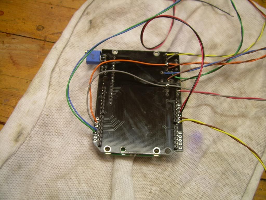
The Gray and Orange wires connects the keys to digital inputs.
And the reason is that during continuous mode, the code must check if the key is still pressed, and at the same time generate pulses for the motor at maximum speed. The original way to read the keys on the LCD is analogRead() on pin A0 (all the keys are connected here, via divider resistors); But analogRead is very slow; if used in this case, the motor would not reach max speed.
So I've decided to connect the left and right keys to digital inputs and use digitalRead() on continuous mode. digitalRead is almost instantaneous.
If you don't want to connect the wires on your shield, change the line of code #1188 as follows:
if(mod<3)
while(stp.Run());
else
{
while(lcd.getkey()) // was while(lcd.digkey())
stp.Run();
stp.Stop();
while(stp.Run());
}
stpgon=stp.Gone();
I will think about the issue of the reduction rate, and get back to you later.
Wagner
-
07-13-2013, 01:48 AM #15
Registered
- Join Date
- Jan 2008
- Posts
- 52
I wired the shield like your picture and it works fine in continuous mode. The key switches are connected to D5 and D6 though... not D11, 12. The code (KD0 and KD1) does explicitly reference 11 and 12, so I'm not sure what's going on. Maybe there's some mapping I'm not aware of?
New problem. I'm not exactly sure what is going on but these will reproduce the bug each time :
1) Select Degree mode. Enter 180.000 degrees as the increment. Press the LEFT key for 3 cycles - display will read P:-3x180.000 ; now press the RIGHT key once. The stepper will now drive infinitely and you can't get out unless you press the Reset button.
2) Select Degree mode. Enter 180.0000. Press the Right key for 4 cycles.. All works as expected; the fifth and ongoing cycles will move 360 degrees instead of 180.
If you select say 45 or 90, instead of 180, the same thing happens but at proportionally higher cycle counts - something to do with the total number of degrees or steps.
Similar things happen in Jog mode. Easier to see when the degree increment is high, like 100.
BTW.. for those building this -the lcd shield (the same part number) I received is slightly different to the above picture - there are more pins so be careful just following the pictures.
-
11-19-2013, 10:15 PM #16
Registered
- Join Date
- Nov 2013
- Posts
- 7
Hi Wagner -- First of all great work and thanks for sharing your project!
I have been working on something related, and a member of a local group just posted a link to your project, so this is the first I've seen it.
I am using an Arduino, the same Keling stepper motors, and the accelstepper library too.
I am curious why you decided to modify/create your own version of the accelstepper library? Was there something you couldn't do with it, or some other reason?
--Jon
-
07-02-2013, 03:29 PM #17
Registered
- Join Date
- Jun 2013
- Posts
- 24
Screens:
Wagner
-
07-02-2013, 05:04 PM #18
Registered
- Join Date
- Jan 2008
- Posts
- 52
Thanks. I'll try to build it in the next couple of days. It looks straight forward but it always does when someone else does all the hard work!
Are you using WINAVR? What version?
-
07-13-2013, 02:42 PM #19
Registered
- Join Date
- Jun 2013
- Posts
- 24
Solved.
Attached, the new version.
Or, if you want to change the code yourself,
Function "void Index(int mod,int..." about line 1165
if(mod<3)
{
newdeg%=360000L; // was 3600000L (too many zeros...)
newpos=lround((float)newdeg/360000.0*(float)stprot);
}
Now, about the digital input pins, on the LCD shield, connector J5, the order of the pins are: D0 D1 D2 D3 D11 D12 D13
I was confused at first too. But checking whit a ohmmeter confirmed what is shown on the pdf diagram provided by SainSmart (LCDKeypad Shield SCH.pdf)
Wagner
-
07-13-2013, 04:42 PM #20
Registered
- Join Date
- Jan 2008
- Posts
- 52
Yes that worked! Funny thing... Very late last night I decided that "tomorrow" was going to go though that exact piece of code to figure what was happening, but extra zeros are sneaky and hard to spot

And you are correct on J5. For some reason I thought they were just mapping the adjacent Uno pins .
The current LCD board shipped from Sainsmart (China) : My J5 as 9 pins - the right most pin is now VCC. I also have 10 more header pins on the bottom right - two rows above A0->A5 designated +5 and GND. The lcd contrast potentiometer now points to the viewer so you can insert a small screwdriver though the front panel to adjust.
I'll keep testing, but the obvious bugs are now gone.
I'm going to try another driver board and do some comparative testing. On the same rotary table the Toshiba chip board just doesn't seem to perform like my Gecko G251v in micro-step mode (I was driving it from grbl on an Uno), and has much more "vibration" when driving (Gecko has an adjustment for this). Of course, the Gecko is nearly 6X more expensive!

 Reply With Quote
Similar Threads
-
Arduino Modbus?
By wbrandsmeier in forum Mach Software (ArtSoft software)Replies: 1Last Post: 02-01-2014, 07:47 PM -
Arduino + tb6560 + cd rom cnc machine help
By joetemus in forum Community Club HouseReplies: 5Last Post: 11-28-2013, 04:56 AM -
EMC with Arduino for USB I/O?
By sansbury in forum LinuxCNC (formerly EMC2)Replies: 23Last Post: 05-05-2012, 09:27 PM -
Interfacing an Arduino-based pendant
By sansbury in forum Mach Software (ArtSoft software)Replies: 4Last Post: 12-07-2011, 04:40 PM -
Arduino
By LTP in forum CNC Machine Related ElectronicsReplies: 0Last Post: 02-11-2011, 10:26 AM
