


Hi there,
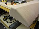
I'm using Mach v3.42.40 and getting some issues with 3D work. What I'm seeing are ridges that run perpendicular to the step over (ie. if you step over top to bottom, the ridges run left to right). Just to be clear this isn't a step over ridge I'm talking about and something else is going off here.
At first I thought I might have some backlash somewhere but the pattern is very consistent even over a large area with many hundreds of step over passes. I've also ruled out loosing steps as the overall finish piece is as intended and doesn't deviate from the original model. Lost steps would normally be very easy to spot by the end of a large 3D job. No problem with that here.
That leaves either Mach or my CAM software at fault. I use SolidCAM with a mach 3 post processor I found on the net. I've pretty much exhausted all idea's after checking the mechanics of machine and confirming these aren't at fault.
Has anyone experienced anything similar or have an idea what's going on?
Results 1 to 20 of 25
-
04-09-2013, 11:26 PM #1
 Registered
- Join Date
- Jan 2012
- Posts
- 29
Ridges in 3D work that aren't step over related
-
04-10-2013, 04:37 PM #2
Community Moderator
- Join Date
- Mar 2003
- Posts
- 35538
The only thing I can see in the pic looks like the stepover. I don't see anything wrong.
Gerry
UCCNC 2017 Screenset
http://www.thecncwoodworker.com/2017.html
Mach3 2010 Screenset
http://www.thecncwoodworker.com/2010.html
JointCAM - CNC Dovetails & Box Joints
http://www.g-forcecnc.com/jointcam.html
(Note: The opinions expressed in this post are my own and are not necessarily those of CNCzone and its management)
-
04-10-2013, 07:52 PM #3
Registered
- Join Date
- Aug 2006
- Posts
- 143
Don't be surprised if it is in fact backlash. I chased a problem like this for a while and it went away when I installed anti backlash nuts. I was convinced that it was too symmetrical to be backlash but when your contouring even a little bit is a lot.
Derek
-
04-10-2013, 09:10 PM #4
Registered
- Join Date
- Jan 2012
- Posts
- 29
Hey Gerry Originally Posted by ger21

Problem is the step direction is as shown in the arrows.
-
04-10-2013, 09:25 PM #5
Registered
- Join Date
- Aug 2012
- Posts
- 621
If you're stepping over in the direction of the arrows you've drawn in, then those lines running perpendicular to your drawn arrows would be what are normally referred to as "stepover lines". They're the tool marks left after the tool makes a pass, then steps over a bit, and makes another pass. You can make them less obvious by reducing the distance of the stepover.
Luke"All I'm trying to find out is the fellow's name on first base" -- Lou Costello
-
04-10-2013, 09:27 PM #6
Registered
- Join Date
- Jan 2012
- Posts
- 29
That was my first thought but its very consistent and independent of axis ie. doesn't matter if your stepping over in the X or the Y axis its all the same. Also doesn't matter what speed I run it at, they always appear. I usually feed at around 8-10m/min on 3D operations. As shown here: Originally Posted by derek
Back lash would also show on the corners of parts. I have none that when profiling and pocketing.
-
04-10-2013, 09:59 PM #7
Member
- Join Date
- Apr 2004
- Posts
- 5741
It sounds like your machine must be shaking a little as it's moving. A little oscillation will cause marks like that to appear.
Andrew Werby
ComputerSculpture.com ? Home Page for Discount Hardware & Software
-
04-10-2013, 10:10 PM #8
Registered
- Join Date
- Aug 2006
- Posts
- 143
What is your step over amount?
Derek
-
04-10-2013, 10:11 PM #9
Registered
- Join Date
- Jan 2012
- Posts
- 29
Hi Andrew, Originally Posted by awerby
I've tried it as low as 1m/min and still get the same.
-
04-10-2013, 10:13 PM #10
Registered
- Join Date
- Jan 2012
- Posts
- 29
Hi Derek Originally Posted by derek
0.2mm in this case but I get the same results regardless of step over. I've tried 0.1mm upto 0.5mm.
-
04-10-2013, 10:32 PM #11
Registered
- Join Date
- Aug 2006
- Posts
- 143
I'm going to end up asking a bunch of questions and then not having an answer but here goes.

The motion in the video is what I would call a parallel strategy with the motion in the ZY or ZX and the step in the X or Y. Is that the strategy that you used in the sample cut?
Derek
-
04-10-2013, 11:18 PM #12
Registered
- Join Date
- Jan 2012
- Posts
- 29
Take a look at this video, I use perpendicular strategy that follows the curvature of the surface.
The 3D work is right at the end and you can see the ridges being formed.
-
04-10-2013, 11:51 PM #13
Registered
- Join Date
- Aug 2012
- Posts
- 621
OK, your post with the arrows led me to think that your stepover was 90deg from what it actually is.
This looks like your Gcode is following line segments instead of arcs. I know nothing of SolidCAM, but I'd bet this is fixable in software, either by increasing the number of line segments or outputting arc movements to Gcode.
The CV settings in Mach could cause some jitter in curves, as well, but I'm not leaning toward that.
Luke"All I'm trying to find out is the fellow's name on first base" -- Lou Costello
-
04-10-2013, 11:59 PM #14
Registered
- Join Date
- Aug 2006
- Posts
- 143
What he said
I thought you were doing a waterline strategy. Also you may have acceleration issues as well. Ramping up and slowing down between line segments.
3D work really tests your machine!
Derek
-
04-11-2013, 12:04 AM #15
Registered
- Join Date
- Jan 2012
- Posts
- 29
Here's a section of the code
Are line segments bad for 3D and cause this sort of thing?N45 G0 G54 X788.686 Y1145.549
N50 G43 H5 Z2.
N55 G0 Z1.93
N60 G1 Z-0.07 F7000
N65 G1 X788.85 Y1146.901 Z-0.259
N70 G1 X788.891 Y1147.24 Z-0.309
N75 G1 X788.932 Y1147.578 Z-0.377
N80 G1 X788.952 Y1147.747 Z-0.418
N85 G1 X788.973 Y1147.916 Z-0.465
N90 G1 X788.993 Y1148.085 Z-0.517
N95 G1 X789.014 Y1148.254 Z-0.575
N100 G1 X789.034 Y1148.423 Z-0.639
N105 G1 X789.055 Y1148.592 Z-0.708
N110 G1 X789.075 Y1148.761 Z-0.783
N115 G1 X789.239 Y1150.114 Z-1.38
N120 G1 X789.26 Y1150.283 Z-1.457
N125 G1 X789.28 Y1150.453 Z-1.54
N130 G1 X789.291 Y1150.537 Z-1.585
N135 G1 X789.301 Y1150.622 Z-1.631
N140 G1 X789.321 Y1150.791 Z-1.728
N145 G1 X789.332 Y1150.875 Z-1.779
N150 G1 X789.342 Y1150.96 Z-1.833
N155 G1 X789.362 Y1151.129 Z-1.946
N160 G1 X789.373 Y1151.213 Z-2.006
N165 G1 X789.383 Y1151.298 Z-2.068
N170 G1 X789.403 Y1151.467 Z-2.199
N175 G1 X789.414 Y1151.552 Z-2.268
N180 G1 X789.547 Y1152.651 Z-3.179
N185 G1 X789.568 Y1152.82 Z-3.32
N190 G1 X789.578 Y1152.904 Z-3.392
N195 G1 X789.588 Y1152.989 Z-3.467
N200 G1 X789.609 Y1153.158 Z-3.625
N205 G1 X789.619 Y1153.243 Z-3.709
N210 G1 X789.624 Y1153.285 Z-3.753
N215 G1 X789.629 Y1153.327 Z-3.797
N220 G1 X789.636 Y1153.387 Z-3.861
N225 G1 X789.644 Y1153.446 Z-3.927
N230 G1 X789.752 Y1154.342 Z-4.931
N235 G1 X789.793 Y1154.68 Z-5.31
N240 G1 X789.814 Y1154.855 Z-5.506
N245 G1 X789.834 Y1155.018 Z-5.69
N250 G1 X789.855 Y1155.187 Z-5.88
N255 G1 X789.875 Y1155.356 Z-6.071
N260 G1 X789.896 Y1155.525 Z-6.263
N265 G1 X789.916 Y1155.694 Z-6.455
N270 G1 X789.937 Y1155.864 Z-6.647
N275 G1 X789.957 Y1156.033 Z-6.84
N280 G1 X789.979 Y1156.213 Z-7.046
N285 G1 X790.06 Y1156.878 Z-7.81
N290 G1 X790.07 Y1156.963 Z-7.907
N295 G1 X790.08 Y1157.047 Z-8.005
N300 G1 X790.101 Y1157.216 Z-8.202
N305 G1 X790.111 Y1157.301 Z-8.302
N310 G1 X790.121 Y1157.385 Z-8.402
N315 G1 X790.142 Y1157.555 Z-8.604
N320 G1 X790.152 Y1157.639 Z-8.706
N325 G1 X790.162 Y1157.724 Z-8.81
N330 G1 X790.409 Y1159.753 Z-11.305
N335 G1 X790.491 Y1160.429 Z-12.137
N340 G1 X790.511 Y1160.598 Z-12.349
N345 G1 X790.696 Y1162.12 Z-14.305
-
04-11-2013, 12:16 AM #16
Registered
- Join Date
- Aug 2012
- Posts
- 621
It's just a matter of resolution. What you're seeing is a curved surface represented by a bunch of long thin facets. The machine is doing exactly what it's being told to do, which is cut all those facets. If you doubled the number of facets, you'd see twice as many lines, but they would be less defined, and would tend to be less noticeable. Same thing as the jagged "stair step" lines you see when you look at a low-resolution image of a circle. The higher the resolution, the more "steps" and the less obvious they are.
As I said, I'm ignorant of SolidCAM, but it probably has a setting that can increase the resolution, or number of facets, in your geometry. That would be the most likely fix for this.
Luke"All I'm trying to find out is the fellow's name on first base" -- Lou Costello
-
04-11-2013, 12:18 AM #17
Registered
- Join Date
- Aug 2006
- Posts
- 143
They can be if your cam resolution is too course. then the line segments are too long. I work in imperial so I can't easily look at your code and tell if it's a problem. I do see that it's moving all three axis at the same time. My cam program only runs two axis and then it steps the third axis and runs again.
Derek
-
04-11-2013, 12:57 AM #18
Registered
- Join Date
- Jan 2012
- Posts
- 29
I'll have a look. I can see some settings related to motion control and tolerances including one's that set interpolation and arcs to lines.
Best thing I think is make a small 3D tool path and test changing the settings to see if the pattern changes or goes away. I'll also try exact stop to see if CV is causing this.
I'll report back, thanks for all the advice so far.
-
04-11-2013, 12:25 PM #19
Community Moderator
- Join Date
- Mar 2003
- Posts
- 35538
What did you create the model with, and what format is it? IS it a solid, or a polygon model like an .stl? As others have said, if it's a polygon model, you could be seeing the facets of the model if the resolution isn't high enough.
Gerry
UCCNC 2017 Screenset
http://www.thecncwoodworker.com/2017.html
Mach3 2010 Screenset
http://www.thecncwoodworker.com/2010.html
JointCAM - CNC Dovetails & Box Joints
http://www.g-forcecnc.com/jointcam.html
(Note: The opinions expressed in this post are my own and are not necessarily those of CNCzone and its management)
-
04-13-2013, 12:10 PM #20
Registered
- Join Date
- Jan 2012
- Posts
- 29
Hi Gerry, Originally Posted by ger21
The model is a solid done in Solidworks. I've checked the resolution of the toolpath and its 0.01mm which seems more than enough given that my machine is good to about 0.05mm. I have tried 0.001mm toolpath tolerance and but still get the same results.

 Reply With Quote
Similar Threads
-
Step jog doesn't work
By rkbuild in forum Mach Software (ArtSoft software)Replies: 5Last Post: 12-18-2012, 02:41 PM -
How does the G340 step multiplier work??
By margni74 in forum Gecko DrivesReplies: 4Last Post: 10-05-2012, 07:57 PM -
Engraving pine leaves 'ridges' where grain is
By BlueRebel in forum Laser Engraving / Cutting Machine General TopicsReplies: 3Last Post: 02-01-2012, 12:01 AM -
ridges on spoilboard when surfacing
By Dan.antes in forum Calibration / MeasurementReplies: 8Last Post: 12-15-2009, 08:23 PM -
How do vacuum chucks and vices work if all the holes aren't covered ?
By bobJandal in forum Uncategorised MetalWorking MachinesReplies: 9Last Post: 09-30-2006, 05:01 AM
