


Thanks for checkin in Ian. Some good points.Originally Posted by handlewanker

The linear slides would be a nice project but to be honest the money tree is dry and I need to wrap this project up with what I have and call it a day and get onto the next project in line. I have accumulated way to many projects and need to stop dreaming and do more doing
Im almost current. I think I have to find a couple more pics from the old days but yes, its coming up to the current build.
The electronics? YES! Its some what revamped. I have to keep the motor drives (the 320s) just to see if they work, they cost too much to trash. But the interface electronics are up to date. A Warp9 Ethernet Smooth Stepper card and a PMDX-126 breakout board. Really nice combo.
As far as the spindle drive goes I have some ideas. Id like closer to 6k rpm for the max and still have some low rpm grunt. I have a few ideas in mind. All of them include removing the R8 spindle. I have some nice spindles and bearing sets. Getting there. That might be a lil farther in the future.
Thanks again Ian for checkin inJR
Results 41 to 60 of 64
-
06-25-2013, 07:19 AM #41
 Community Moderator
- Join Date
- Aug 2004
- Posts
- 115
(Note: The opinions expressed in this post are my own and are not necessarily those of CNCzone and its management)
-
06-25-2013, 07:43 AM #42
Community Moderator
- Join Date
- Aug 2004
- Posts
- 115
Hey Jess... Originally Posted by LUCKY13
I do think they are Rockford units.
I did have some issues with the nuts. It wasnt the lil burr that you have on the tube. Mine were fouled with dirt. Not talking about massive amounts but it doesn't take much when you have ball screws. It felt gritty when cycling the screw by hand out of the machine.
I disassembled the nuts and cleaned them and all was good. Now the hand motivated travel of the axises are smooth. Be careful when doing the process. Many small balls and they ALL need to be in there. Not as bad as some nuts that have two diff size bearings (the balls). Those need to be assembled correctly.
I do have a crunching feel and sound when manually rotating the screw. But that is due to the wipers on the nuts. The lil feelers which are like a plastic brush getting wound into the screw a lil bit (1/16th of a turn at most) and is noticeable. No problem there. No interference, they are just doing their job.
Just a complete breakdown and cleaning of the nuts was the diff from night and day. Very smooth. JR(Note: The opinions expressed in this post are my own and are not necessarily those of CNCzone and its management)
-
06-25-2013, 03:13 PM #43
Gold Member

- Join Date
- Nov 2009
- Posts
- 4415
My understanding is that the quantity of balls is solely for load bearing. The diameter is for backlash control. Different size balls in the same circuit make no sense as the smaller balls would never be in contact and decrease the load carrying ability. Oddly enough a missing ball won't have any effect.
A lazy man does it twice.
-
06-26-2013, 07:23 AM #44
Community Moderator
- Join Date
- Aug 2004
- Posts
- 115
I dont know anything about ball screws or nuts. This is my first go around. For some odd reason I remember thinking or hearing about ballnuts that had staggered sized bearings (the balls). And Im not sure why, I think it was a preload issue. Originally Posted by Fastest1
I think the variation between the balls was very tight. To where you needed to Mic the balls out to see the diff. But the diff was there so you separate the balls into their sizes and load the nut up.
Im not even sure if the odd ball size thing in the circuit is real or I made it up LOL
BUT! Think about it. If the balls are very close in diameter but off by .002" they would tend to "stack up" in the race right. If the race had the room for them to stack. The stacking (a lil off center) of the balls would make them ride in the race fixed to their points of contact? It forces the balls to the sides of the race and makes a zero lash type of bearing.
I dont frickin know lol. Just seems like staggered sized balls would create some side loads for the balls in the race and do something like a preload. Hahaha.. Im just spitballing here. I honestly dont have a clue.
The nuts I have use the same sized balls and I use two nuts for each screw. The nuts are being preloaded with springs. IMO it will work just fine for my small hobbyist machine.
Im not a machinist. Im just an old retired guy trying to have fun with my time
I DO appreciate the great replies guys. Thank You. JR(Note: The opinions expressed in this post are my own and are not necessarily those of CNCzone and its management)
-
06-26-2013, 02:51 PM #45
Gold Member
- Join Date
- Nov 2009
- Posts
- 4415
You will enjoy the performance of ball screws just like they are most likely.
I too am an amateur in this arena. I have disassembled and reassembled a few ballscrews now. The balls were always the same size (though I have read about staggered sizes but no explanation of why).
To remedy backlash, I have seen people reball their screws. They get balls in the next biggest size (or larger). My screws have always remained less than .005. Backlash comp takes care of it just fine.A lazy man does it twice.
-
06-26-2013, 05:35 PM #46
Member
- Join Date
- Sep 2006
- Posts
- 6463
Hi, if you compare a ball screw with a ballrace you'll understand how they function and need to be utilised.
First, a ballscrew with a single nut is like a deep row ball race except the radial track in the outer race of the ballrace is a spiral track on the ballscrew, and like a deep row ballrace only carries axial loads ....because it can, which is actually a bad design but it does work ....for a while.
In order to function as a bearing without friction a deep row ballrace (and all ballraces) MUST have the balls caged to prevent them rubbing against one another as the inner race rotates and be subject to radial loads not axial loads......they can take some axial loads, but not for long, and not by design.
Once a deep row ballrace becomes worn it has slop not only in the axial direction but also in the radial one too, and being used to carry axial loads accelerates the wear.
The same occurs with the ball screw, except the balls are not caged and rub against one another as they migrate through the spiral of the screw/nut interface.
A ball screw with a single nut, like a deep row ballrace, initially is a good fit, WITH BALLS OF A SPECIFIC DIAM, and it will carry axial loads when new in both directions without perceptible backlash, but this does not last for long, and after a short while you have backlash, even though the ballscrew is running smoothly.
To overcome this, two ballnuts are fitted to a screw and are spring loaded axially to force the balls to run in the corner of the thread form and so eliminate the backlash.....the spring loading applies a force axially to keep the nuts pressed against the thread on opposite sides so that you can move the nuts axially forward or back without any lost travel.
But we still have the characteristics of a deep row radial bearing without a cage and balls crowded together and rubbing against one another, also without the sealed in lubrication of a deep row ballrace, so wear is accelerated, but taken up by the spring loading to a degree.
It is possible, under loading, to overcome the force of the springs and have some backlash when in the reverse travel.
All ballscrews are subject to axial loads, not radial loads, and the size of the balls is critical to the backlash quality in a single nut, but not in a double nut.
In fact, for smoother running it is better to have slightly smaller balls in the nuts than larger ones, PROVIDED you have two nuts per screw with spring loading or precision selected sized spacer washers between the nuts........which is an attempt to emulate an angular contact bearing arrangement.
The ballscrew is a distant cousin of the deep row ballrace, but not having a cage to separate the balls in their movement or sealed in lubrication with seals, is a very poor design compromise that works if they are used in pairs.....there can be no exception to that rule.
It gets worse when the screw is rolled instead of being precision ground, but the cost difference is the deciding factor, despite the longer life span of the precision ground variety.
You are looking at ballrace technology in every aspect when a ballscrew drive is being decided on.
Ian.
-
06-26-2013, 06:05 PM #47
Gold Member
- Join Date
- Jun 2004
- Posts
- 6618
And yet they work so well when properly implemented and lubricated.
I have NSK ground ball screws on my 80/20 mill. They are single nut with two size balls. That said, they are nearly identical in size. Maybe .002"difference. I use heavy weight oil in these. They were used when I got them, but still in good shape.
I gave them a good cleaning. That said, my X axis way cover was pretty poor and a few chips did get inside with that design. I found another exact duplicate on Ebay cheaper this time, but appeared unused.
I simply swapped them out and have now had time to clean out the spare and replace the balls. I also updated the way cover design and it works better as well.
Oh, and I cannot measure any backlash with my indicators. That is hard to beat for the price. You just have to know what you are looking for and sometimes take a chance on Ebay, but deals are there to be had for the vigilant.
Lee
-
06-27-2013, 04:24 PM #48
Member
- Join Date
- Sep 2006
- Posts
- 6463
Hi, correct me if I'm wrong, but when you have two different size balls in a ball nut the smaller balls do not carry any load but act as seperators for the load carrying balls and are placed alternately in the line so that they can counter rotate between the load carrying balls without being hard driven against one another as happens normally when balls of the same size butt against one another.
This is only a wear reduction solution and you still need two nuts to have zero backlash.
Ian.
-
06-27-2013, 05:31 PM #49
Gold Member
- Join Date
- Nov 2009
- Posts
- 4415
Makes sense in that light.
A lazy man does it twice.
-
06-30-2013, 02:44 PM #50
Gold Member
- Join Date
- Jun 2004
- Posts
- 6618
The reality is that it doesn't allow backlash until they are worn. They pack in very tightly and fill the entire track or race. There is virtually no displacement of the balls during a direction change and this is what allows zero backlash. Virtually I mean. Certainly there must be some, but I cannot measure it with the tools I have. This then is essentially zero backlash for my needs. I do use double opposing nuts on my other machines with rolled ball screws to achieve the same.
Lee
-
07-03-2013, 06:23 AM #51
Community Moderator
- Join Date
- Aug 2004
- Posts
- 115
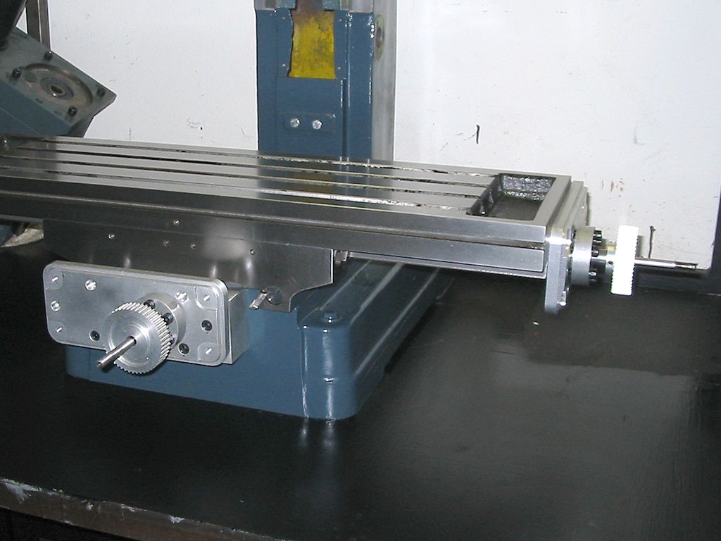
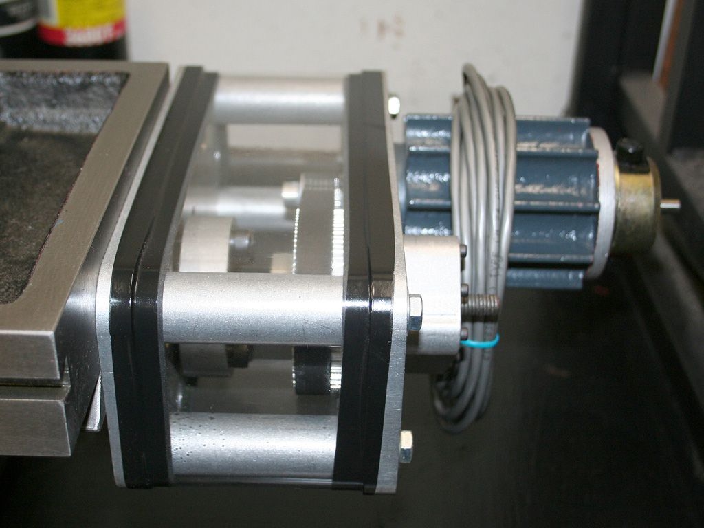
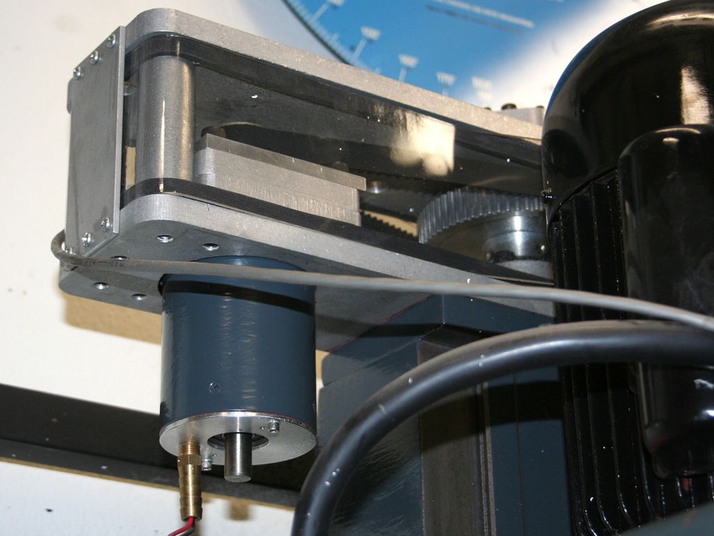
More pics. The table on after the ball screw nuts and screws were mounted. One part I didnt talk about was the ball nuts were wrapped in heat shrink tubing to help keep "junk" out of them. I wish I would have made provisions for oiling of the nuts/screws. I have a feeling the entire assembly will be apart again to plumb some lines to them. Live and learn, I hope
Table back on.
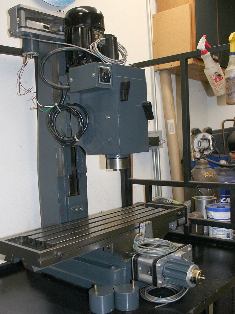
So YES! handlewanker This is the final look of the machine as of this month. Finally right LOL I have done some work that is current and will sort out those pics. It was a chore to find all the old pics and figure out what to write. Its kinda a drag to post old pics and try and think of something to say. But now that it is current work I can just lay into it and bore the hell out of you guys with my tendancey to run on with talk
As she sits today.. More to follow but prolly not any faster due to the snails pace at which I travel with my projects. I will try to keep it worth reading though. Really sorry for the old stuff I posted but to make it a story I thought I should show how it evolved to the point where it is now. It had a beginning and the story should start at the beginning. Bear with me folks
Sitting after six years of neglect. She will get some life giving electrical energy within the year I hope. Ok, thats a lil far fetched optimism JR
 (Note: The opinions expressed in this post are my own and are not necessarily those of CNCzone and its management)
-
07-04-2013, 05:12 AM #52
Member
- Join Date
- Sep 2006
- Posts
- 6463
Hi, looking very good so far.....pretty neat assembly.
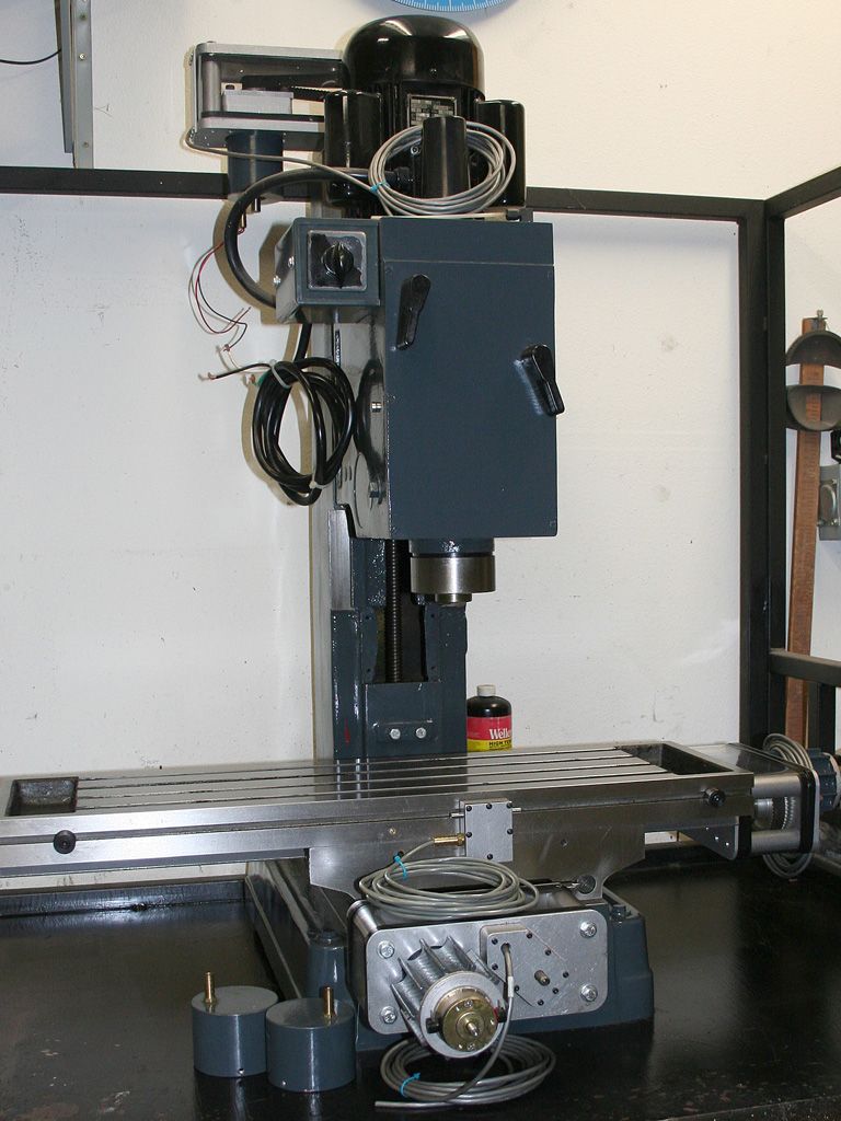
Looking at the third photo in this post gives me an idea for an ATC design......it has an open disc like carousel that is attached to the left side of the column with two arms top and bottom, and in operation the whole carousel swings around and under the spindle centre line and then rotates to select the desired tool.....the spindle just deposits and acquires the tool as needed by going up and down.
This is similar to the action of the static tool magazine that is attached to the end of the table (but needs table space), and rapid table X & Y travel to get the magazine under and away from the spindle centre line etc which absorbs many seconds of operation time to just change one tool, but is simple and effective.
The tools could be to any shank design as they would be inserted tool point down into the carousel full circle holes, so that means you don't need to have a groove round the shank collar, just the same diam collar on all tools to keep them in the same position for spindle centre alignment.........provided the tools all have a diam less than the collars, which makes it awkward for placement of larger diam facing cutters etc.
It probably has been designed before, as practically anything that can move has been used in one form or another......I just haven't seen it, so it seems like a simple plan.
BTW, have you planned on the gas struts for the z axis .....with a cast iron casting head and motor weight on the Z you will need some assistance for counterbalance.
As this is going to be a fairly slow build, I would consider eventually having the dovetails milled off and fitting linear ways to all slides....the difference in performance would be exponential in the travel speed rapids capability, stepper motor load reduction and slide positional accuracy.........just the Z axis alone would benefit enormously.
It's the difference between designing a piece of equipment with bronze bushes or ballraces.
Ian.
-
07-04-2013, 01:53 PM #53
Gold Member
- Join Date
- Feb 2006
- Posts
- 7063
So.... Kinda like this:
My Bridgeport Mill Toolchanger - YouTube
2012-11-27_13-30-42_528.mp4 - YouTube
Moving a full carousel is not the best idea in the world. The above works ok, but my new 12-tool ATC, which I'm designing and building for Novakon, has a fixed carousel (next to the column, completely out of the way), and a servo-driven transfer arm to moves the tools back and forth. A fully loaded carousel can be quite heavy, and moving and positioning that much mass smoothly, gracefully, and accurately and consistently can be quite a challenge. The fact that the mass can vary greatly depending on which tools, and how many tools, are loaded, makes it even worse.
Regards,
Ray L.
-
07-04-2013, 03:01 PM #54
Registered
- Join Date
- Aug 2008
- Posts
- 187
David Decaussin has a fantastic new ATC for his mill.
-
07-05-2013, 05:26 AM #55
Member
- Join Date
- Sep 2006
- Posts
- 6463
Hi I quite agree about the weight factor, and as they say, nothing has ever been not done before or thought of by someone else....LOL.
Ian.
-
07-05-2013, 08:19 AM #56
Community Moderator
- Join Date
- Aug 2004
- Posts
- 115
Photobucket ERRR!
") JR
(Note: The opinions expressed in this post are my own and are not necessarily those of CNCzone and its management)
JR
(Note: The opinions expressed in this post are my own and are not necessarily those of CNCzone and its management)
-
07-05-2013, 10:02 AM #57
Registered
- Join Date
- Nov 2007
- Posts
- 980
Forgive me but why can't you just upload them here directly as it's free to do? Originally Posted by JRouche
DaveDave->..
-
07-05-2013, 03:03 PM #58
Gold Member
- Join Date
- Nov 2009
- Posts
- 4415
I have wondered why people don't post direct. It is distracting being forwarded to another site. Of course most of my posts are from my phone so it is effortless.
A lazy man does it twice.
-
07-05-2013, 05:20 PM #59
Member
- Join Date
- Sep 2006
- Posts
- 6463
Hi, What's the advantage of PB anyway?
All of my photo posts were on here direct, no cost etc.
I suppose it means anyone can view your photos without having to be on this forum, like being on UTUBE.
Ian.
-
07-05-2013, 06:28 PM #60
Community Moderator
- Join Date
- Aug 2004
- Posts
- 115
Well? I bit the bullet and had to pay for the unlimited bandwidth. I use PB because I have many sites I upload photos (links) to. Its a convenience issue. Cnczone is just one of prolly 15 sites I post to. And it seems the bandwidth is over 10G a month. So if I wanna play I gots to pay
JR
(Note: The opinions expressed in this post are my own and are not necessarily those of CNCzone and its management)

 Reply With Quote


Similar Threads
-
Enco vs. Grizzly square column mill
By kc6uvm in forum Benchtop MachinesReplies: 15Last Post: 10-11-2012, 07:16 PM -
Enco RF-45 clone CNC convertion.
By LUCKY13 in forum Vertical Mill, Lathe Project LogReplies: 18Last Post: 04-26-2012, 07:54 PM -
enco 45 square column mill
By atomize in forum Benchtop MachinesReplies: 11Last Post: 10-19-2008, 09:46 AM -
Enco Square column onsale w/free shipping
By JRouche in forum Benchtop MachinesReplies: 3Last Post: 05-07-2007, 06:44 AM -
HARBOR FREIGHT small round column mill to a square column conversion.
By motomitch1 in forum Vertical Mill, Lathe Project LogReplies: 25Last Post: 12-01-2005, 05:24 PM
