


What was next?? Oh yeah. The concrete fill for the base. There were some guys talking about damping and vibration even back in 2005. Some were using epoxy and various grades of gravel. I like it. Mass = stability right?
Problem for me is I could not afford the massive amounts of epoxy. Its not inexpensive. I looked for some other fillers that were less expensive. I went with concrete. At the time there were only a few suppliers of Ultra-high-performance concrete (UHPC). It was a new item then. And still is for construction.
But in 2005 there was a product that was close. HardBlok. An engine block filler for racers. It has some great thermal and mechanical properties so I used it. And it was with in my budget. Pics??
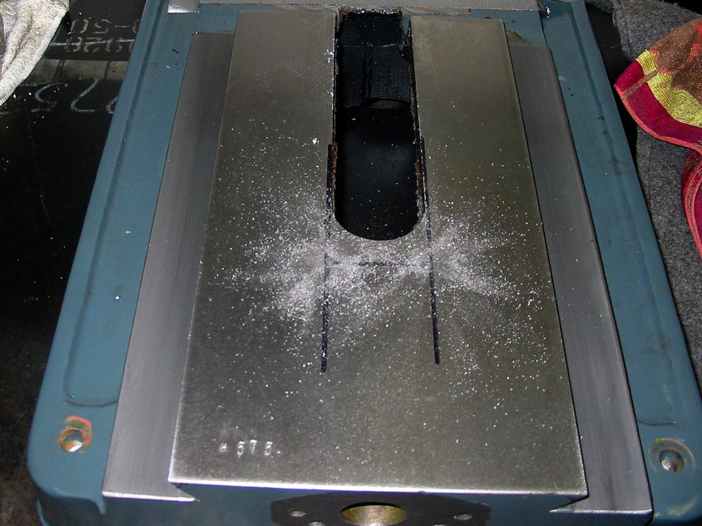
Prepping the base for the fill. Some solvent cleaning IS a must. Remove all the oils. I like acetone.
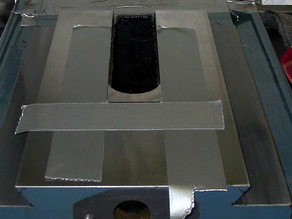
Then I taped off all the sections where I did not want the concrete to go.
More blocking with a simple cardboard box.
Some grease for release of the box.
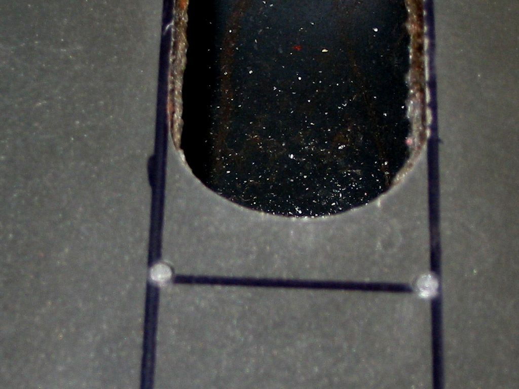
Form in place and the concrete poured.
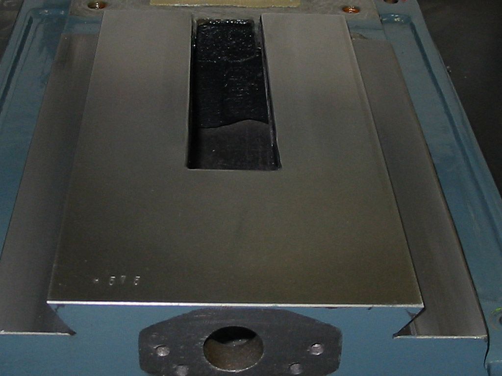
Form pulled..
Some spray paint to use up one of too many cans I have.
Fast forward. The concrete is still there. Havent use the Mill yet but the concrete is still attached. JR
Results 21 to 40 of 64
-
04-14-2013, 05:42 AM #21
 Community Moderator
- Join Date
- Aug 2004
- Posts
- 115
(Note: The opinions expressed in this post are my own and are not necessarily those of CNCzone and its management)
-
04-15-2013, 04:01 AM #22
Community Moderator
- Join Date
- Aug 2004
- Posts
- 115
Y-Axis travel modification. Thanks to Aaron of Industrial Hobbies. He showed a mod of the base to increase the Y-axis travel slightly. And it doesn't give a whole lot of extra travel but any lil bit helps.
Basically it allows the ballnut mount more room for travel before it hits the base. I did the cutting of the base and made the thicker motor mount. JR
Pics...
Marking and drilling the corner holes...
Taping the lines for the cut. Duct tape is good to go..
An abrasive saw (4") for the cut.


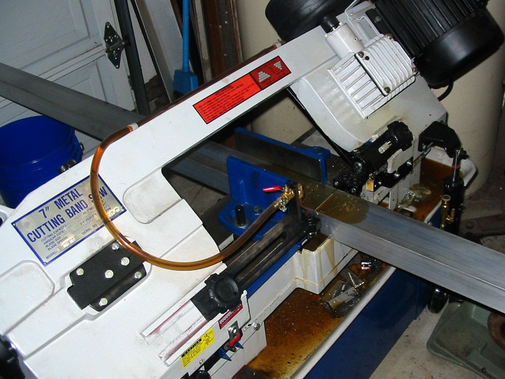
Some long bar stock being sliced off for the thicker spacers. Love my bandsaw..
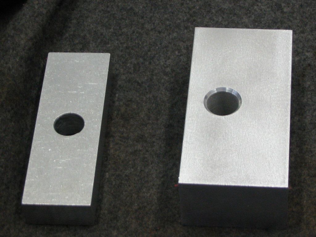
The original spacer next to the new one for the extra Y travel..
JR(Note: The opinions expressed in this post are my own and are not necessarily those of CNCzone and its management)
-
04-20-2013, 03:41 AM #23
Community Moderator
- Join Date
- Aug 2004
- Posts
- 115
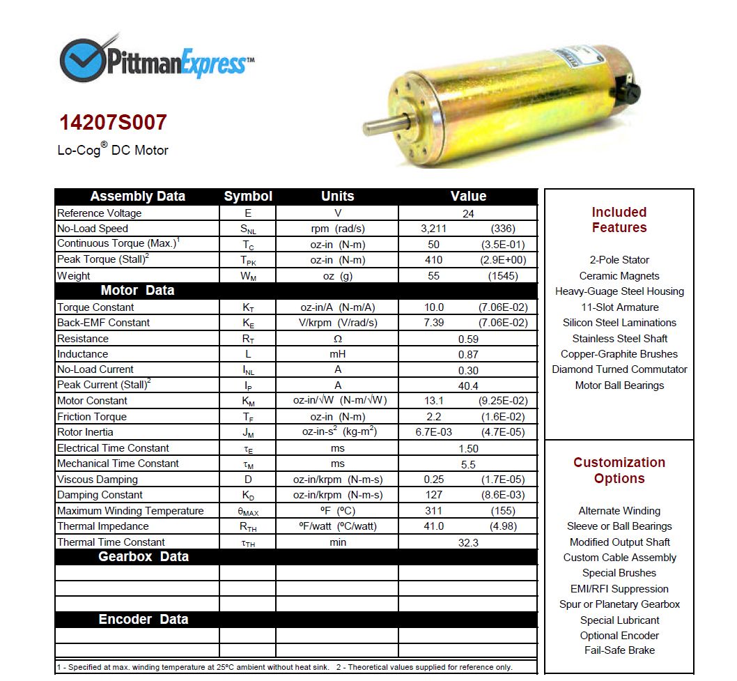
Here is the info on the X/Y motors. JR Originally Posted by Winnfield

 (Note: The opinions expressed in this post are my own and are not necessarily those of CNCzone and its management)
-
04-21-2013, 04:22 AM #24
Community Moderator
- Join Date
- Aug 2004
- Posts
- 115
Next up? The bench and enclosure. I don't have any room left in my garage so it was time to eat away at the horizontal space I did have. My welding table!! Sucks cause its overkill for a mill stand. I didn't like loosing the area that I need for welding. All TIG welding on the table. My old transformer Hobart Tigwave is massive and even though its on a wheeled cart its not moving anywhere. Its stuffed into a corner and has to stay where it is, right next to the welding table.
BUT... I need the horizontal surface so solly welding, time to sacrifice. The table is 3'x8' and 1-1/2" thick mild steel. Its mounted on four 4x4 tubes that are a 1/4" thick and bolted to the floor.
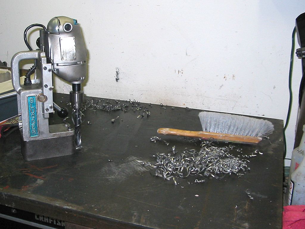
Drilling the holes for the mill base and flood coolant lines was NOT gonna be done with a hand held drill motor. The holes were 1/2" for the mill base and 1" for the coolant. Time for a portable drill press. Mag drill actually. Been looking for a need for that darn thing. Its also old but has some grunt. It powered the 1/2" and 1" drill bits right through the table.
The next step was the frame for the enclosure. I used some 1-1/4" square tube for the frame. I have some 1/4" lexan that I want to use for the four sides. Its not the way to go unless you happen to have some polycarb sitting around. Just as secure and less expensive would be to use some steel, aluminum or even some counter material like formica. There is no reason it needs to be see though for the sides and back. The front? Prolly.
It is not even close to being done. The holes are drilled and half or less of the frame is welded up. I want to wait to weld up the entire enclosure so I have access to the mill while doing the work on it.
Some pics???
Measuring the area for the placement of the mill. Its critical! LOL Ok, not so much. But sorta.
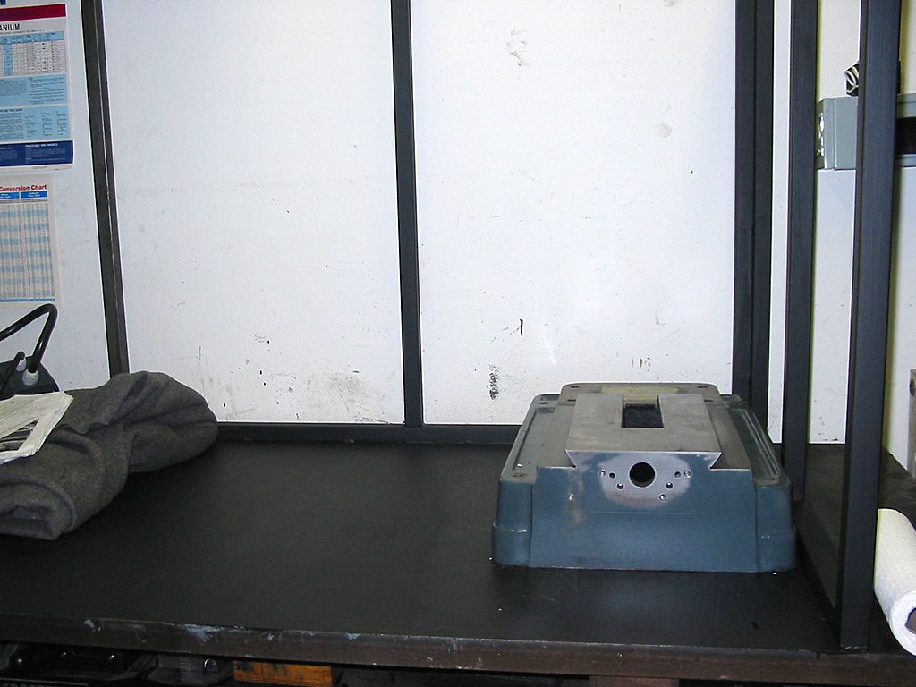
Next up... Drilling the holes. The old mag drill knocked it out. This thing has more torque than my clausing 20" drill press. Its an animal. It drove the 1/2" and 1" bits through like butter.
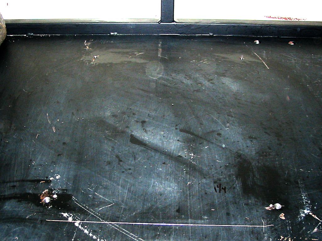
Holes done. NEXT!!!
 (Note: The opinions expressed in this post are my own and are not necessarily those of CNCzone and its management)
-
04-22-2013, 04:26 AM #25
Registered
- Join Date
- Dec 2006
- Posts
- 839
Wow, I don't know why I have never thought of the block filler for this. This product is made for stiffening up the cast iron blocks, so it should work a treat. I cant remember what this stuff would add in weight?
Man, 1 1/2" steel plate! She is not going anywhere.
That is one beautiful mag drill!
JessGOD Bless, and prayers for all.
-
04-22-2013, 05:03 AM #26
Gold Member


- Join Date
- Feb 2007
- Posts
- 4553
 Great Idea
JRouche,
Did the grease alone keep the wet Rock Blok from running under the box along the edges?
Nice work!
Jeff...Patience and perseverance have a magical effect before which difficulties disappear and obstacles vanish.
-
04-23-2013, 05:56 AM #27
Community Moderator
- Join Date
- Aug 2004
- Posts
- 115
Hey Jeff, good point. But I think it was just the snug fit of the box. And I dont remember where the box came from. Just happened to have a box that fit perfectly. Weird right, I think I did shorten it though. The mix was a pretty thick one. Look at the front of the base. There is a gap between the box and casting and the mix didnt flow down into that gap. Sometimes I get lucky and Lord knows, I need as much luck as possible cause the skill side is a lil weak sometimes Originally Posted by jalessi
 Thanks Jeff. JR
(Note: The opinions expressed in this post are my own and are not necessarily those of CNCzone and its management)
Thanks Jeff. JR
(Note: The opinions expressed in this post are my own and are not necessarily those of CNCzone and its management)
-
04-23-2013, 06:18 AM #28
Community Moderator
- Join Date
- Aug 2004
- Posts
- 115
Right Jess? Thats what I thought. If its good enough for an engine it should work somewhat for the mill. I didnt weigh it but the stuff is dense. I thought about doing the column but the masking off process and the additional cost was just not in the books. Originally Posted by LUCKY13
The 1-1/2" table should hold the mill up right?? Hahha.. AND.. Its only a couple of holes so if I need to move the mill it can happen. The table is so stout that shedding the enclosure with a grinder wont be a big deal.
The mag drill? YES! Its old but its crazy how much torque those motors have. I have about 30 brand new hougen rotabroach annular cutters. Those things are very sharp and cut even faster than the S&D bits. But I just needed some holes and not some fine dimensional holes. I have actually had great results with greenlee hole saws in thick material but I didnt have any long enough for this cutting job.
Thanks for checkin in Jess. JR(Note: The opinions expressed in this post are my own and are not necessarily those of CNCzone and its management)
-
05-29-2013, 07:15 AM #29
Community Moderator
- Join Date
- Aug 2004
- Posts
- 115
Ok.. Pretty bad (on me) when I have to scroll down five pages to find my post. I need to be more active.
In my defense I have been looking. For the old pics to write about but I either didn't take any or cant find them I have been looking through the computer for the old pics and cant find ANYTHING of value. I know I took many. It was still the digital age but I did change over cameras around the same time.
I have five terabytes of storage on the computer and have searched the entire thing. Didn't find what I wanted to bring the story from back then (2005ish) to now. So Ill just have to toss up the pics that I have and get to where it is now.
And its still a slow go. I work on it everyday (m-f) and get a lil at a time done. So it will still be a slow show but active.
Lemme post some more 2005-2006 pics with descriptions.
Refresher for those that are showing up. A nice IH (Industrial Hobbies) CNC conversion for the RF-45 type mill. Its old, 2005 era and still not done. And that's because I'm swamped and slow. My projects run in decades not years or months.
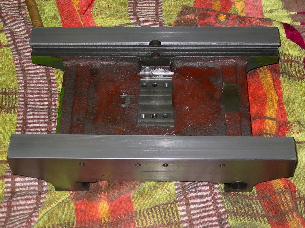
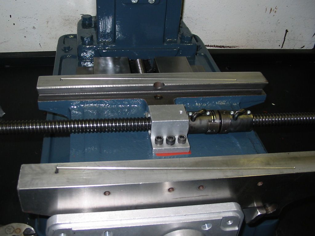
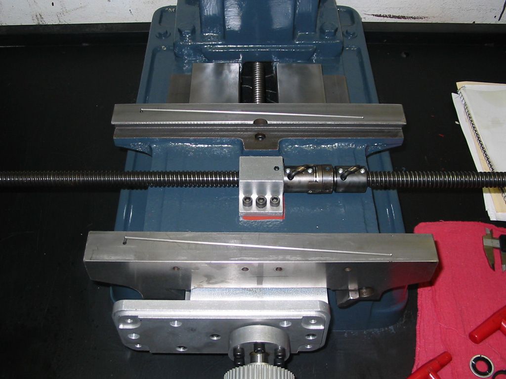
Setting up the carriage for the Y axis ballnut mount.
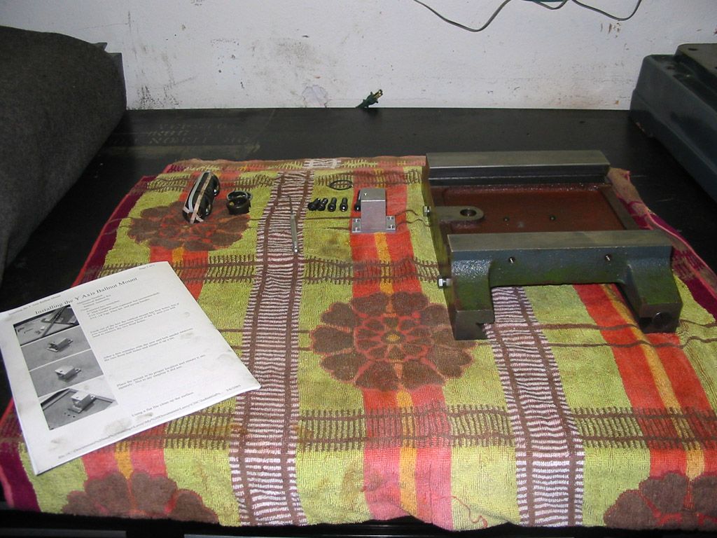
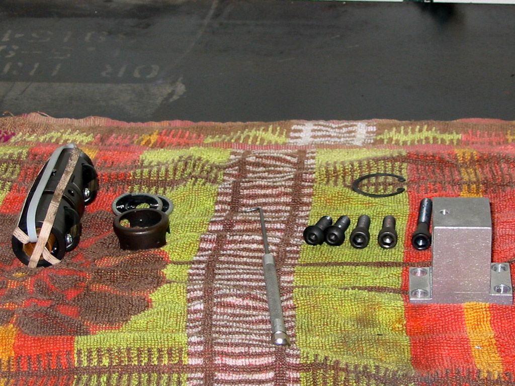
I KNOW. Lame to not show the work needed to mount the ballnut mount. Again. I failed to save or take the pics. I totally missed the mounts for the drive up front. And it appears I had the provided spacer for the Y travel but did extend the Y travel slightly and made up a new aluminum block spacer. That was the cutting of the base pics before.
Solly for the wacky time lines and pics folks. Im just tossing out what I have to get this post up to speed to where it is now. Z axis and its weak looking mount next.. JR(Note: The opinions expressed in this post are my own and are not necessarily those of CNCzone and its management)
-
05-30-2013, 05:56 AM #30
Community Moderator
- Join Date
- Aug 2004
- Posts
- 115
Again, some 2005-2006 pics to catch up.
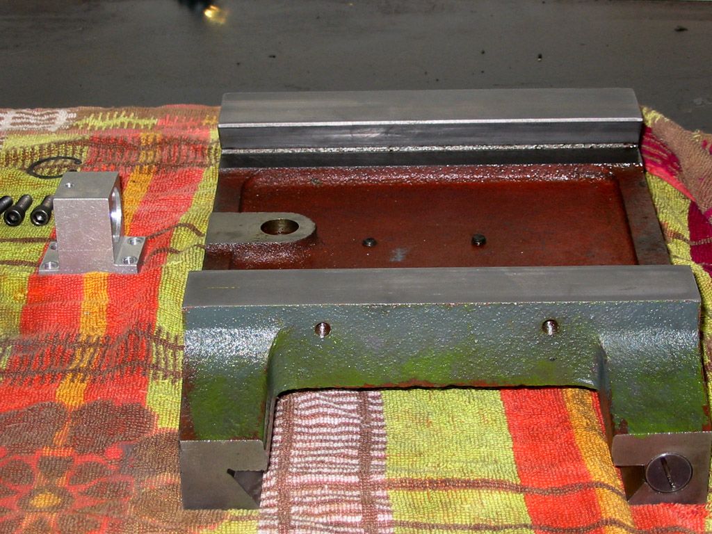
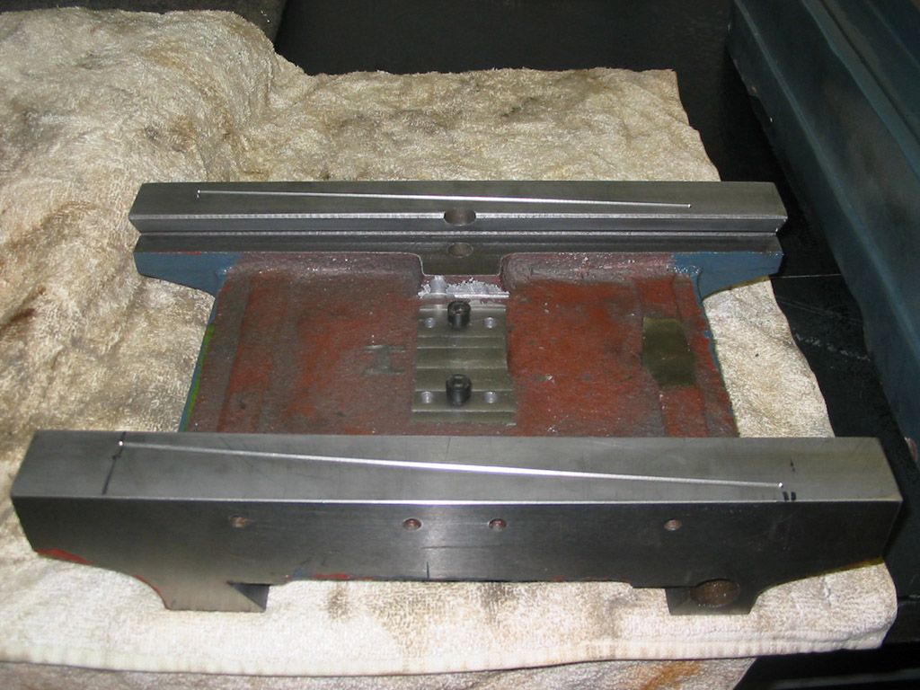
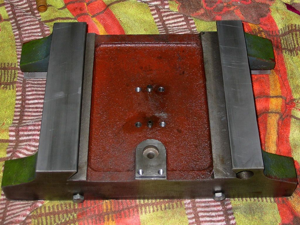
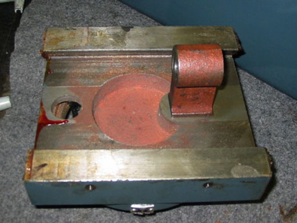
Some additional pics of the saddle. I showed this one before but forgot to mention besides milling the ballnut mount mounting surface flat (and that lil H looking section that was high) I had to grind one rib (on the right side) a lil for clearance of the ballscrew. Shouldn't be a big deal for rigidness.
And again the oil grooves. I honestly didnt know how to do it so just did the best I could. After seeing some others there are better methods. One thing I failed to do was supply oil lines and ports for the ballnuts. That may come back to bight me in the future. I recommend it if you can.
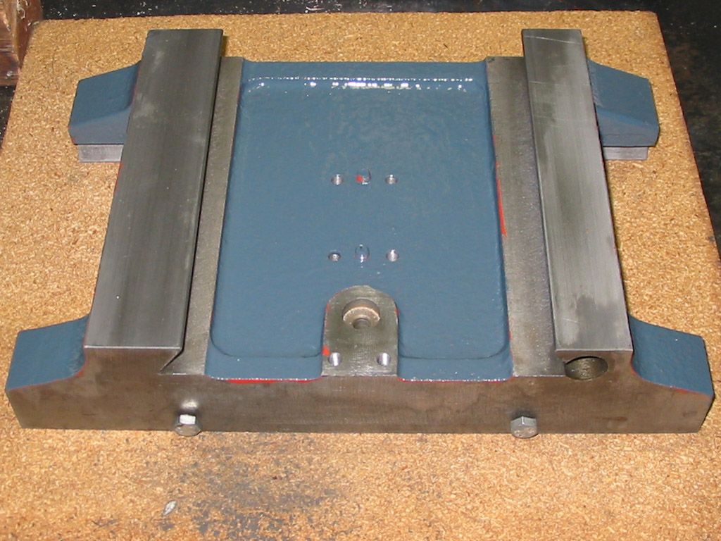
Before and after with a lil paint added. They didnt have very solid paint on it and it looks like they used a couple of colors
 (Note: The opinions expressed in this post are my own and are not necessarily those of CNCzone and its management)
-
05-30-2013, 06:20 AM #31
Community Moderator
- Join Date
- Aug 2004
- Posts
- 115
Some shots of the Z slide. There have been many improvements in this area over the years for this type of mill. For example the IHs mill has a much larger and IMO better Z-axis slide as do some of the newer mills out..
Here is the original screw. Brand new. I thought I saved it and looked for it cause a member was looking for all three screws but I just cant find it in the mess that I call my shop
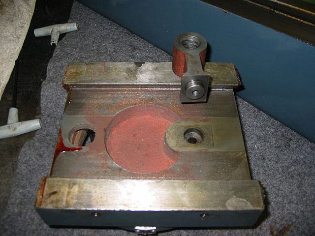
Here is a weak point I think. The screw nut is cast iron. The IHs kit had me reuse it for the ballnut mount. The vertical web is not all that beefy so Im hoping it doesnt break.
But worse yet is the area where it is accepted to the Z saddle. Its not as large as many of the other RF-45 type mills I have seen. Time will tell..
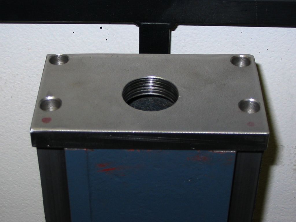
The top of the column was cleaned up and prepped for the Z-axis mounting plate.
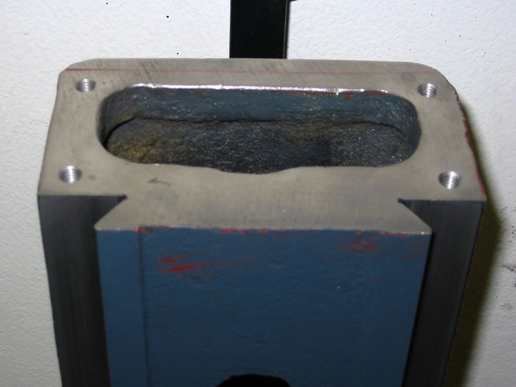
BUT... For reasons unknown to me (old age and amount of time elapsed) I made a rather large steel mounting plate that was not part of the kit. My only guess is there was not enough meat on the top of the column to mount the IHs base plate. Just guessin..
 (Note: The opinions expressed in this post are my own and are not necessarily those of CNCzone and its management)
-
05-30-2013, 07:33 AM #32
Banned
- Join Date
- May 2013
- Posts
- 0
Im not sure but Ill let ya know what I did


-
05-31-2013, 07:09 AM #33
Community Moderator
- Join Date
- Aug 2004
- Posts
- 115
Hey guys. Found some more pics to upload from way back.
Also did some work on it today. I really wonder if this whole machining thing is suited for me. I literally made three parts for the one part I needed due to oversights (fancy word for mistakes). I dont draw up plans with measurements. I just look and make. Well lemme say! Thats not working out so great.
Not a major loss. Small material use (which goes back in the ready made section for future projects LOL) And not a time issue, Im retired. But it is a hit on the mental side.
So anyway. Dug up some pics..
Going backwards from what I have shown I wanted to show the column to base mounting. The base of the column looked pretty bad. Here is a partial shot. Its looking rust and crusty.
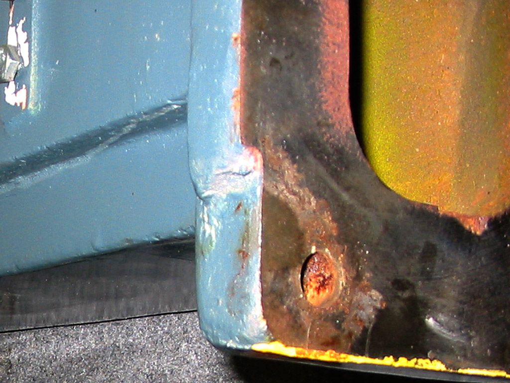
With some scotch bright pads and WD-40 it cleaned up pretty well. All I did was scuff the surface with the pad, no metal removal.
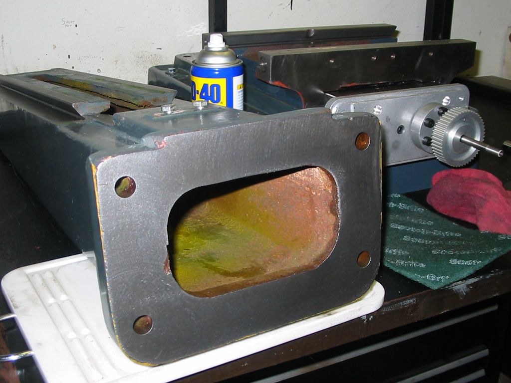
Getting ready to set the column back on top of the base. The base was cleaned in the same way. It was heavy, the column. I had to hop up on the table to set it in place.

New bolts and all the filler removed from the column to get a metal to bolt face fit. Its crazy how much filler is on these machines. And Im not new to the filler use idea. I have some old 1950s machines made in the USA that have filler. But not on this scale.

After bolting the column up to the base I wanted to see how perpendicular (AKA square) it was to the table. Im not even sure if it was all that accurate, my method. I did the best I could to use the blocks. Made sure every surface was spot clean and the blocks are pretty nice ground blocks. So with the square at the top of that mess of blocks the column showed to be completely within my tolerances. I could not discern any shift of the column, no shims needed. I was ready to shim it for "for and aft" column issues. Side to side? I couldn't think of a way to do it, back then. These days I could put a round in the V and gauge off it I think.
But honestly. Im not looking for perfection. I just wanted to make sure it was not tilting much. It was dead on from my perspective.

JR(Note: The opinions expressed in this post are my own and are not necessarily those of CNCzone and its management)
-
06-14-2013, 06:24 AM #34
Community Moderator
- Join Date
- Aug 2004
- Posts
- 115
I did find a couple more pics. See how long it takes me just to load some old pics??? No wonder this darn project is taking so long
JR
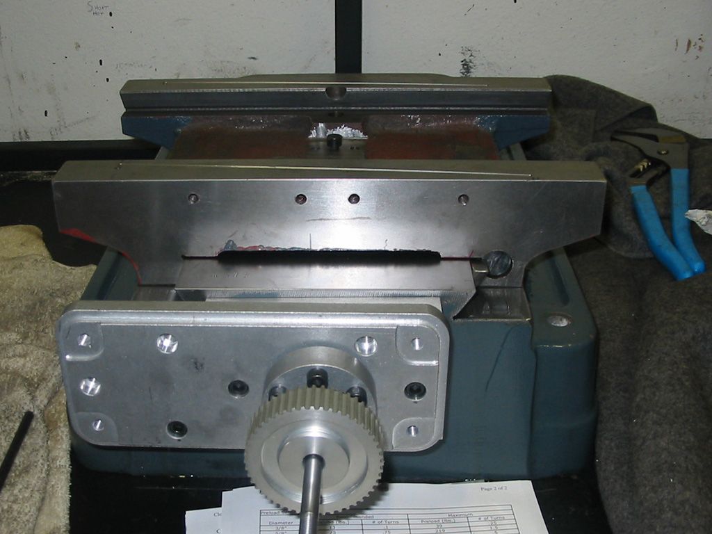
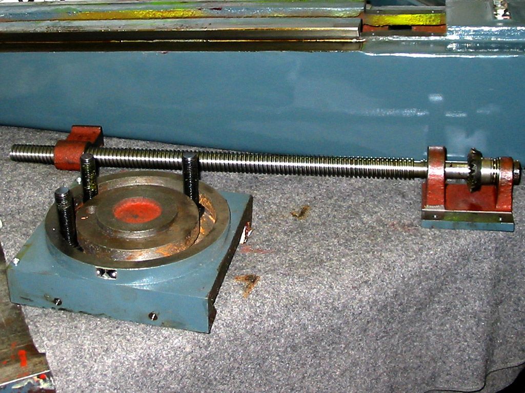
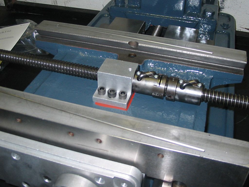
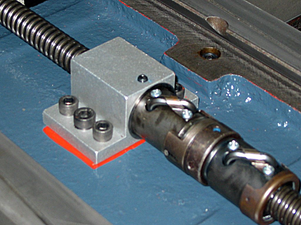
Anyway, not useful for a how it was done type pic but its kinda self explanatory, I think, Hmm.
The table ballnut and mount. The ballnuts are some nice units and have adjustable preload. They are basic single circuit nuts mounted together as one to make a double circuit nut by Aaron.
 (Note: The opinions expressed in this post are my own and are not necessarily those of CNCzone and its management)
-
06-14-2013, 03:03 PM #35
Gold Member
- Join Date
- Nov 2009
- Posts
- 4415
Isnt it ironic my user name and the pace at which I finish a project? You and I have alot in common. Now let me go find the drivers for that other project before the 3D printer, mill, lathe, new house, 3 kids, horse, oh **** I have a horse? Well you get the idea.
-
06-14-2013, 05:42 PM #36
Community Moderator
- Join Date
- Aug 2004
- Posts
- 115
Hahaha!!! YUP.... JR Originally Posted by Fastest1
(Note: The opinions expressed in this post are my own and are not necessarily those of CNCzone and its management)
-
06-18-2013, 01:29 AM #37
Registered
- Join Date
- Jan 2009
- Posts
- 265
Thats a nice kit, although, I could imagine the aluminum nut mounts buckling under the loads of a collision.
Maybe later in the years i personally would be remaking those with iron or steel.
Good build!
-
06-18-2013, 04:34 AM #38
Member
- Join Date
- Sep 2006
- Posts
- 6463
Hi, just read all the posts.......I think I would be tempted to mill off the dovetails and fit linear ways....how practical that is for you I don't know, but having it down to the last nut and bolt and also a Bridgeport to do the work seems like a retrograde step not to do it.
BTW, you're doing great so far, even though you say you aren't trained for the work........I blanched at the lapping of the ways bit, (Shock horror), but that's just a case of whatever it takes etc.
I take it that from this point on it's a current build program, the previous having been a step back in time to the dim and distant 2005 period in history.
As the years have gone by, I think you should take a good look at the electronics side to see if anything that might need to be replaced (7 years) is still available.
I didn't see any specifications as to the requirements for the build..... that is... the job side of it, and this will determine the drive that you need for the work.
The original drive was orientated to manual milling....chunk a chunk a chunk, whereas the new build would need a whole different approach.......7,000 rpm would be nice.
Ian.
-
06-23-2013, 07:14 AM #39
Registered
- Join Date
- Dec 2006
- Posts
- 839
The ballnuts and screws look exactly like the ones I have , Aaron must of been using Rockford for his supply.
I had a small problem when adding preload they would get a rough feel to them if I added a lot of preload (more like a catch). What I found was the balls would catch the little tit on the end of the transfer tube when they circulated up into the tube. I have not corrected it yet but I expect a touch of a grinder on the end of the tube would fix it ( sander really it needs to be smooth or it would cause wear).
I have not done it yet because I felt like I would wait and see if I even needed the amount of preload that I ran into a problem with. Going by doc's and info from Rockford I will need the preloaded amount I was working with but until I see it running on the machine I don't feel I know for sure. It is possible my wavy springs are stronger than they think, or maybe even I got the wrong springs with the set when I bought them.
Anyway if you run into them feeling like they want to lock up this would be where to look for a problem. I guess we do not need any more preload than the machine needs to hold backlash out when under a load. Anymore than this would be wasted wear on the parts. But by Rockford's info I would be at what they consider light preload at the point I started feeling the problem. I will see when I get there.
JessGOD Bless, and prayers for all.
-
06-25-2013, 06:09 AM #40
Community Moderator
- Join Date
- Aug 2004
- Posts
- 115
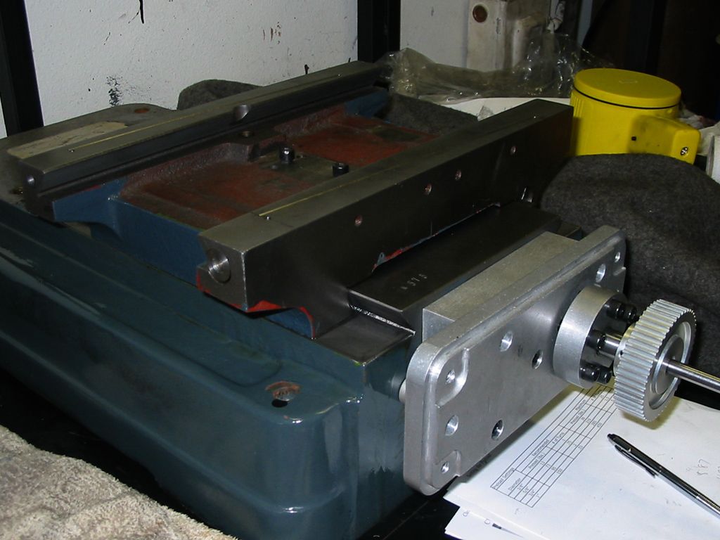
Thanks... Yeah, the aluminum ballnut mounts do look a lil light. Kinda hard to see with my pics but they are pretty substantial. The flat part (the wings) are .250" aluminum and the body is a lil thinner. Originally Posted by D.L
Im hoping they hold up to the use I will need. And YES. A crash is almost certain in my future LOL So we will see. I think there are a few of these kits out there and I haven't heard of the nut mounts failing.
Maybe my post will be the first one Thanks for checkin in. JR
(Note: The opinions expressed in this post are my own and are not necessarily those of CNCzone and its management)


 Reply With Quote


Similar Threads
-
Enco vs. Grizzly square column mill
By kc6uvm in forum Benchtop MachinesReplies: 15Last Post: 10-11-2012, 07:16 PM -
Enco RF-45 clone CNC convertion.
By LUCKY13 in forum Vertical Mill, Lathe Project LogReplies: 18Last Post: 04-26-2012, 07:54 PM -
enco 45 square column mill
By atomize in forum Benchtop MachinesReplies: 11Last Post: 10-19-2008, 09:46 AM -
Enco Square column onsale w/free shipping
By JRouche in forum Benchtop MachinesReplies: 3Last Post: 05-07-2007, 06:44 AM -
HARBOR FREIGHT small round column mill to a square column conversion.
By motomitch1 in forum Vertical Mill, Lathe Project LogReplies: 25Last Post: 12-01-2005, 05:24 PM
