


Just looking for feedback before I start cutting up MDF. Would love to hear recommendations on bearing ratio's and best pratices. I've been researching as best I can and this is a simplified design I've come up with.
Assume 3/4" MDF, 16mm supported rails, ACME lead screws and 425 oz./inch. steppers.
Thread: Design Feedback
Results 1 to 20 of 29
-
03-17-2013, 06:13 PM #1
 Registered
- Join Date
- Mar 2013
- Posts
- 81
Design Feedback
-
03-17-2013, 06:23 PM #2
Community Moderator
- Join Date
- Mar 2003
- Posts
- 35538
Make the sides much wider at the base.
And 425oz motors are usually a bad choice.Gerry
UCCNC 2017 Screenset
http://www.thecncwoodworker.com/2017.html
Mach3 2010 Screenset
http://www.thecncwoodworker.com/2010.html
JointCAM - CNC Dovetails & Box Joints
http://www.g-forcecnc.com/jointcam.html
(Note: The opinions expressed in this post are my own and are not necessarily those of CNCzone and its management)
-
03-17-2013, 08:10 PM #3
Registered
- Join Date
- Mar 2013
- Posts
- 81
Thanks for the feedback Gerry,
By "sides" I'm guessing you mean the Gantry risers? Wider in both X and Y dimentions I'm also guessing? Thicker in general and maybe more gusseting? Everyone I've talked to say that "stiffness" is my friend. And not in a rude way.
425oz not strong enough or just something wrong with them? What would be a better motor choice? These were about as strong as I wanted to offord for my first build.
-
03-17-2013, 08:40 PM #4
Registered
- Join Date
- Aug 2012
- Posts
- 621
On the steppers, it's less about the torque rating, and more about the electrical design. Most of the 425oz/in steppers have a high inductance, and thus require a relatively high voltage to operate at their rated power. That takes more expensive power supply and drive components. You can move down to a lower-rated motor that has lower inductance, match the power supply and drives, and get better performance overall.
This http://www.geckodrive.com/support.html is a great place to learn about steppers.
And yes, stiffness is a huge design goal for the structural part of the machine. I'd consider not cantilevering the spindle motor as much as your illustrations show. There's a fair amount of force acting on the cutting tool, and the further it sticks out from its mounting point, (the linear bearings supporting the Z-axis rails), the more torque it has to flex the frame. Most initial designs allow for a lot more Z-axis clearance then the machines really need, "just in case". Most peoples' 2nd and 3rd designs have just enough clearance to admit the material the owner cuts most.
Luke"All I'm trying to find out is the fellow's name on first base" -- Lou Costello
-
03-17-2013, 09:55 PM #5
Registered
- Join Date
- Mar 2013
- Posts
- 81
Luke, thank you so much for your insight. Very helpfull information. Too bad I already have the damn motors. I guess I'll have to figure out better power supplies then. But I will follow the link you suggested and see whats next for me.
I see what you mean about the tool mount. That is easily fixed. Yeah, I have been one of "those" big Z axis guys. And you are totally right I only need a few inches of Z to get done what I want. Back into Sketchup I go.
-
03-17-2013, 10:11 PM #6
Registered
- Join Date
- Aug 2012
- Posts
- 621
If you have motors, but not drives or power supply, then it may be cheaper to set them aside and go with different ones than to design around them. Power supplies and drives up around 60v start costing quite a bit more than the equivalent components rated around 48v. Motors are typically in the $50 range, for NEMA-23.
Luke"All I'm trying to find out is the fellow's name on first base" -- Lou Costello
-
03-18-2013, 07:23 AM #7
Registered
- Join Date
- Aug 2011
- Posts
- 388
Nice modeling and good advice above. That large vertical separation for the gantry car bearings is great to reduce those bearing loads for cutting forces in the green axis direction (is that X or Y for your machine?) To also be stiff for cutting forces in the red axis direction, the 4 gantry car bearings need an aspect ratio that is roughly square (at least as much separation in the red axis direction as tall in the z direction). Other suggestions...
- Make the vertical separation of the z bearings roughly the same as the z clearance (keep bearing forces reasonable).
- Box the back of the gantry cross-member and make it deeper. With MDF and a fixed gantry, it's easy to create a very large tube -- great for stiffness. I'd do a ~square tube with about 6 internal bulkheads and stout legs.
- The next most flexy areas will be the gantry car and z car. Those need a channel cross section to be stiff... nesting the channels works well.
- For the moving table bearings, most machines space them apart by about 60% of the table width. That helps with two things: less unsupported table, and better aspect ratio for the bearings (in the top view). Depending on your space available vs travel needs, try to get the aspect ratio of those 4 bearings also about square.
- For a fixed gantry machine, I'd put the cutter in the middle of the table when the table is midway in its travel. But maybe you're trying to put the back of the machine against a wall, so the table only travels out?
I think fixed gantry MDF machines have terrific potential for high stiffness, low $, easy to make, and good damping, too! I've been working on a similar design, on the backburner lately.David Malicky
-
03-18-2013, 04:09 PM #8
Registered
- Join Date
- Mar 2013
- Posts
- 81
Thanks David,
More great information. I will be back in Sketchup again today and look at the implimention of many of these really good suggestions.
Just when I thought the internet was all just Porn and Spam I find another decent community ready to lend their expertise.
 Originally Posted by dmalicky

-
03-19-2013, 03:42 PM #9
Registered
- Join Date
- Mar 2013
- Posts
- 81
Ok, well I already have all the motors, drivers and such. So if I end up needing to replace one portion of that I guess I'll just have to chalk it up to lesson learned if they are not suitable. They are NEMA-23's so I could buy new motors that would be more suitable in the same form factor just less than the 6.8mH inductance that the 425oz have.
If I'm doing my math right that means I would need about 82VDC?!??! Would the drivers I have handle that? I can probably offord an 80VDC power supply but running that through the Chinese DM542A's (This is what they say they are rated for "Stepper motor driver DM542A, PEAK 4.2A, 128 micsteps ,18-50VDC") sounds like a bad plan.
-
03-19-2013, 04:25 PM #10
Registered
- Join Date
- Aug 2012
- Posts
- 621
Nope, those drives are maxed out at 50v, so a 48v power supply is all you'd want to use for them. A 48v power supply is relatively inexpensive, so that's good.
For now, I'd just forge ahead. You may not run into any big issues with that setup. A lot depends on the machine it's all mated to. If you do have problems, there are still a few tricks you can try before switching out components.
I was in the same boat, and have my Y and Z axes driven by 425oz/in steppers on only 36v. In my case, they're working quite adequately. It's my first machine, and I made plenty of design choices that I'd like to go back and change, but really, it's working very well. So take heart. If you do decide to change things later, you'll be looking at simple bolt-in replacements.
Luke"All I'm trying to find out is the fellow's name on first base" -- Lou Costello
-
03-19-2013, 06:03 PM #11
Member
- Join Date
- Mar 2009
- Posts
- 533
Unfortunately, general statements are often not that helpful to me. What is "too high" inductance? What will the 425oz-in motor not do right? Why pick on "425"? No flaming, please...
I also bought 425 oz-in, 2.8A motors without knowing if they were adequate, but the price range was what I used as an upper amount.
I use a 48V 10A home-built power supply and I bought a G540 controller without really knowing if it was a good match. Motor current wise it is.
I built a variable STEP pulse generator to see how the motors performed under no-load. I can run them over 4000 RPM! Seems to me that the upper speed wasn't severly limited with a 48V power supply. I estimated that over 1200 RPM is not what I need. I realize that at this RPM there was perhaps just enough torque to keep the motor running without being able to do real work. I also don't what torque I need at different speeds. I based my assumption on the joe2006 machines which were using 200 oz-in when I was planning, that 425 oz-in can't be worse. This Spring I may get to put a load on my steppers to see how they actually fare doing real work.
-
03-19-2013, 06:25 PM #12
Registered
- Join Date
- Aug 2012
- Posts
- 621
The rule of thumb formula is Sqrt (inductance)x32 = max voltage. In the case of the 425oz/in motors Michael has, with an inductance of 6.8 mh, that sqrt(6.8) so 2.6x32=83volts max. You should be able to find the inductance on the data sheet for your motor, but I can't recall seeing any steppers in that torque class with a low inductance.
The nearly ideal motor for your drives and power supply is a 381oz/in stepper with an inductance of 2.8mh and thus a 53v max. Here's one place selling them.
http://www.automationtechnologiesinc...flat-381-oz-in
Luke"All I'm trying to find out is the fellow's name on first base" -- Lou Costello
-
03-19-2013, 08:23 PM #13
Registered
- Join Date
- Aug 2011
- Posts
- 388
As Luke said, it's not necessarily a problem to run a stepper below its max V (32*sqrt(mH)) -- the motor will have less torque at higher speeds and so the max rapid and cutting speeds will be lower, but the motor will also run cooler. See Gecko's guide, section 7:
http://www.geckodrive.com/gecko/imag...cs%20Guide.pdf
With fast mechanicals, a 6.8mH motor at ~44V may be fast enough. Not that I'd suggest buying 6.8mH motors, but if I already had them, I'd probably try them first.
If a low end drive has a max V of 50, I'd dial the 48V supply down to about 40-44V. Also place a large capacitor on the drive's power inputs and keep the power input leads very short (~6"). The "50V" rating includes all + variations due to decel energy, EMF, spikes, etc. See the Gecko pdf, the end of section 6, for the decel story.David Malicky
-
03-19-2013, 09:53 PM #14
Registered
- Join Date
- Mar 2013
- Posts
- 81
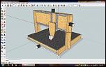
The most recent itertaion. Using most if not all of the recomendations gathered here.

The Table travel is only out from this point to keep it from going past the rear extents of the Bottom Torsion Box.
Table Bearings are more centered in both X and Y.
Both X and Z cars are now "boxed" with the bearings nested in each car.
Gantry is fully boxed and will have internal gusetts for added rigidity.
-
03-20-2013, 03:16 AM #15
Registered
- Join Date
- Mar 2013
- Posts
- 81
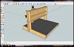
And here it is cleaned up a bit.

-
03-21-2013, 06:45 AM #16
Registered
- Join Date
- Aug 2011
- Posts
- 388
Nice improvements! Those reinforcements will help stiffness a great deal. I was thinking of a different type of 'nesting', but I like your interpretation and it's cleaner.
Some more suggestions, if of interest...
- The gantry tube appears vulnerable at its joint to the boxed sides. Perhaps increase the depth of the gantry tube by 3x - 4x -- that would increase its own stiffness a lot, and give it a stronger and stiffer connection to the base.
- If you want a bit more z clearance, that deeper gantry tube should be plenty stiff to enable that.
- Ideally, the upper and lower Z bearings feed their loads ~directly into the upper and lower X rails -- that minimizes flex in the X car. For cutting sheets just above the table, the matchup usually works out well when the Z bearing vertical spacing is similar to or a little less than the X rail vertical spacing. So I'd increase the z bearing vertical spacing some (with longer z rails for the same travel).David Malicky
-
03-21-2013, 07:47 AM #17
Registered
- Join Date
- Aug 2012
- Posts
- 621
I agree on making the gantry tube wider. Better support/attachment to the risers, and much stiffer to boot. That's shaping up to be a nice strong structure. It'll be pretty heavy, but for a fixed-gantry design, weight is your friend.
Luke"All I'm trying to find out is the fellow's name on first base" -- Lou Costello
-
03-21-2013, 10:33 PM #18
Registered
- Join Date
- Mar 2013
- Posts
- 81
And here are some of the improvements I added.
-
03-21-2013, 11:10 PM #19
Community Moderator
- Join Date
- Mar 2003
- Posts
- 35538
If you haven't purchased your leadscrews yet, make sure you get some that are between 2 and 4 turns per inch, with 2 being a better choice. This will allow you to get the best performance from the motors you have.
Gerry
UCCNC 2017 Screenset
http://www.thecncwoodworker.com/2017.html
Mach3 2010 Screenset
http://www.thecncwoodworker.com/2010.html
JointCAM - CNC Dovetails & Box Joints
http://www.g-forcecnc.com/jointcam.html
(Note: The opinions expressed in this post are my own and are not necessarily those of CNCzone and its management)
-
03-23-2013, 02:09 AM #20
Registered
- Join Date
- Mar 2013
- Posts
- 81
The image tool here is less than perfect.

 Reply With Quote
Similar Threads
-
New Spindle Design, feedback plz!
By h3ndrix in forum Uncategorised MetalWorking MachinesReplies: 95Last Post: 09-22-2014, 09:37 AM -
Joe's 5-axis design feedback
By s3r4ph in forum Joes CNC Model 2006Replies: 18Last Post: 08-27-2012, 11:47 PM -
Feedback on new machine design
By ltovey in forum Australia, New Zealand Club HouseReplies: 5Last Post: 07-16-2011, 06:04 AM -
Need feedback on design
By joeinbend in forum Stepper Motors / DrivesReplies: 0Last Post: 03-01-2010, 08:17 PM -
Need feedback on design.
By Mike F in forum DIY CNC Router Table MachinesReplies: 19Last Post: 02-13-2004, 02:18 PM
