


Yeah, but I can't send it back and they won't work with me. Apparently its 'hand fitted' although what I saw in you thread makes that comment laughable. I'm done with Grizzly. They wont get another call or order from me. All they're doing is infuriating me and it ruined my day today. So I'm going to find a deal on linear rails and go that route. It's ground fine at the bottom, so it will work fine for most cutting, but it needs to be tight up top for ATC alignment.Originally Posted by 691175002

Thread: Zach's G0704
Results 21 to 40 of 155
-
02-19-2013, 07:10 AM #21
 Registered
- Join Date
- Feb 2013
- Posts
- 164
-
02-19-2013, 07:24 AM #22
Gold Member
- Join Date
- Feb 2006
- Posts
- 7063
When all else fails, write an e-mail directly to the president of the company. You can usually find an e-mail address through Google, or, worst-case, try all the common e-mail formats. I have NEVER failed to get an IMMEDIATE response doing this. Most recently from Comcast, also from Sears, Dell, and others. The response is usually a phone call, within hours, from someone at the Exec level who has the authority to do almost anything. Originally Posted by zamazz
Regards,
Ray L.
-
02-19-2013, 10:56 AM #23
Registered
- Join Date
- May 2009
- Posts
- 36
I would be speaking to them in the manner that the machine in question is not fit for purpose and you will be speaking with trading standards. It is erelevent of what you want to end up doing with the machine (tear it apart, rebuild it etc). You bought the machine in good faith that it was fit for purpose. In most countries the says that you must give them an opertunity to put right the affected part. This is their opertunity to fix the affected part. If they disagree then you will fullfil you end of the bargain by taking the steps further.
Sorry this is my first post and people get me angry when they are trying to kick the underdog.
-
02-26-2013, 05:57 AM #24
Registered
- Join Date
- Feb 2013
- Posts
- 164
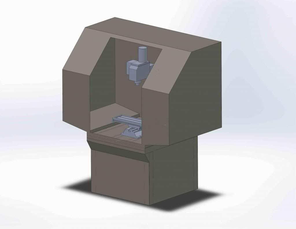
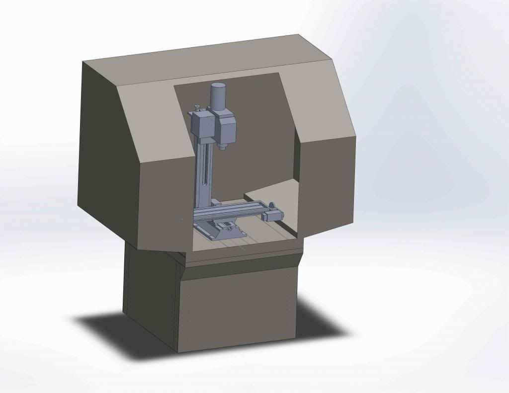
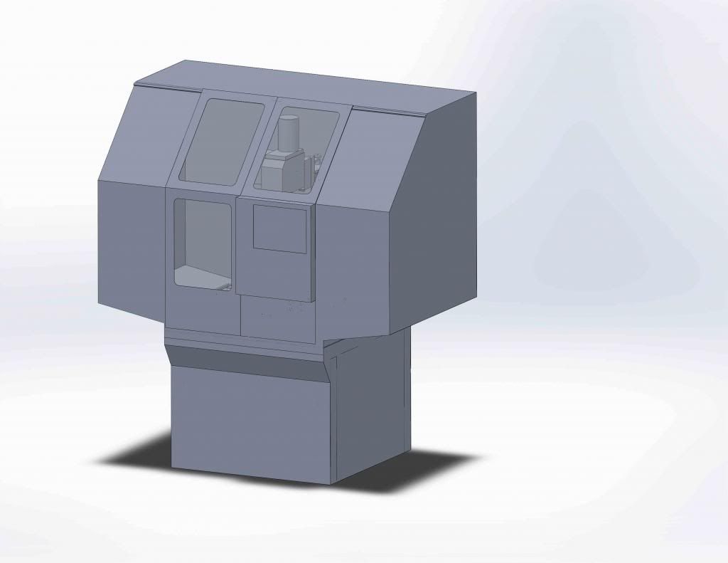
Well, here's a little preview of the mill. The only problem I foresee is that the enclosure and stand weigh about 250 lbs. That's without electronics, computer, mill, casters, wiring, vise(s), coolant system, new motor and drawbar, eventual ATC, and some internal enclosure structure. This thing is getting less portable every time I open Solidworks! It's looking like 1000 lbs, or better, assembled.
Sorry for the hasty screenshots, I'll do some actual rendering once I finish the design.
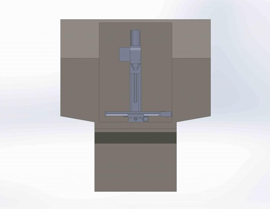
I got a pretty good price on an Elo touchscreen, so that will be placed in one of the doors (yet to be drawn), as well as all the other controls. Originally I wanted a flip up door, but reconsidered due to low ceilings and monitor mounting issues. I'm now contemplating dual sliding doors. Also, I'd like to fill the main frame with sand, to deaden vibrations, as well as triangulate wherever possible to add further rigidity. I've been waiting for Paypal to clear some funds, then the build will be back in action!
-
02-26-2013, 06:57 AM #25
Registered
- Join Date
- Feb 2013
- Posts
- 164
Also, I sent an email (well more of a novel) to Grizzly's president. I'm unsure if I used his correct email, so if anyone knows it I would appreciate confirmation.
-
02-26-2013, 11:04 AM #26
Registered
- Join Date
- Nov 2007
- Posts
- 980
I love the look of the enclosure, but just be sure you can fit inside of it (or the panels are easily removed) as you'll want to get in there for something in the future, I can almost guarantee it. From the drawing it looks like the opening may be a little tight for you to fit in the reach the back for something, at the very least, just general cleaning.
Just a thought for you,
DaveDave->..
-
02-26-2013, 07:28 PM #27
Registered
- Join Date
- Feb 2013
- Posts
- 164
Thanks for the advice, Ray. I did exactly that, and got a phone call from the general manager within 10 hours. Apparently they will be sending three matched replacement parts to fix the problem (column, Z carriage, and head? Or possibly the Z nut.) So I may not use linears, after all. Originally Posted by HimyKabibble
I do intend to make the whole top enclosure removable, although it won't be particularly easy. Also, I would like side panels to be removable. Once again, I'm still working out the fine details.
-
02-27-2013, 06:18 AM #28
Registered
- Join Date
- Feb 2013
- Posts
- 164
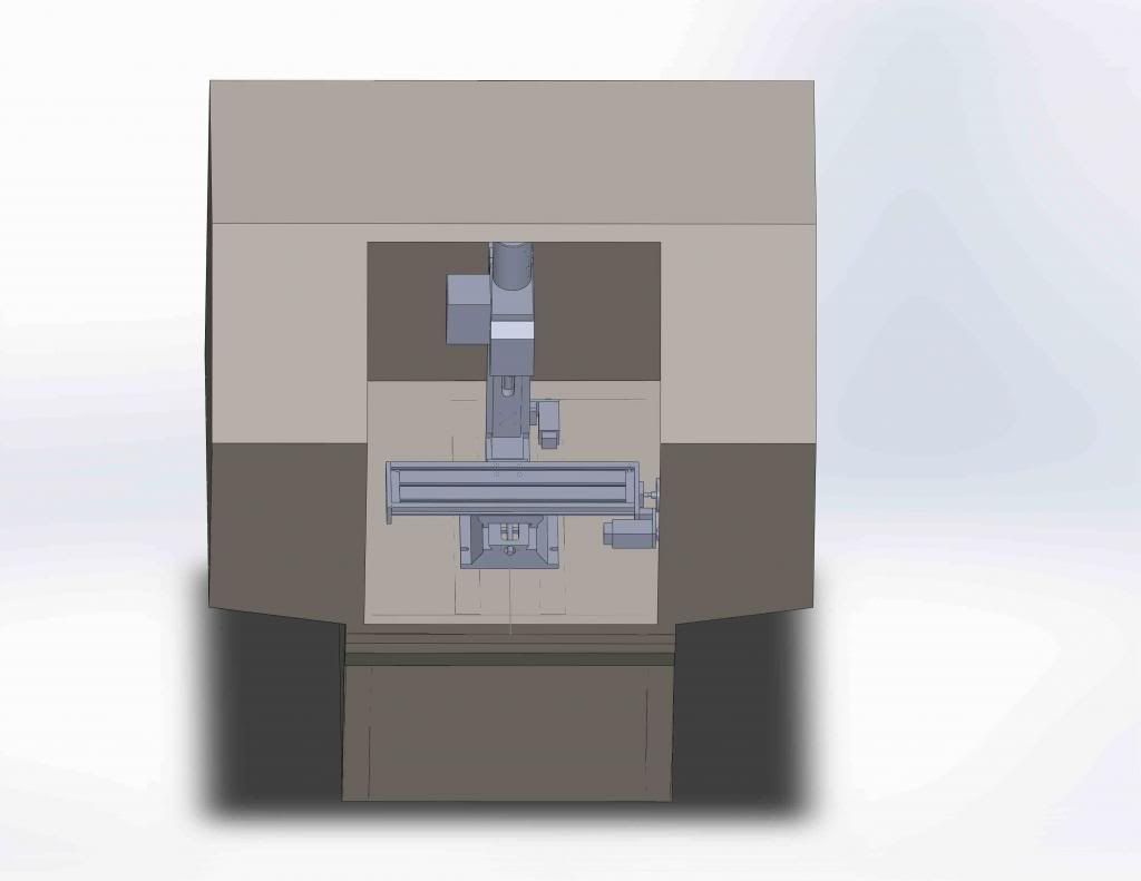
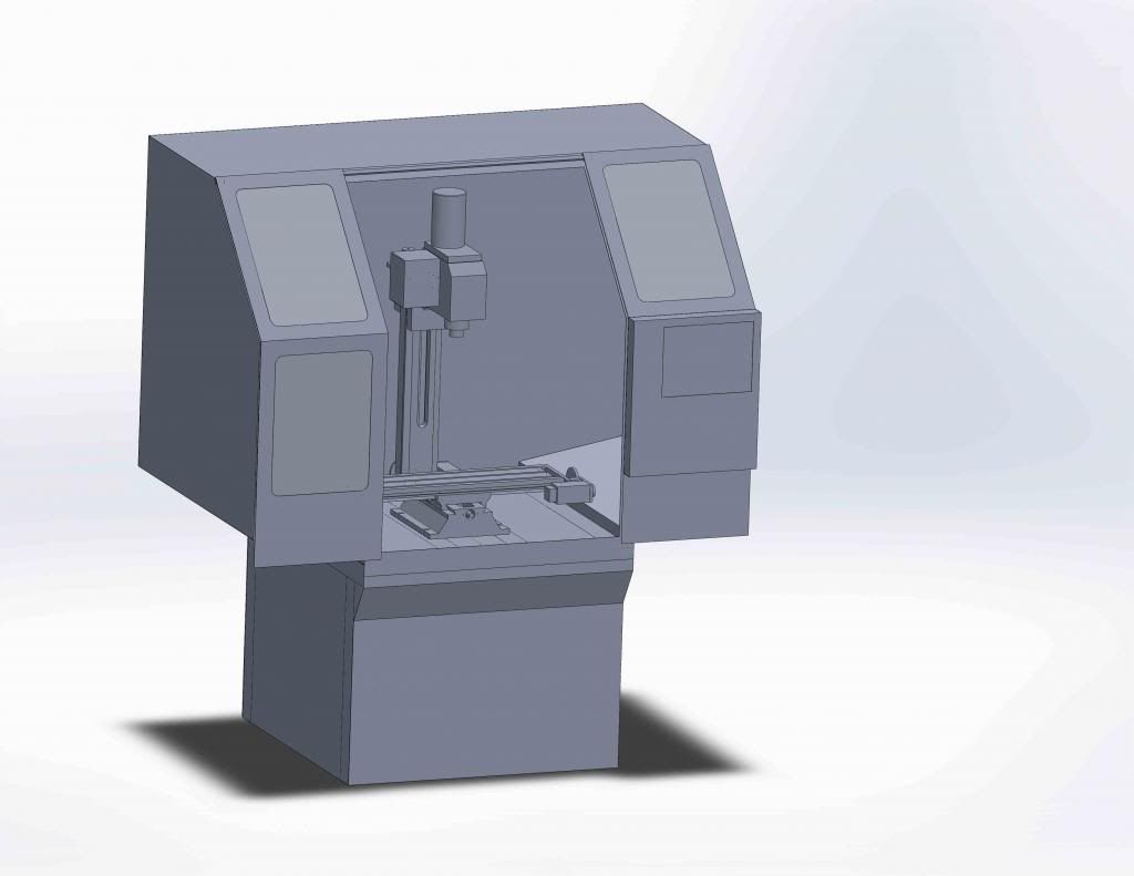
And doors! The model is almost entirely complete, barring the ATC and some minor internal structure for the enclosure. The doors will ride on 4 drawer slides, I'll probably also add handles and a latch of some type and perhaps a safety switch that will stop the machine from starting if the doors are open or sound an alarm. This will, of course, need to be an override, as I may need the doors open at times. Everything is drawn with 22 gauge steel, but this may dent too easy for some of the larger pieces. I will probably use 20 instead. This enclosure might test my fabrication skills, but I'm always down for a challenge!
The box on the door will house the touchscreen monitor, keyboard, e-stop, various buttons and switches, and USB ports. The computer and the bulk of the electronics will be in the lower part of the enclosure, as will the coolant reservoir. I'll connect them with drag chain to the door.
Some actual progress will be coming here in a week, not just the virtual stuff, after I get some pesky tests over with.
Also, sorry... I'm not terribly good at centering drawings when taking snapshots...
-
02-27-2013, 01:49 PM #29
Registered
- Join Date
- Feb 2012
- Posts
- 296
Looks good!
As for the centering, in your CAD program there should be a button that says something like "fit to screen" so just set the orientation of the model and click that button and it should be centered.
Also, why the decision to put the main control panel on the door? IMO that takes up valuable window real estate which is important so that you can see what the machine is doing in case you need to E-stop. Also, you have to worry about how you are going to route all the cables for signals, power, and grounding...seems like it is too much trouble for no gain.
I am looking forward to seeing how you do your ATC.
Good luck.
-
02-27-2013, 02:04 PM #30
Registered
- Join Date
- Mar 2012
- Posts
- 231
Glad to see that it looks like you have your issues resolved with Grizzly, it's a shame you had to jump through hoops. They should know better, a couple of bad experiences from poster's in these type forums, and sales will fall off.
Are you concerned at all about putting the computer equipment under the enclosure? There's going to be tons of coolant above, any leaks would not be a happy situation.... Just thinking out loud.....
CR
-
02-27-2013, 05:36 PM #31
Registered
- Join Date
- Feb 2013
- Posts
- 164
If I use Solidworks centering feature, it centers to the 16:9 aspect ratio of my monitor. The snapshots are 3:4, chopping off the right hand side of the image. If I were to use the actual rendering feature (instead of 'save as jpeg') it would fix the problem, but I've yet to define materials and colors. Originally Posted by DRock
The main reason I put it in the door is it's out of the way. With the doors sliding sideways, there is no frontal space that isn't moving to put the monitor. It's too tall to put it on top (the mill is enclosed for sound reasons), and there isn't much room to the sides for a monitor arm. So either I put it in one of the doors, or it sits off the machine somewhere, and I'd rather have a consolidated package.
Originally Posted by ny_racer_xxx
Yes, this is one of my concerns. I plan to seal the chip pan and coolant system as well as sealing the electronics box. I'm sure the mill will leak somewhere, but sealing the electronics as well should keep them safe. I'll have to vent them downward, so gravity can't push anything past the fans.
-
03-01-2013, 06:55 AM #32
Registered
- Join Date
- Feb 2013
- Posts
- 164
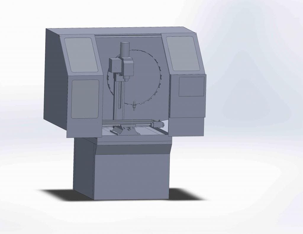
Started the ATC. I had this idea the other night, to rotate the ATC 90 degrees and put it against the back wall, but now I'm starting to rethink. There are advantages and disadvantages. The pros are that it will allow a large number of tools without getting in the way of anything. Because it doesn't sit over the table, I don't have to worry about interference. Additionally, shielding the tools from swarf will be easy; I'll just place a piece of Plexiglass in front of the changer. Half of the shield can swing out of the way to facilitate tool loading.
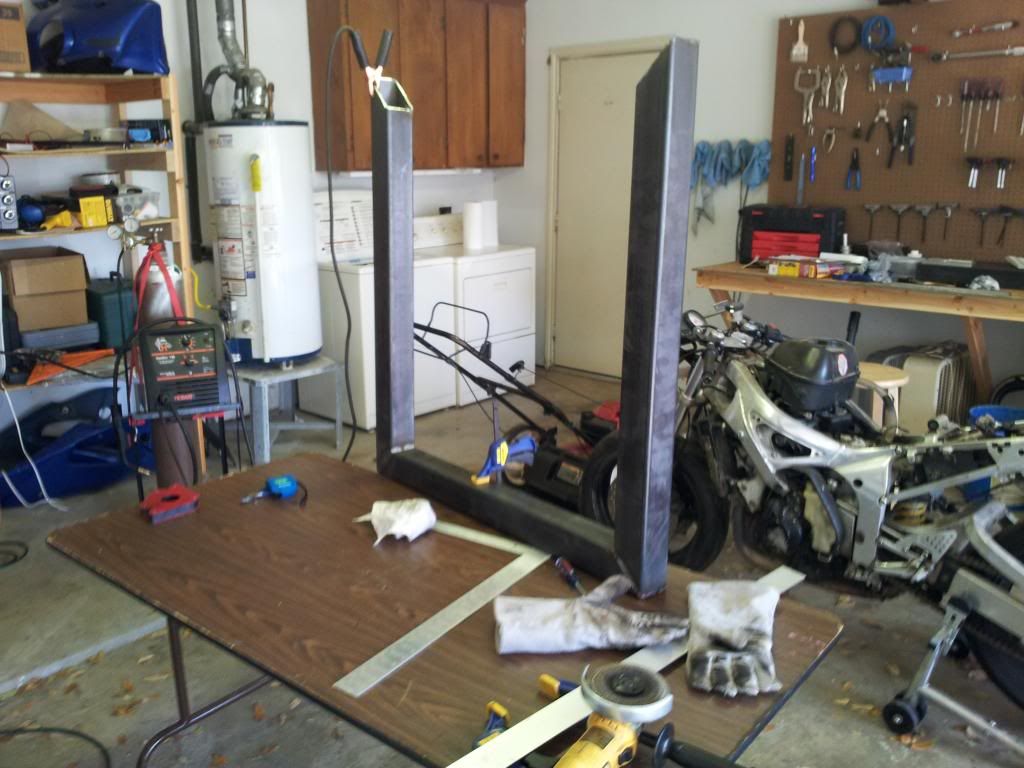
It will require a loading arm to rotate the tool to the spindle, which isn't a problem at all. What I don't like is that the loading arm will also have to move vertically to get the tool to an appropriate height. Once again, I don't foresee this being an issue, but it does require an air cylinder, bringing the count to two stepper/servo motors and two air cylinders. I/O won't be a problem on the Mesa board, but I'd like to keep it simple and rigid, lessening the chance of misloads. Additionally, It will be a long reach to load tools that far back in the enclosure, however I probably won't be switching tools all that often. It's currently drawn for 20 tools, but I could probably get up to 30-36 without increasing the diameter of the wheel. The biggest thing would be swapping drill sizes.
Shown is a really rough sketch, void of the arm and motor mechanisms. Thoughts?
-
03-02-2013, 05:56 AM #33
Registered
- Join Date
- Feb 2013
- Posts
- 164
Well, I bought the materials for the stand, about $150 of steel, but it doesn't look like I'll be able to do anything this weekend. The season opener for motorcycle racing is tomorrow, and I think I'd rather be there! However:
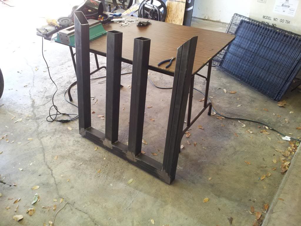
I got 30' of 3"x3"x.125" square tubing and some 1" square for bracing, which should be plenty to build the lower stand. I'll add some triangulation later, and fill with sand. Spring break is in a weeks, so look for a bunch of progress!
Also, I received a package from Grizzly today. They sent and entire mated column assembly, including all the unnecessary parts, but it looks properly made. This should get the build back on track!
-
03-02-2013, 12:27 PM #34
Registered
- Join Date
- Nov 2007
- Posts
- 980
That's just excellent to hear, glad they came through for you.

How will they handle sending the old parts back to them?
DaveDave->..
-
03-20-2013, 03:37 AM #35
Registered
- Join Date
- Jul 2010
- Posts
- 152
Zamazz,
Everything is coming along nicely. Any more updates?
I have a comment about the doors of your enclosure. I would suggest putting the doors on the inside of the enclosure rather then outside like you're currently planning.
For one, it will be easier to contain liquids/swarf especially if your doors are just a little wider then the opening and secondly, you can mount the screen and electronics to the side of the enclosure rather then the sliding door which should simplify mounting.
adrian.adrian.
-
03-20-2013, 04:33 AM #36
Registered
- Join Date
- Feb 2013
- Posts
- 164
I've been working on the mill, I'm just finding it hard to get to the computer and type up an update. The doors on the inside is a very good idea I never thought of. It wouldn't be anymore difficult to build, but, as you said, would make electronic mounting far easier. I may just change the design over to that. I've already got 16" drawer slides on hand that lock closed, so I was planning on using two for each door so that one is always extended while the other is closed. This way, the door will lock in both the open and closed position. I may have to do some resizing to get the doors to work properly on the inside, but it does seem a more attractive idea. Anyway, for an update... Originally Posted by outsider787
Although I didn't get any pictures, I finished up a majority of the X axis, including ballscrew machining, the end-plates, and the servo mounting brackets. I fit everything nicely to the A/C bearings I had on hand. The machine shop I'm building it in is an hour away, which limits me to weekends mostly. Knowing that, I tried to completely machine the X axis so I could play with it during the week. Naturally, I forgot one thing: to cut down the ballnut. So tonight when I started assembling it, I didn't get very far Oh well, I'll just have to wait till this coming weekend. I also received all the ballscrews and nuts from Chai, unmachined, with dual nuts on all axes. Additionally, there is a box from coming from Canada sometime this week with a pretty penny worth of motors. I opted for 300W's on the X&Y and 400W on the Z. I also got their proximity limit switches, as they were cheaper than I could get them elsewhere. There will be 6 limit/homing switches on the machine, all non contact NPN proximity sensors.
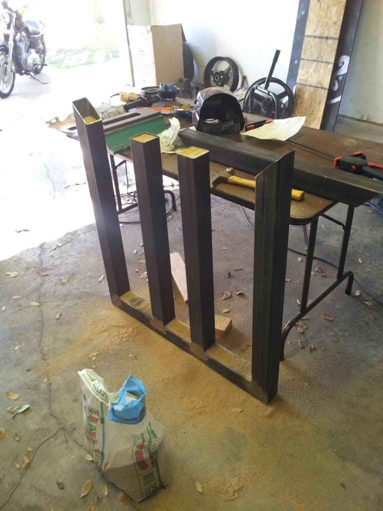
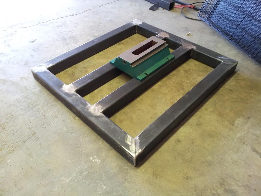
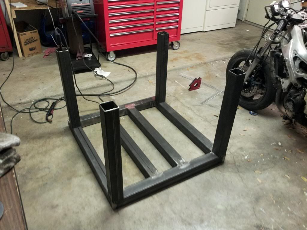
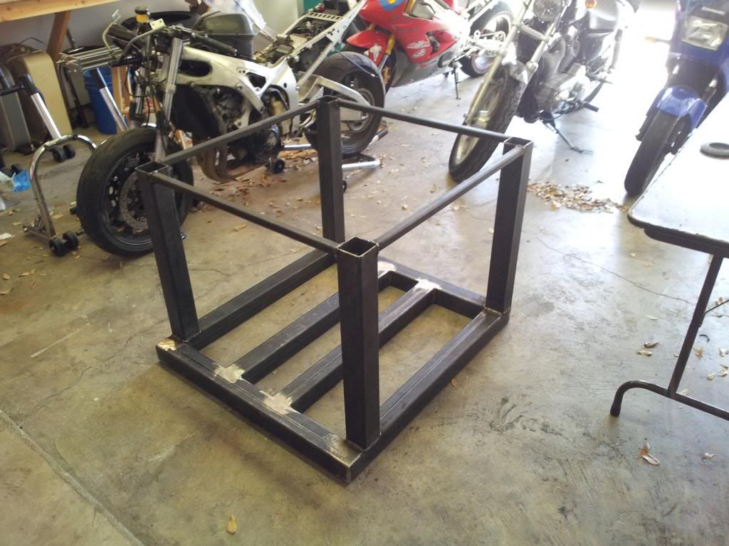
In other news, I started on the enclosure. With around $150 worth of 3" by .125 square tubing, I started welding up the base for the machine. I started by cutting all the angles (which is really a PITA when you only have an angle grinder), then welded up the 3 sides of the outer table. I took extra care to get everything level and used clamps to prevent warping (as much as possible).
From here I welded in the bars that the machine sits on, still leaving one side open.
The reason for welding in this order was this:
I sand filled the entire frame at this point, filling all three sides and the two cross supports all the way to the top. It was about a bag and a half of sand, or 75 lbs (34 kg for all you foreigners. As an engineer I envy those of you who use the metric system). Then I welded on the top section, obviously empty. The sand in the other 3 sections will be free to move in there, which should fill to about 75%. This should be plenty of sand, whacking the frame with a hammer results in a dull thud, no ringing like I got before the sand. For those of you wondering, this is also a great way to turn your garage into a sandbox.
When she was all done and cleaned up I put the base on there for scale purposes. Everything is easily within 1/8" flatness, with the two rails for the machine very parallel to one another. I'm sure I'll have to shim the base some, or possibly use a leveling epoxy to get it perfectly flat. Note that this was very much stuck in this position on the ground until I got help moving it. With the sand it is over 150 lbs, according to solidworks and the amount of sand I poured. That's more than I can move!
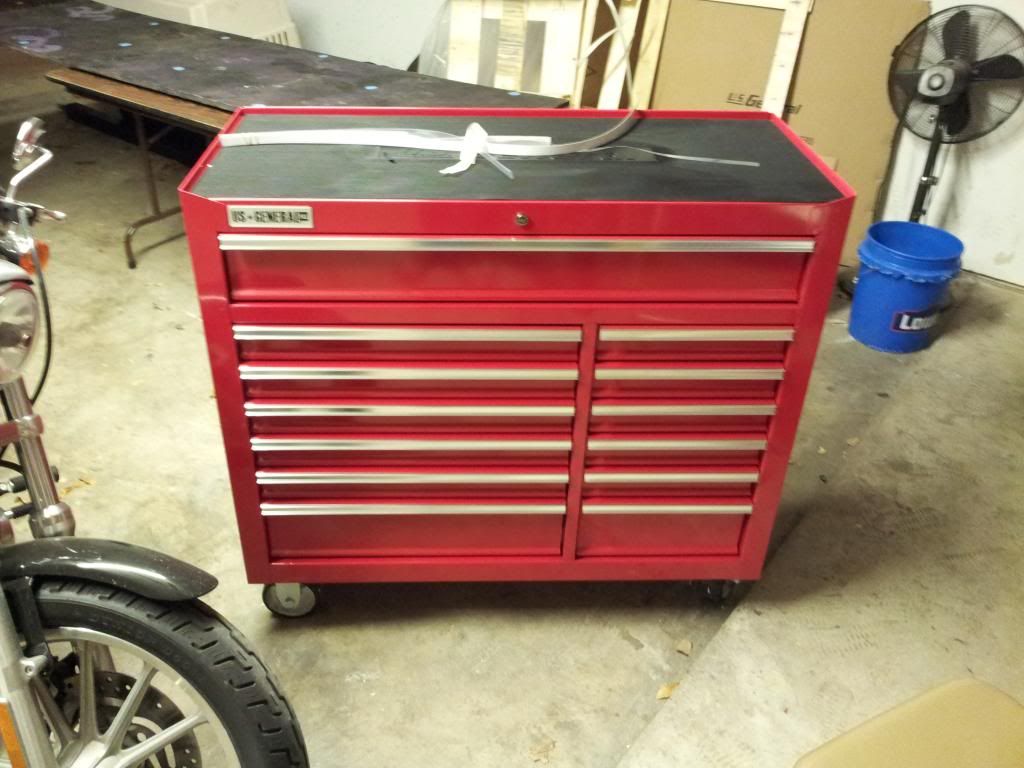
Sorry for the poor picture, but I also treated myself to another new toy. The quality seems really good, despite coming from Harbor Freight. In the crate it weighs 305 lbs, and took four people to get out of my truck, so it is built fairly heftily. Its has great reviews and can hold almost 3000 lbs of tools, which is far more than I have. I've currently got my surface plate on it and all of my measuring equipment in the top drawer. It will hopefully become a mobile inspection/QC station once I get my mill running.
-
03-20-2013, 01:19 PM #37
Registered
- Join Date
- Jul 2010
- Posts
- 152
Good stuff.
One other note on the sliding doors. When the sliders are fully extended, they will collect stuff (swarf) in their track and possibly jam themselves.
I ended up changing the design of my doors so that the drawer sliders are hidden behind the door itself when the door is closed. That means the sliders are fully retracted when the door is closed and avoiding any possibility of getting anything stuck in their track.
I wouldn't worry too much about the door locking in the open position. The doors will spend the majority of their life in the closed position so as long as you have the sliders loch on that position, you should be good.
This is all advice I got from others when I built my enclosure, and has helped me. Hope it gives you something to think about.
adrian.adrian.
-
03-20-2013, 06:12 PM #38
Registered
- Join Date
- Nov 2011
- Posts
- 205
Call me skewed, but i did it anyway.
I deliberately made the stand so that the fluid would collect at the drain. Then I made some aluminum blocks and rubber washers siliconed to seal them. The blocks were custom fitted to level the mill.
Don
--
-
03-20-2013, 08:56 PM #39
Registered
- Join Date
- Oct 2012
- Posts
- 23
I will be following this build to see what works, great job, keep it up!
-
03-26-2013, 05:05 AM #40
Registered
- Join Date
- Feb 2013
- Posts
- 164
Yes, I'm looking forward the seeing what works as well. I've built too many automated systems to expect everything to work the first try. I spent 16 hours on my most recent one trying to get one stupid little piece of plastic to drop out of a hopper without jamming and faulting the machine... Everything here seems relatively straight forward, but that doesn't mean there won't be a fair share of issues. I've found a few already... Originally Posted by etard
The issues: For one, I bought a ballscrew a couple months ago, since it was a very good price. It was a 1605, but from a different seller on ebay (not Chai), although it looked identical. The rest of my ballscrews were sourced from Chai, as well as an extra nut to go with the first ballscrew. The initial ballscrew was great, even better than those from Chai, fit and finish-wise. However, when I try to get the nut from Chai on the other ballscrew, it simply will not go. I calipered the minor diameter of the screw and got a .017" difference between the two! Now, since this is a second ballnut, purely for preloading purposes, I figured I'd just repack the nut with much smaller balls and not worry if there was a little backlash. For the price of two sizes balls, however, I can get another nut, although it will take awhile to arrive from china, and it may have the same problem. If I knew smaller balls would work, I'd have no problem ordering them rather than another nut. I did measure the balls out of Chai's ballscrews, and they were exactly .125. The smallest balls I could find were .1237, which doesn't sound small enough when the difference in screw sizes is .017. Thoughts?
Also, when I engineered the mounts I used the dimensions on ebay, which led some issues. The main one is that I used M6 screws to mount the 1605 ballnuts to all the holders, and they are about .015 bigger than the holes in the ballnuts. Since the nuts are case hardened, I'm having a hard time opening them up. Ideally I'd just get a carbide drill, but I can't find one locally and probably don't want to see the price if I could. My current thought is to use a dremel and widen the holes, or a die grinder with a 1/4 grinding bit and plunge it through the hole. I'll see how that works out in the next couple days.
The servos are on their way. I can hardly contain myself I'm so excited. I've been checking tracking every hour, which is totally useless since it just says "Usa others" for the destination. I guess that's what you get when you order from Canada, eh?
Also, I'm very close to finishing the base. I attached the legs, I'm just waiting on some 1/8 x 3" plate to cap the legs (after sand fill) and I'll attach the leveling coaster, which I already have. I have to be careful attaching things, since I cant just drill and tap into the frame. I don't want to lose any sand...
Most of the welding turned out very nice (although I do wish I had the TIG I use at work instead of my little MIG). Some of the really short beads got a little wobbly... Its hard to weld upside down under a shower of sparks. The thing was way to heavy to flip over to get a better angle. I intend to add a bit of triangulation to certain areas with some left over scraps, although I wonder I should even bother. For one, I won't be able to fill with sand, and secondly, this thing is built. Using Solidworks FEA (I know, not the best, but certainly the fastest) I got a displacement of under 2 mm max for a 4000 lb force on the two cross bars and a stress factor of safety of 1.5ish. Of course, the welds will likely snap before that, but the point is it is way overbuilt.

 Reply With Quote
Similar Threads
-
DRO for G0704
By UMR in forum Benchtop MachinesReplies: 4Last Post: 07-06-2016, 04:04 AM -
No Joy with my New G0704
By DogWood in forum Benchtop MachinesReplies: 5Last Post: 07-05-2016, 05:49 PM -
Zach's Homebrew CNC Mill
By Zach_G in forum Vertical Mill, Lathe Project LogReplies: 76Last Post: 06-27-2015, 04:28 AM -
G0704... Yes Another One ;)
By ww_kayak in forum Benchtop MachinesReplies: 24Last Post: 05-27-2013, 03:47 PM -
G0704 or a X-3
By USN in forum Benchtop MachinesReplies: 8Last Post: 05-30-2011, 08:24 AM
