


Thanks for the reply rwskinnerOriginally Posted by rwskinner

I had thought about the point you brought up with the surfaces not being parallel, but it was after the mounts for the pillow blocks had already been made. I wish I had designed in set screws, so I could dial everything in--hopefully everything plays nice once I put it together. I over sized the holes on the blocks that attach to the x and y axis so hopefully I can account for some of the miss alignment--not sure though. I think the x-axis will be the most problematic since it is secured at both ends.
Thread: Graham's Optimum BF20 Build
Results 41 to 60 of 192
-
09-16-2013, 02:00 AM #41
 Registered
- Join Date
- Nov 2012
- Posts
- 220
-
09-16-2013, 03:19 AM #42
Registered
- Join Date
- Nov 2012
- Posts
- 220
So, today I was trying to put some threads on the floating end on my ball screw using a die. Turns out the ball screw was really brittle and didn't take to the die very well. I was able to cut the threads but they were rough and when I put a locknut on the end the threads broke off

This leads me to my next question...Is it possible to use Rex ball nuts with Linear Motion ball screws? This would save me money, because I would not have to get them machined locally. If I can, I am guessing I would need to resize the balls in the ball nuts?
Any feedback would be great
Thanks
Graham
-
09-22-2013, 03:07 AM #43
Registered
- Join Date
- Nov 2012
- Posts
- 220
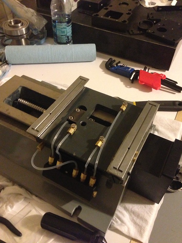
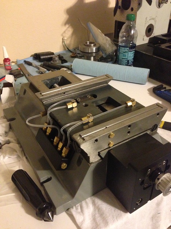
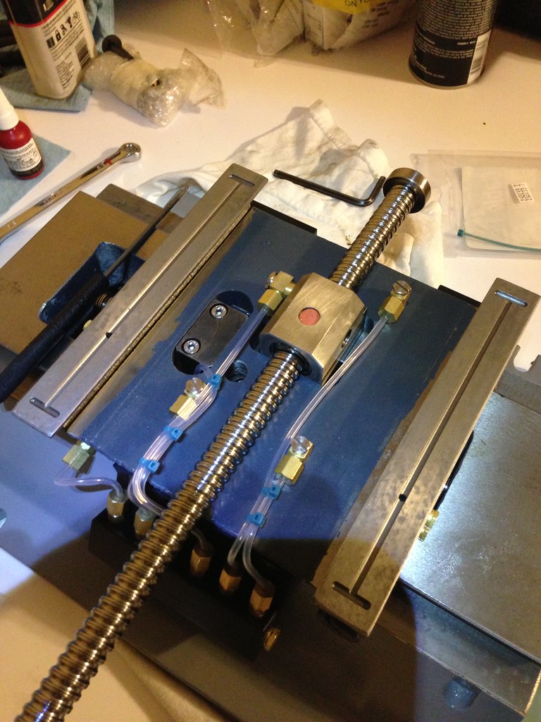
I have been test fitting parts and working towards getting everything assembled. While I was doing that I managed to dump the balls out of one of my ball nuts. It turned out to be a good thing. I learned how to repack a ball nut (not as hard as I thought) and I got to clean it out. I am not sure why but the vendor did not completely fill the nut with balls, so I ordered some extra off of ebay and I am going to clean and repack my other two ball nuts. One other thing I did was drill a 5/16” hole in my y-axis gib for an oil passage (Thank you Hoss). I think I am going to need to make the hole a slot. When I installed and marked the gib for the hole I drilled, I used oil, but when I reinstalled it I used grease. For some reason everything fits tighter with grease and now the hole does not line up as well as I would like with the oil inlet. Here are pictures from the silliness.
Mounting pillow block to ball screw:
Attachment 201730
Mounting first y-axis part:
Attachment 201732 Attachment 201734
Mounting second y-axis part:
Attachment 201736 Attachment 201738
Gib with 5/16" drilled hole:
Attachment 201740
Saddle mounted:
Attachment 201742 Attachment 201744
Oh, after the groves were machined in the saddle I had to come back and take a razor to the edges of the groves to take the edge off of them; they were shaving material off of the ways.
-
09-22-2013, 07:53 PM #44
Member
- Join Date
- Oct 2008
- Posts
- 1632
I took a ball mill and machined a groove on the inside of the gibs so they could be adjusted in and out and the oil still had a passage to the thru hole. Just It doesn't have to very deep or very long. I think mine was 1/2" before and 1" after the hole so that means I could tighten the gib up to an inch more and the oil would still pass. Anymore than that I would be out of gib adjustment anyways.
Richard
-
09-23-2013, 01:37 AM #45
Registered
- Join Date
- Nov 2012
- Posts
- 220
That is a smart way of doing it, thank you. Originally Posted by rwskinner
-
10-14-2013, 02:21 AM #46
Registered
- Join Date
- Nov 2012
- Posts
- 220
Plugging Along
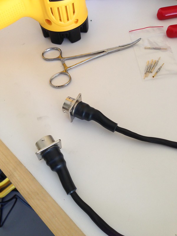
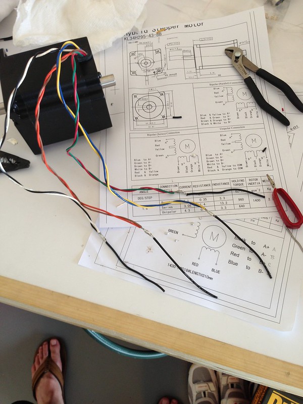
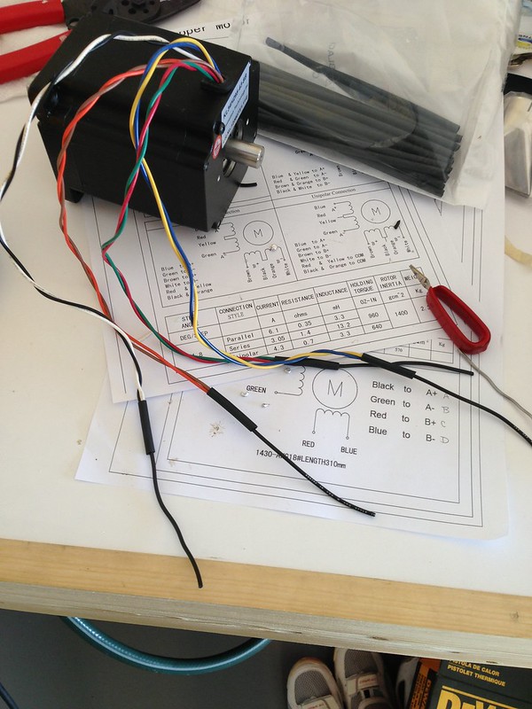
I am out of town right now but the last couple of weeks I connectorized my stepper motors, painted the mill base and column, and mounted my new electronics enclosure.
I bought the connectors off of McMaster. The pins crimp on the wires, so not sure I would recommend these unless you have access to a crimper, which run around $168 or you could always solder them. I wish I had not of run the heat shrink so far up the wires because now they are stiff and also putting some nylon sleeving over the loose wires would have been a good idea.
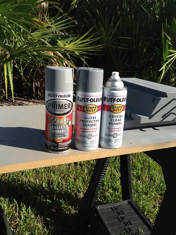
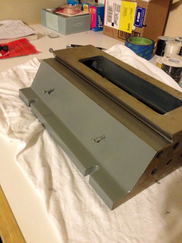
Painting the column and base went way better than I expected. The Rust-Oleum primer with body filler sanded really well and let me smooth everything out. I used a total of two cans of primer for the column and base. I used one can each of gray and clear coat for the column and base. I am not sure how the paint will hold up to the cutting fluid but right now it looks pretty good
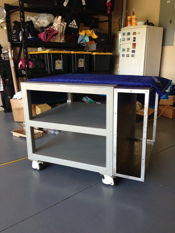
I had a new enclosure made which turned out to be cheaper than the Hoffman box I bought. This will give me all the expandability I will need. The other reason I had a new box made was because I dicked-up the old box trying to punch all the holes in it I needed. On the new box I made the front and rear panel removable so I can update them easily and everything will mount on din rails.
Connectorizing the nema 23 motors:
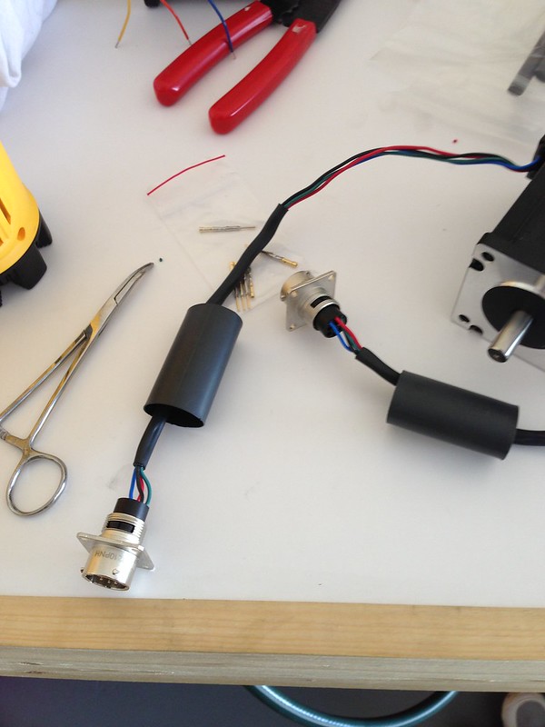
Sealing the connectors against water with heat shrink:
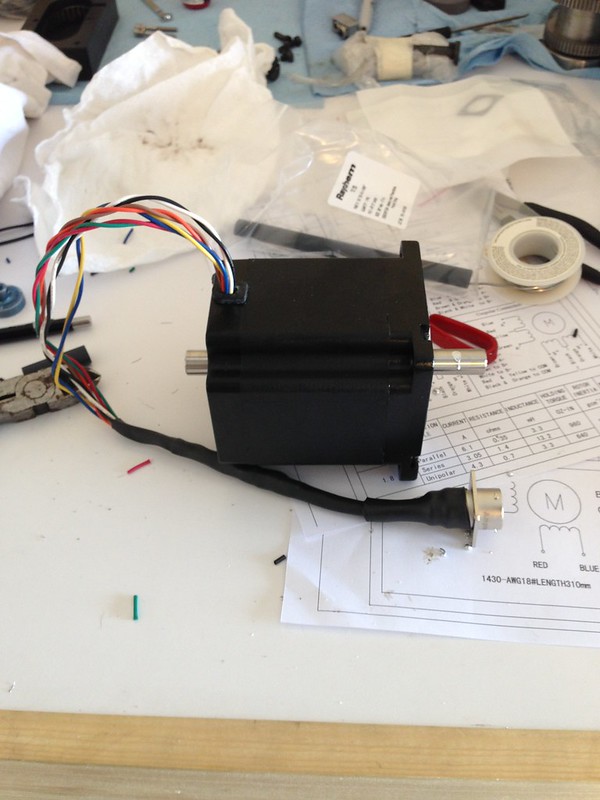
Connectorizing the nema 34 motor:
Priming the base and column:
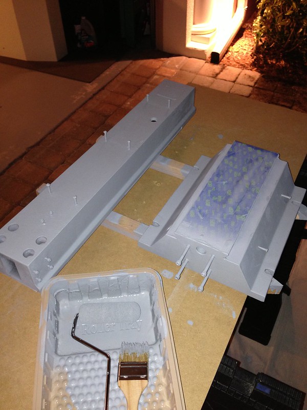
Final Coat:
Match drilling the new control box:
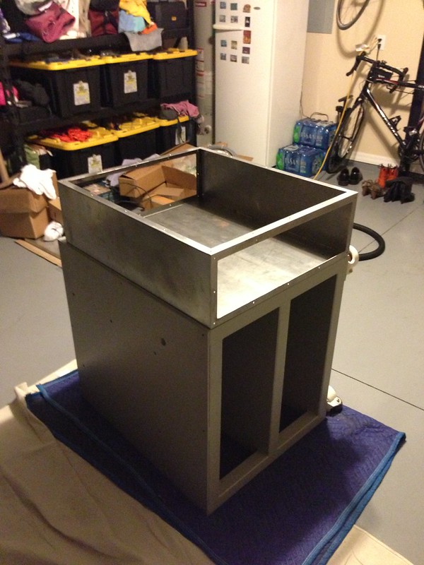
Control box mounted:
When I get back I am going to get the enclosure powder coated, chem film the electronics panel, and hard anodize all the other parts. Then I will start putting everything together
-
10-17-2013, 10:39 AM #47
Registered
- Join Date
- Oct 2013
- Posts
- 5
nice /1:violin:
-
11-01-2013, 06:12 AM #48
Registered
- Join Date
- Nov 2012
- Posts
- 220
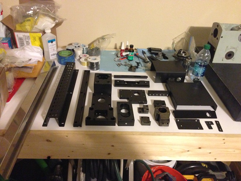
Parts
I thought I would post a picture of most of the parts hard anodized and ready to go. I am going to start putting things together in the morning, but I am still short some stuff I need.
-
11-02-2013, 02:53 AM #49
Registered
- Join Date
- Nov 2012
- Posts
- 220
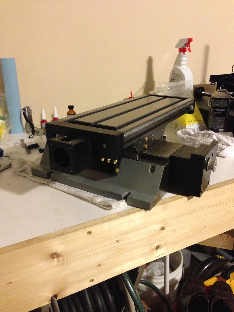
I started running the oil lines on the base. I got the fittings from this company:
Product Catalog | Beswick Engineering
Here are a couple of pics of the mill:
-
11-02-2013, 01:37 PM #50
Registered
- Join Date
- Nov 2007
- Posts
- 980
This is really going to turn out to be beautiful machine, Graham.
You're doing a wonderful job- I'm in awe....
DaveDave->..
-
11-04-2013, 03:11 AM #51
Registered
- Join Date
- Nov 2012
- Posts
- 220
Wow, thanks Dave that is nice to hear. I still have a ways to go, but hopefully everything will turn out. I wish I could get my wife to share your sentiment:cheers: Originally Posted by fretsman
-
12-15-2013, 08:36 PM #52
Registered
- Join Date
- Nov 2012
- Posts
- 220
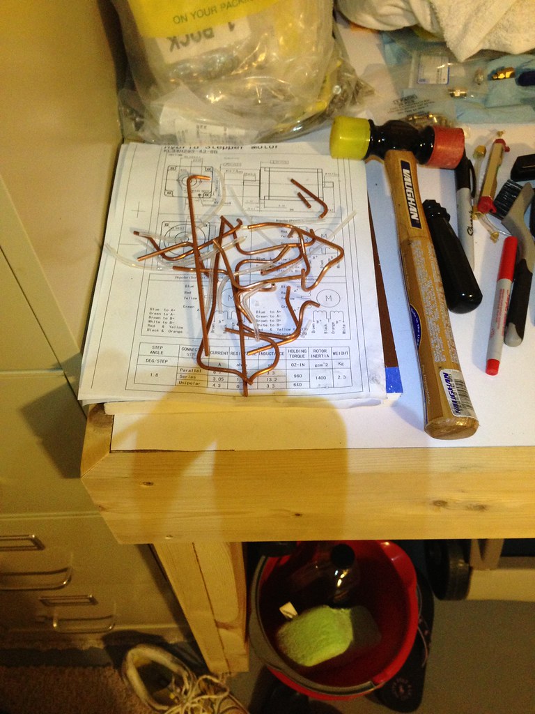
I have been slowly working on the mill while I have been waiting on parts. Initially how I routed my oil lines did not work. When I put the table on it was rubbing on the lines—not a lot of room under that table. So then I got the bright idea to try and run copper lines. I spent about 10 hours and almost 6 feet of copper tubing trying to get it right, but still had problems with the table rubbing on the lines. Mainly the line coming from the y-axis ball nut was the issue. I gave that up and switched back the flexible lines and had everything right in about 3 hours.
Another issue I had was there was too much slop in the x-axis ball nut. This was my fault; I dorked up the old ball screw and had to get a new one, so the ball nut was not fitted to the screw anymore. I fixed it by going from .1246 diameter balls to .1247 diameter balls.
One of the last problems I had was an alignment issue with the y-axis. When I repainted the mill I put a healthy coat of paint on it and this caused the y-axis mount not to sit flat and was making it harder to turn the ball screw when I tightened everything down. It took me a bit to sort it out, but I ended up just sanding all the paint off of the front of the mill. The surface was surprisingly flat underneath with a good finish. Rwskinner’s experience with his X3 was what helped me figure it out.
Finally this is something I am still working on; the table is binding at one end of its travel, so I need to sort that out before I can move on. I have also found some things with the mounts I have designed which I wish I would have done differently. I will fix them later on. All in all though I think everything is coming together.
When I get back from the holidays I should have the rest of my parts in so I will assemble the z-axis and start wiring up and testing the electronics.
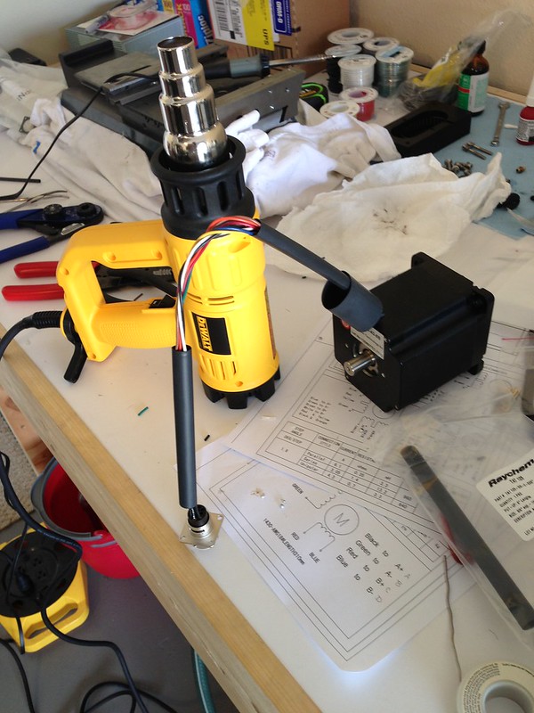
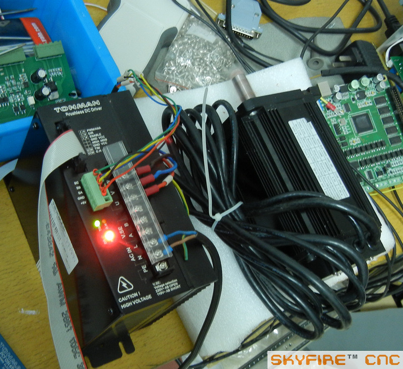
Oh, one last thing, I bought a 1.1KW BLDC motor and driver from Skyfire CNC. There is a picture below of him testing it before he sent it. I have not gotten it yet, but when I do I will post up some more info—pretty excited about it. This should be a good solution for the stock spindle motor and will let me use a regular power draw bar because the motor is not too big. I almost went with a 1.5KW motor, but I did not want to have to change my control box design to accommodate 240 VAC.
X-Axis ball screw in place:
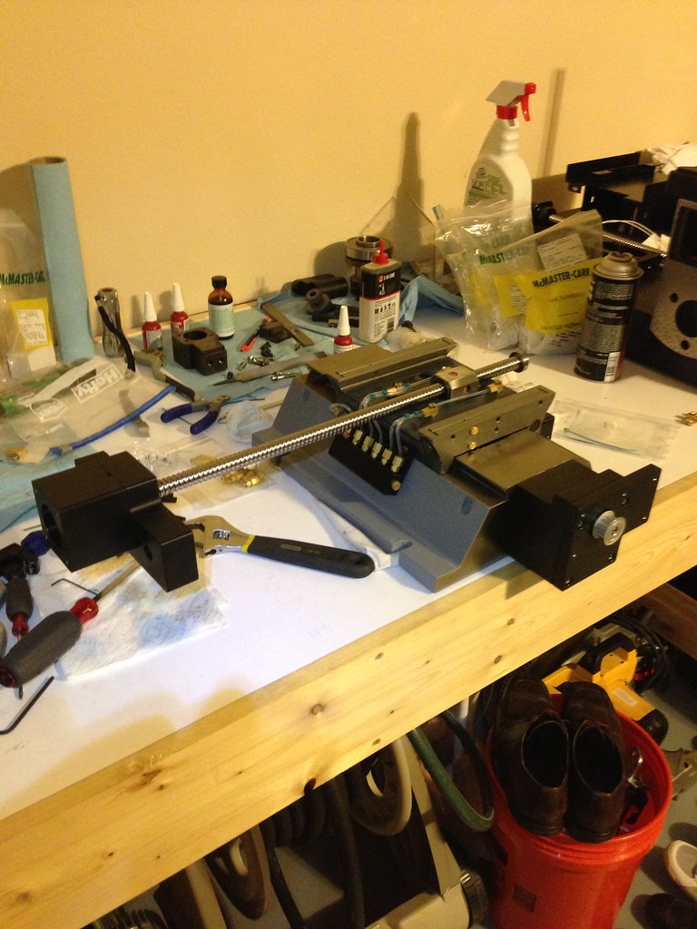
Final oil line routing:
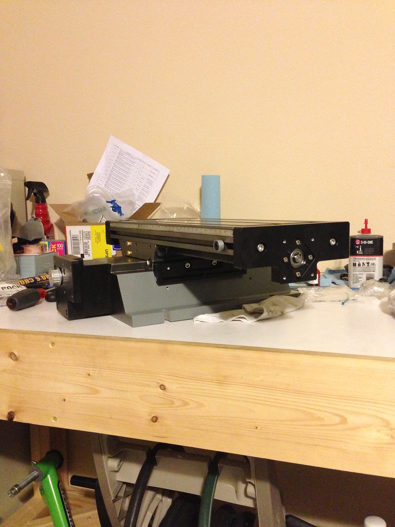
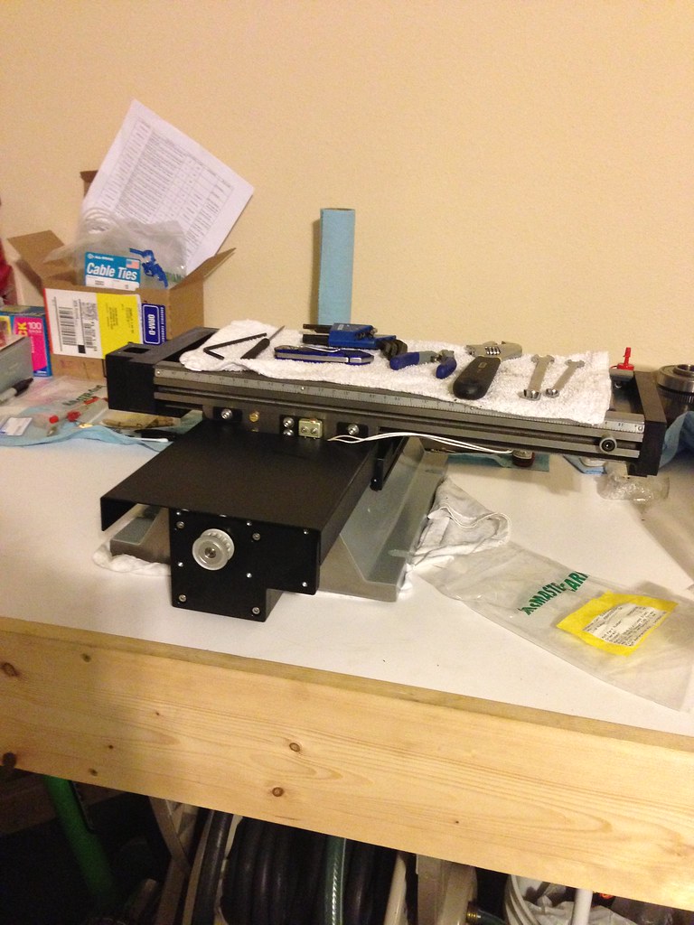
Left side with table on:
Right side with table on:
Front ways cover on and limit switch mounted:
Wasted copper tubing:
New 1.1KW BLDC spindle motor and driver from Skyfirecnc.com:
-
12-17-2013, 02:24 AM #53
Gold Member
- Join Date
- Jun 2011
- Posts
- 695
Nice update! Keep it up.
To bad on the copper tubing....
-
12-25-2013, 07:22 AM #54
Registered
- Join Date
- Nov 2012
- Posts
- 220
Thanks FannBlade Originally Posted by FannBlade
It's ok about the copper tubing. I am glad I tried it. If I hadn't I would have been wishing I had done it.
I am still waiting on parts and about to go out of town for a bit, but when I get back I should be able to get this thing put together.
-
12-25-2013, 10:11 PM #55
Registered
- Join Date
- Nov 2012
- Posts
- 220
Oh, I am sure this is obvious to a lot of you guys, but it was news to me--you can't put power supplies in parallel unless they are designed for it. It wasn't a huge monkey wrench but it did cost me more money.
-
12-27-2013, 03:47 PM #56
Gold Member

- Join Date
- Nov 2009
- Posts
- 4415
Looks great.
-
12-28-2013, 07:51 PM #57
Registered
- Join Date
- Nov 2012
- Posts
- 220
Thanks Fastest1! Originally Posted by Fastest1
-
12-29-2013, 05:00 AM #58
Registered
- Join Date
- Nov 2012
- Posts
- 220
I just wanted to give a quick update (sorry no pictures). I was having trouble with my table sticking at one end of the travel. I took the table off and felt around on the v-groves and the only thing I could find was a tiny nick, so I got a flat file and smoothed it out, put the table back on and tightened everything back up and it worked great. The funny thing is, the nick was in a spot where I would not have thought it made a difference, but it did. I should be getting almost all my part in on Monday, so I will send them out to get anodized. I will start putting the z-axis together after that and testing out the electronics with the steppers connected. Once that is a go, I will mount the steppers to the mill and build all of my cables. I think I will have everything running in two to three months...
-
12-29-2013, 06:03 AM #59
Registered
- Join Date
- Nov 2012
- Posts
- 220
Do any of you guys have wedge nuts you are not using? The ones that go in the front of the table for the x-axis travel limit. Two come with your mill. I need 5 and I have been waiting for months to get them from Grizzly. Send me a PM if you want to sell them to me.
Thanks
-
12-29-2013, 05:23 PM #60
Gold Member
- Join Date
- Nov 2009
- Posts
- 4415
I hate to say it but if it is the part I am thinking of, make it. Originally Posted by gcofieldd
The female threaded piece in the front of the table that is adjustable for a physical stop? Much like a T nut?

 Reply With Quote
Similar Threads
-
my converted optimum bf20 cnc for sale
By 3barboost in forum South Africa Club HouseReplies: 0Last Post: 03-07-2014, 08:39 PM -
Yet another BF20 build by a noob
By crclark in forum Benchtop MachinesReplies: 21Last Post: 02-27-2012, 09:40 PM -
Optimum BF20 G0704 Conversion
By Winnfield in forum Benchtop MachinesReplies: 0Last Post: 08-07-2011, 12:16 AM -
Sieg KX3 or Optimum BF20? Need advice, please.
By anlmat in forum Uncategorised MetalWorking MachinesReplies: 2Last Post: 01-30-2011, 10:21 AM -
BF20 BALLSCREW OPTIMUM
By dfv in forum Uncategorised MetalWorking MachinesReplies: 0Last Post: 04-16-2010, 07:26 PM
