


I am currently building a Linistepper Controller and a Pmino Breakout Board. Excellent designs and I am having a great time putting the boards together. However I was having some trouble with the Breakout Board, which I have not started putting together yet due to my trouble.
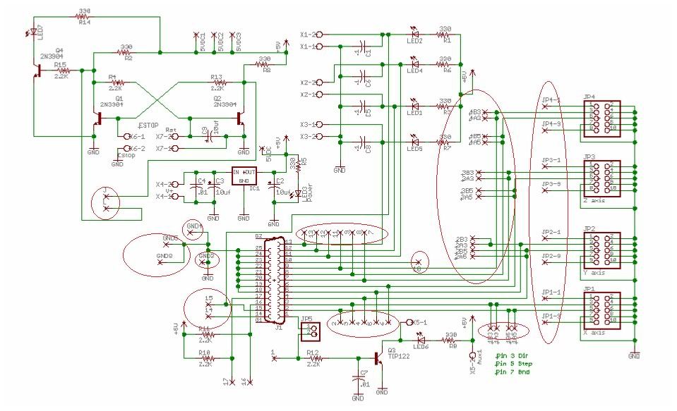
In the diagram graciously provided by Pmino on his website located here I had a question, just one to start with. Should be a quick one. What do the X's on the diagram stand for. Each is labeled but I cannot find anything that corresponds to those labels. I cannot tell if they are simply labels or just label inputs. On the Axis interface the pins labeled 1 and 9 terminate at these X's and this where I am tripped up the most. If anyone can point me in the right direction I would appreciate it. I will include a picture as well with the X's circled.
Thanks for your help.
Here is background info:
I am building my own boards for this machine, not purchasing. The machine will have a roughly 8" X 6" X 4" cutting area and utilize NEMA 17 motors as nothing larger will be required. It is a better solution for this project as it will be used for a completely do it yourself rapid prototyping project that I am producing with a team as a prototype. The final machine will hopefully be taken to local schools to teach seminars or complete courses on rapid prototyping and cnc work. We hope to be teaching future engineering and technology students. The project is completely out of our own pockets and not university funded as of now, though we hope to present it to our professors for possible sponsorship to go at least statewide with it. Any thoughts on this subject are welcome, thanks for looking.
Thread: 4 Axis Breakout Board Help
Results 1 to 3 of 3
-
08-24-2012, 04:10 AM #1
 Registered
- Join Date
- Jul 2012
- Posts
- 23
 4 Axis Breakout Board Help
-
08-24-2012, 05:28 AM #2
Gold Member
- Join Date
- Jan 2010
- Posts
- 2141
It appears to me that those X marks represent header pin test points which may be used to probe the signals with an oscilloscope or logic probe or multimeter, or which also may be used to jumper those circuit locations to other circuit points, either on or off of the board.
If you look at the pdf that you linked to, for example specifically the board layout diagram on page 4 following the heading "Switch Wiring Options", there are individual header pins shown next to each of the 10-pin headers for the 'pminmo standard 10-pin connector' for pins 1 and 9, which are also shown as X marks on your schematic.
And, if you look at the board photo on page 1 of that document, you will see holes (that can accommodate header pins) marked for several of the connections shown with X marks in the schematic.
You can get individual header pins or multiple ones.
-
08-24-2012, 05:17 PM #3
Registered
- Join Date
- Jul 2012
- Posts
- 23
Thank you very much. I believe you are correct. I just needed to be sure. I appreciate you assistance. Going to order my parts tonight. Have a good day.
PurduePete
Sent from my iPhone

 Reply With Quote
Similar Threads
-
5 axis breakout board wiring PLease :'(
By isowe in forum Gecko DrivesReplies: 16Last Post: 08-18-2017, 08:13 PM -
5 Axis Upgraded Breakout board. 2 problems and help required
By Peter Rawlinson in forum CNC Machine Related ElectronicsReplies: 13Last Post: 09-25-2012, 08:15 PM -
Single Axis TB6560 driver and breakout board wiring
By badboy in forum Stepper Motors / DrivesReplies: 5Last Post: 07-10-2012, 11:26 PM -
5 axis breakout board. does the manual show correct pins?
By effimos in forum DIY CNC Router Table MachinesReplies: 11Last Post: 03-30-2012, 08:47 PM
