


Hi everyone!
I've always loved CNC machines, and while I have done a more practical conversion in the past, I've always wanted to convert a mill for fun, without any real goal other than building something awesome. I've chosen to start with a g0704 because it is capable but also fairly small and light.
This build is going to be my pet project for a while and I'll do my best to turn my g0704 into a fully featured and polished cnc conversion.
This is my preliminary todo list for the first stage of my conversion:
- Check the machines accuracy and scrape as necessary
- Double preloaded ballnuts on all axes
- Servos
- Glass Encoders on all axes
- Fourth/Fifth Axis
- Extended Travels
- Automatic Oiler
- Stand that integrates column support
I will be paying special attention to how several of the mods are performed (5th axis, extended travels) to ensure rigidity and accuracy are not compromised.
I am cheating a bit with my buildlog as I started this conversion a few months ago. I didn't have as much time back then and the work was more repetitive though so this just lets me keep the thread interesting.
Anyways, I've been reading about scraping and I picked up a copy of machine tool reconditioning so the first step is to make a straightedge. I am going to have to warn everyone I've never done this before and I really don't know what I am doing. The process seems logical enough though.
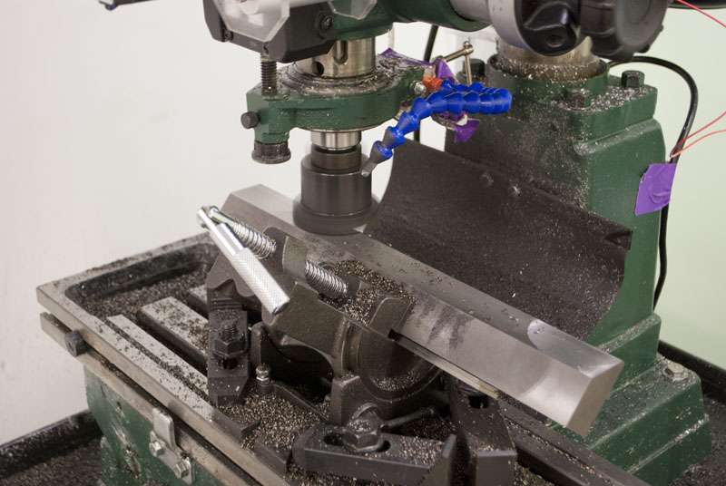
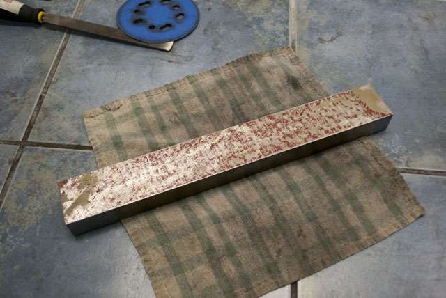
I started with a 2' length of cast iron bar.
Unfortunately, a 16" straightedge was at the absolute limits of my current mills travel and I needed to be very creative to get it cut. Going all the way to the ends of my travel wrecked the accuracy and the surfaces are convex by about 5 thou.
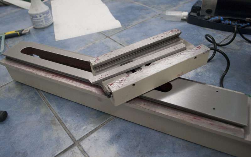
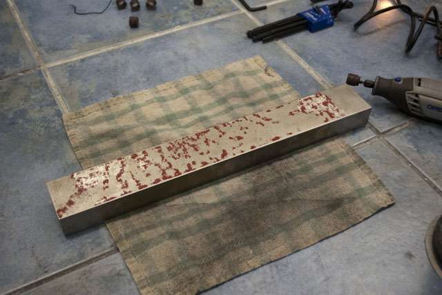
I quickly discovered it would be very tedious to scrape that flat by hand so I cheated and used an orbital sander + dremel to get it somewhat flat.
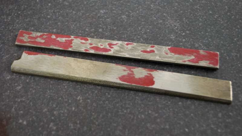
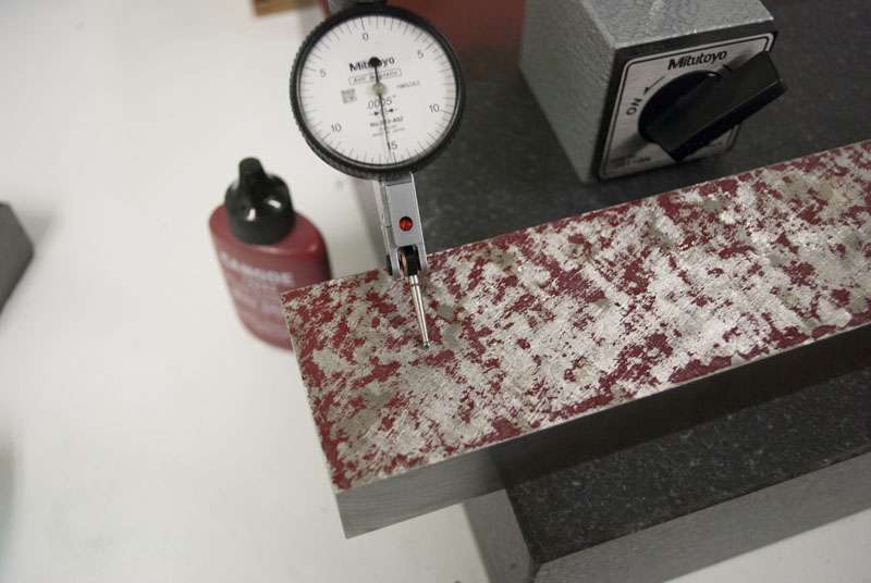
Spots alright, but the dremel does leave some pretty deep scratches. Not really something you are supposed to do, but the results seem okay.
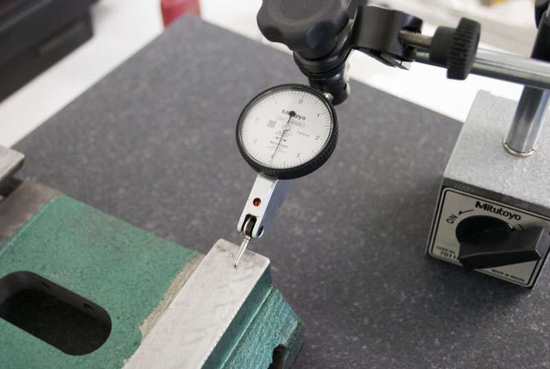
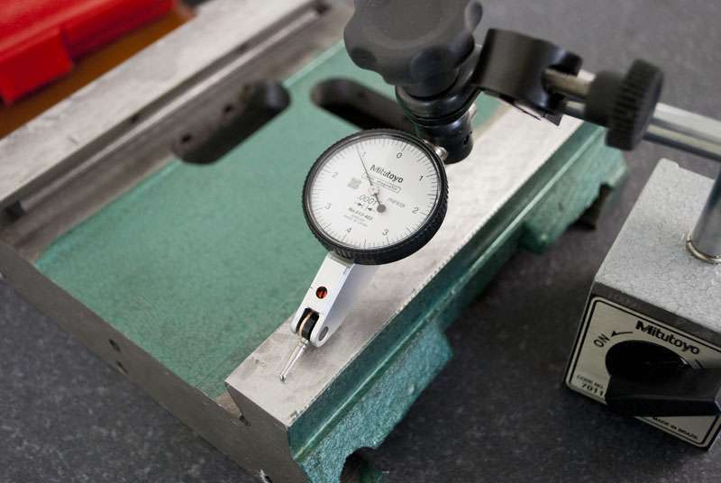
I checked the dremeled surface with an indicator, the bumps are about 0.3 thou above the low spots.
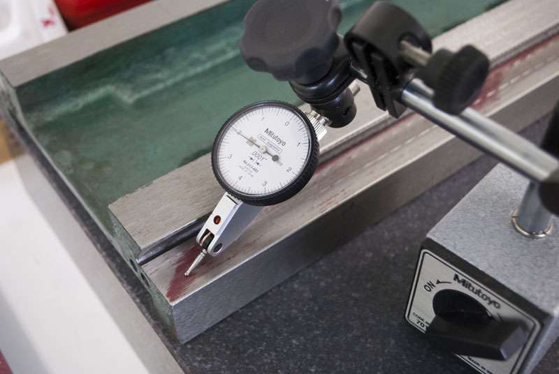
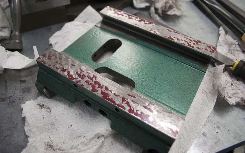
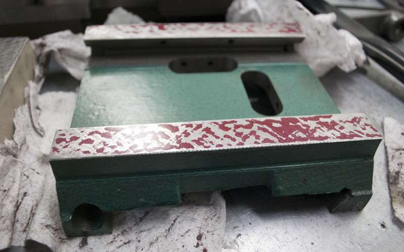
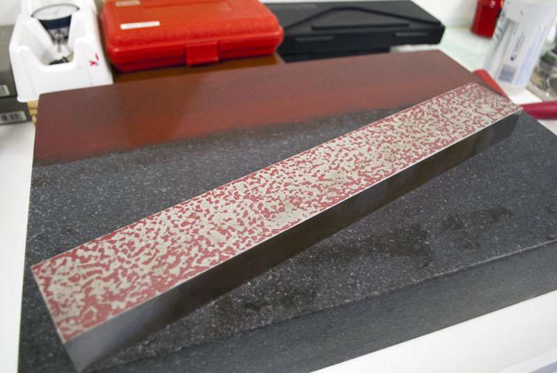
And properly scraped, I had to remove a fair deal more material to get it to spot nicely without scratches.
I left the straightedge fairly flat but not entirely finished, I spent two and a half days scraping the thing and I won't actually have that many uses for it.
Thread: Ryan's g0704...
Results 1 to 20 of 284
Hybrid View
-
07-01-2012, 06:02 AM #1
 Registered
- Join Date
- Apr 2005
- Posts
- 419
Ryan's g0704...
-
07-01-2012, 05:57 PM #2
Gold Member

- Join Date
- Nov 2009
- Posts
- 4415
Keep the pics and info coming. I want to see the process of scraping, specifically on the G0704.
-
07-02-2012, 02:39 AM #3
Gold Member
- Join Date
- May 2005
- Posts
- 3920
You are off to a nice start!
The G0704 is a nice place to start, further I see you are committed to doing it right by starting not on the mill but in the tooling.
That straight edge may come into use more often than you think. Once you have one you will find uses for it. Being a fresh piece of iron it will like stress relieve itself over time so you should check it before use each time until you are confident it is stable. This is one thing that is often forgotten, metal will move, let's hope though that your piece of iron is stable.
As a point of curiosity how much did that hunk of iron cost you?
The only thing that bothers me is the "stand that integrates column support". Frankly if you are going to all that trouble why not just build a full custom mill? Maybe my perspective is wrong but in order to provide realistic support you need to build a stiff frame. At that point why not go whole hog and do the horizontal and vertical columns? Another alternative would be to buy a bigger mill.
The thing is this, if the column is flexing excessively would it not be reasonable to assume the machine is being driven to hard? It isn't like these things come with hefty motors and reliable drive trains.
Well that is just me, I like where you are going otherwise.
-
07-02-2012, 04:07 AM #4
Registered
- Join Date
- Aug 2010
- Posts
- 278
Based on your first post i am guessing you will be running linuxCNC, since you have servos and encoders you get a closed loop system, with the linear glass encoders you know always the true position... How will that work together in linuxCNC?
Hive 8 - G0704 CNC Mill - 20 inch Telescope - High Resolution 3D Printer - Lasersaur 100W CO2 Cutter / Engraver
-
07-02-2012, 05:35 AM #5
Registered
- Join Date
- Apr 2005
- Posts
- 419
This is certainly a concern, I'll keep an eye on it. The iron cost about 40$ but shipping was pretty hefty. Getting it locally would have been a pain. Originally Posted by wizard

You certainly have a point, by the time this is done I expect to have paid 1200$ for a set of g0704 castings and a bag of trash. A scratch build is a fairly large jump in difficulty though. Keeping linear rail properly aligned looks very difficult. Originally Posted by wizard
I'm not comfortable building from scratch yet, but perhaps I'll get a power scraper and give it a shot for my next machine.
You are correct, and I wouldn't be reinforcing the column normally. I am concerned that the travel extension and 5th axis mod (which essentially adds 6" of spacers between the base, column and head) will give the cutting tool too much leverage on the column and reduce the mills rigidity. Originally Posted by wizard
KFlop claims to do this out of the box ( Dynomotion | Motion Control Boards ). Tuning both loops might get weird though since the inner loop is running on the DMM drivers but the outer loop is on the Kflop. Might as well see what happens. Originally Posted by hive8
Time for pictures...
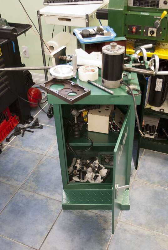
First step once the mill arrived was to strip it to castings, everything else ended up in the stand.
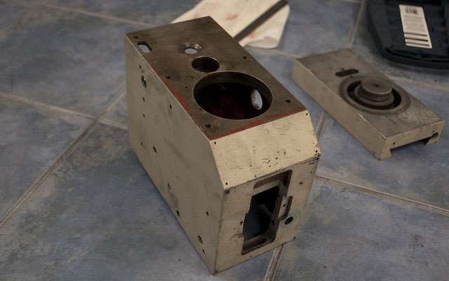
The head completely stripped.
Next step was to do a thorough analysis of all the castings. I started spotting the castings using my straight-edge. You can see the regular bumps left by grinding on the dovetail, the bottom surface looks okay.
The saddle is a real mess. Someone attemped scraping, but they probably just randomly hacked at the surfaces. The saddle is pretty far out and the gibs are horrendous. The front surface of the x axis gib has three nail sharp points of contact and the back is curved.
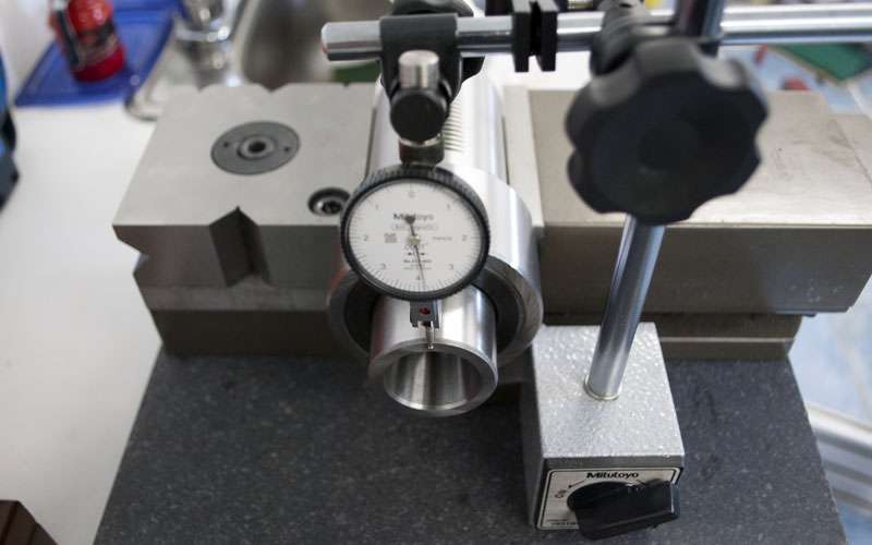
Zero an indicator on one corner...
And compare the height of another corner...
The saddle apprears to be wedge shaped by around 0.003", which is very odd.

The table is also a wedge. I really have no idea what is going on here, perhaps the two wedges offset each other or something funky. I plan on taking a much closer look to figure out what is going on before I try correcting it.
The Z axis looks alright. Same story as the other axes, ground surfaces look good, the hand scraped surfaces are bad and the gib is worse.
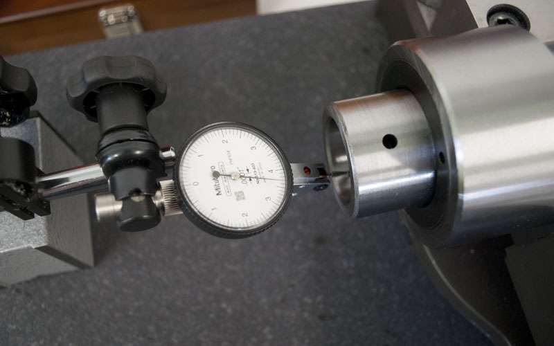
I took a look at the spindle as well. There seems to be +-0.0003" of runout in the taper which is pretty bad. Hopefully most of that is the bearings.
The face of the spindle looks fine. This only matters for TTS since you suck the tool against the spindle. If the front is at an angle the tooling will stick out at an angle.
I threw the mill back together to get a feel for its current performance. No point doing a bunch of work if I can't compare to the original numbers.
Unfortunately with the gibs in their current state it was very difficult to keep the machine rigid without locking the axes. It was possible to push the table around about 0.003" by hand which made measuring any alignment errors futile. To be fair, I don't have the screws in so you could probably go tighter normally.
I took a go at axis parallelism though since the axes had less wiggle in that direction, at first glance it appears that the X and Y axes are out of square by about 0.001" per foot.
I will probably try fixing the gibs and then I will take another set of measurements.
-
07-02-2012, 01:43 PM #6
Gold Member
- Join Date
- Jan 2010
- Posts
- 2141
Just curious - what method did you use to strip the head casting?
How long did it take?
-
07-02-2012, 04:38 PM #7
Registered
- Join Date
- May 2011
- Posts
- 308
+/- .0003" is very close to what I measured as well. Mine may have been closer to +/- .0002". I didn't see any difference in the reading when I swapped the bearings. For me it helps if I say '$950 mill' two or three times in the morning before I start working. On the other hand I don't expect you will see much better spindle run out on the average Bridgeport clone out there.
It would be great if we could share some ideas in this thread regarding the stiffening of the collum on the G0704. I think a little effort in this area could go a long way.
-
07-02-2012, 05:35 PM #8
Registered
- Join Date
- May 2007
- Posts
- 89
those specs are actually pretty darn good considering as you mentioned the whole mill is only a grand. too many of the inexperienced here don't have a clue what things cost in a real shop and have insane expectations of these imports. this runout is good for the quality of the bearings used, this mill doesn't have $500 in bearings so don't expect the tolerances of ones that do. Originally Posted by Turbo442
use some common sense.
-
07-02-2012, 08:01 PM #9
Registered
- Join Date
- May 2007
- Posts
- 89
excuse me whizbang but i don't think anyone said anything negative about ryans adventure in scraping but actually commented about the spindle runout. it has been pointed out though that what you get for your money isn't that terrible considering you bought the very lowest priced version of these machines. from reading here there seem to be much more expensive models that aren't so popular that you could have purchased instead where there is likely more attention paid to tolerances and uniformity. these bargain mills are cranked out asap to supply demand so inconsistencies from one machine to the next are to be expected. your situation seems to bear this out. ryans may be off .003 but yours could be .001 or .005 at the same measuring point. you can try to scrape it but following someone that is learning as they go might just turn out to be a story of what not to do, no offense.
-
07-02-2012, 08:33 PM #10
Erfahrener Benutzer
- Join Date
- Feb 2012
- Posts
- 234
I stand corrected. The way I read comments I interpreted them as negative (sorry) Also the class is the 21st(typo) there is a listing on ebay if anyone is intrested with 2 seats left.
Lastly as someone who has never scraped before, what would the ball park cost of having a machine this size scraped in cost? Ryan seems to have access to another mill that he can make tools to assist in the scraping process. Some of us may not and a iron straght edge on ebay seems pretty expensive and thats just one of the tools plus, the amount of time put into the actual process.
24 1/2" Cast Iron Camel Back Dovetail Straight Edge | eBay
thats just one tool needed. Would my cost of all tools needed exceed the cost to have it done commercially?
-
07-02-2012, 10:14 PM #11
Gold Member
- Join Date
- May 2005
- Posts
- 3920
No problem, it looks like the guy is off to a good start! Originally Posted by Whizbang
It has been a very long time since one was done at work, so I don't have a price for you. A business though would likely be charging well over $60 an hour. Hopefully someone that has had work done on a machine recently can comment. Just from following this thread you can see that lots of time is involved. A professional tool rebuilder might put machine parts like this on a way grinder to start.Lastly as someone who has never scraped before, what would the ball park cost of having a machine this size scraped in cost?
This is a huge problem in a home shop. Your only option is to have somebody else fabricate the straight edge or find a suitable one in the marketplace. As for the surface plated it may be desirable to get one for your shop. They are very useful to have around.Ryan seems to have access to another mill that he can make tools to assist in the scraping process. Some of us may not and a iron straght edge on ebay seems pretty expensive and thats just one of the tools plus, the amount of time put into the actual process.
Probably not. Straight edges seem to be as rare as hens teeth and the people owning them seem to value them highly as you can see by that price. I'm not sure why this is the case, the casting is fairly simple. One person I know of recommended searching junk yards for scrapped machine where you might be able to cut the ways outand reuse them as straight edges. To me that seems a little extreme when one can simply machine one out of cast iron bar suitable for our machines.24 1/2" Cast Iron Camel Back Dovetail Straight Edge | eBay
thats just one tool needed. Would my cost of all tools needed exceed the cost to have it done commercially?
-
07-02-2012, 10:35 PM #12
Erfahrener Benutzer
- Join Date
- Feb 2012
- Posts
- 234
I do have a friend with a old surface grinder. His mill is way out he only uses it for wood and says he wouldnt trust it. As far as power scrapers go. i just grabbed a good old harbor freight multifunction oscilating tool and bent a piece of steel to fit and tried scraping with it, it didnt look the prettiest but it did remove a high spot on a piece of steel i had sitting around. maybe this tool can be adapted to aid in the scraping process. can't wait to see more on this thread
-
07-02-2012, 08:35 PM #13
Registered
- Join Date
- Aug 2010
- Posts
- 278
I saw you are using a granite 90 degree plate (not sure if i call this the right name) where did you get that from, i am looking for something like that as well...
Hive 8 - G0704 CNC Mill - 20 inch Telescope - High Resolution 3D Printer - Lasersaur 100W CO2 Cutter / Engraver
-
07-02-2012, 08:47 PM #14
Erfahrener Benutzer
- Join Date
- Feb 2012
- Posts
- 234
smallest and cheapest square at shars
shars.com - 10quot x 6quot x 1quot Precision Granite Square
-
07-02-2012, 10:05 PM #15
Registered
- Join Date
- Apr 2005
- Posts
- 419
Just a hammer (+hex keys and screwdrivers) and the exploded drawing in the manual. I knew that I wanted to leave nothing behind so I ripped off everything that wasn't part of the iron. Probably took about an hour, there were a few quirks but when I got stuck I was able to google the part I wanted to remove and there was usually already a thread on cnczone about it. Originally Posted by doorknob
I suppose you are right. At this point I am more interested in ways it can be corrected. Assuming that the runout is in the spindle and not the bearings, perhaps I can mark the high spot and take a couple swipes with 1000 grit+ sandpaper (in the locations where the spindle contacts the bearings, not in the taper). Originally Posted by johnedward
I'm also considering turning my own TTS holders, and I could bore then out on the mill (holding the cutting tool in a vice on the table). As long as I always use the holders in the same orientation that should have zero runout.
Just ideas, it will be a long time before I have a spindle that turns.
A worthwhile disclaimer, probably worth watching for a while before committing to a process that may or may not work out. Originally Posted by johnedward
Whizbang linked the correct square from shars. Kinda expensive but if you want to check machine alignments you need a square. Make sure you check the tolerances on whatever square you buy. Originally Posted by hive8
Paying someone to do it is probably out of the question, as was mentioned it would cost significantly more than the mill itself. Originally Posted by Whizbang
Tool cost depends a lot on how much you want to correct and what tools you already have. Things like a surface plate, indicators and square are useful in general. A straightedge and scraper can be improvised, and you should probably scrape your own straightedge for practice.
If you are scraping purely for fit (rigidity and smoothness of motion) and don't care about alignments (which should be within a thou or two anyways) you could get away with a scraper and a tube of spotting ink. The processes and what equipment they require will become more clear once I get further along.
___
As always, it's worth pointing out that I don't need this machine for production or anything, and I am aware that what I am doing is not necessarilly an efficient use of time or money. I'm having fun and I'm curious to see what kind of return a novice can get from scraping.
-
07-03-2012, 12:09 AM #16
Gold Member
- Join Date
- Jan 2010
- Posts
- 2141
Actually, I was thinking about the paint, sorry if my question was unclear... Originally Posted by 691175002
-
07-03-2012, 05:31 AM #17
Registered
- Join Date
- Aug 2010
- Posts
- 278
May i ask where you bought your hand scraping tool?
Hive 8 - G0704 CNC Mill - 20 inch Telescope - High Resolution 3D Printer - Lasersaur 100W CO2 Cutter / Engraver
-
07-03-2012, 07:14 AM #18
Registered
- Join Date
- Apr 2005
- Posts
- 419
Sorry, I was unclear as well. The paint is still on the casting. I intend to sand and repaint later though. I really have no clue how one goes about repainting a mill but I've heard stripping all the way adds a lot of work because there is a tonne of bondo on the castings. Originally Posted by doorknob
I bought a carbide scraper from Hand Scraping Tools . I did enough scraping that I consider the carbide worthwhile, but you have to make sure you have the equipment to sharpen it. Originally Posted by hive8
One mistake I made was getting only a single blade. Get at least one spare because you need different edges for different stages of scraping.
___
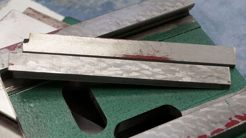
As I mentioned earlier, I wanted to do something minor to the gibs and then see if I could get a more reliable error measurement.
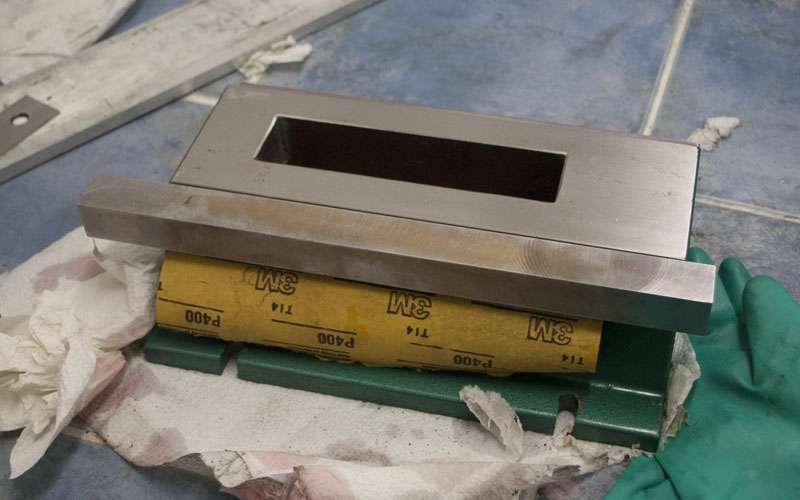
The most basic way to fix the gibs is sanding them against something flat. Almost anything will do, I used a piece of glass and a sheet of 400 grit wet/dry sandpaper.
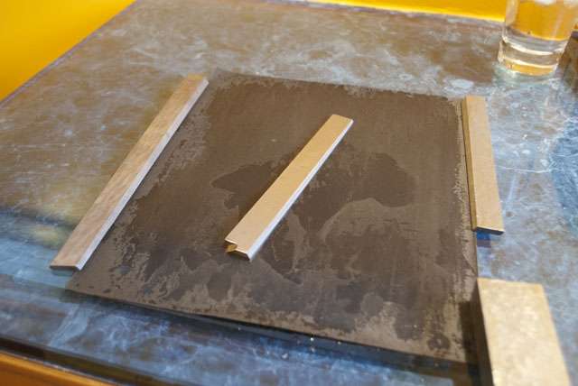
This was a very simple job and if you compare the contact now to the original gib the difference is incredible. I didn't spend as much time as I could have, but make sure you leave a few bumps to hold oil.
I also figured I might as well give the straightedge a go as well. The g0704 comes with milling marks left in the ways (for oil retention) but they are still fairly sharp out of the box. I just took a few swipes with 400 grit for fun.
_____
Before I focus on correcting the alignment errors in my g0704 it is a good idea to understand what errors can be present in a mill.
Accuracy is often quoted (or even measured) as a single number, but that is very simplistic. Almost all accuracy tests only measure a very small subset of the total possible errors.
Here is an official "Parametric Errors of a Three Axis Machine" chart, there are 7 errors per axis for a total of 21:
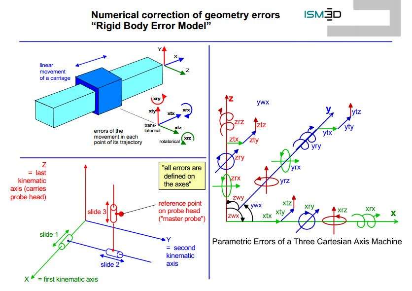
It isn't actually as complicated as the picture looks (Each axis has x,y,z, roll, pitch, yaw and linear error) but I've made a quick diagram for the most common errors.
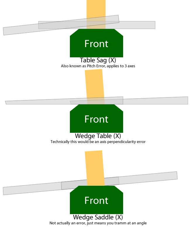
Table sag tends to be the largest error because of the design of most hobby mills. When you move the table all the way to one end, it has tremendous leverage on the saddle and if there is any looseness in the gibs the center of the table will lift. You also start cutting at an angle; this is a pretty nasty error and very hard to eliminate.
I've coined the term wedge table because it exists on my mill. This is actually axis perpendicularity (or Z error in the X axis).
A wedge saddle also exists on my mill. It does not actually cause any error because you can tramm the column to match.
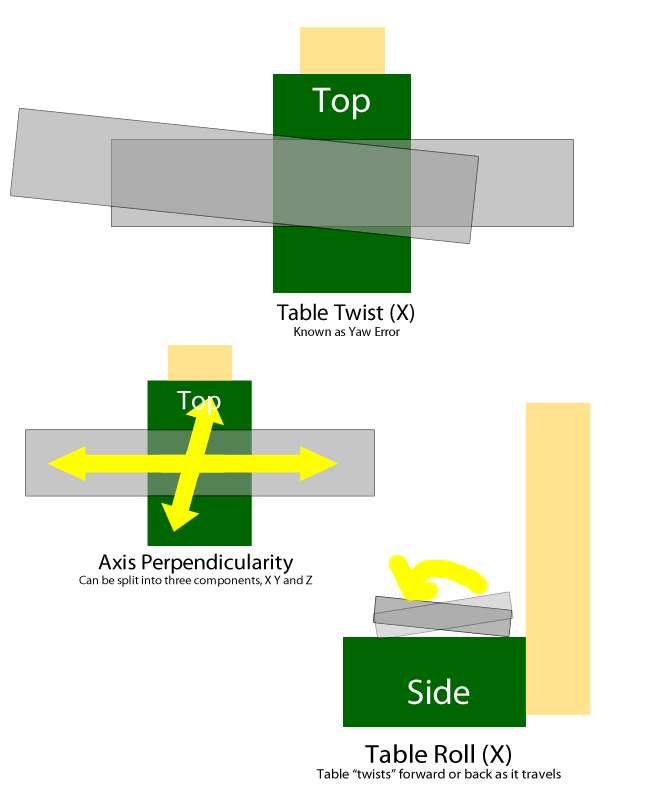
Table twist is fairly straightforward.
Axis perpendicularity is also fairly straightforward. Some axis perpendicularity errors are easily fixed (column tram) whereas others are a result of machine geometry (x/y perpendicularity).
Table roll is kinda like table twist just in a different axis.
Note that if all the sliding surfaces of a machine are perfectly flat, parallel and perpendicular where they should be the machine will have no errors. If you can verify that the alignments in the machine are correct there is no need to measure the resulting errors (or lack of errors).
____
Because the ground surfaces (aka the dovetail ways) all appear to be relatively true, I will assume they are perfect until proven otherwise. Scraping the ways will be a tremendous amount of work and I would probably need both a larger surface plate and a larger straight-edge.
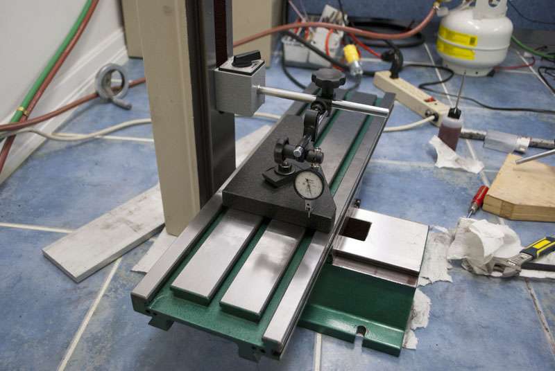
To start, I will focus primarily on measuring table sag by putting an indicator on the table and sliding the table back and forth.
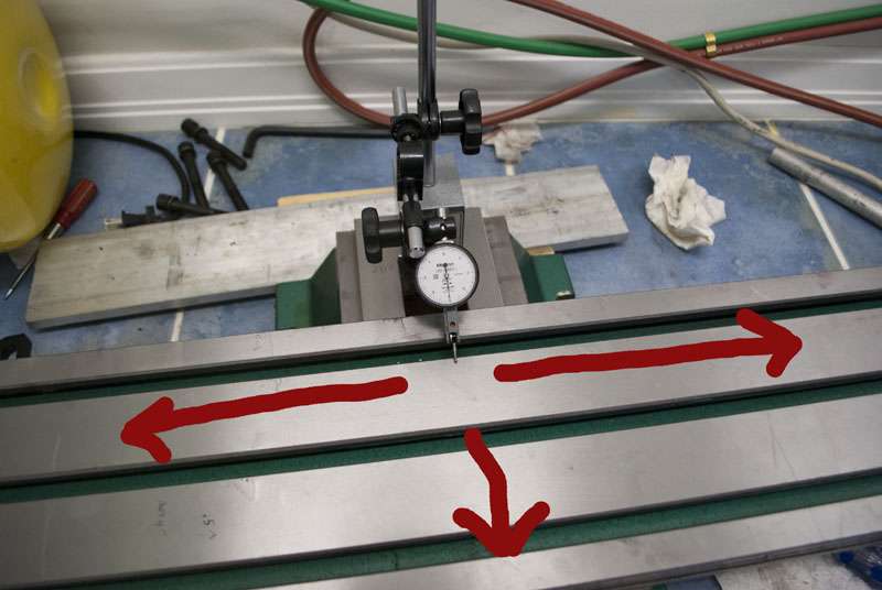
Table sag is basically an easy way to measure any looseness/poor fits in the mill. Here is a comparison of the errors before and after lapping the gibs:
- Flex: 0.003" -> 0.001"
- Table Sag (2" from ends): 0.002"->0.0015"
- Sag (At end of travel): 0.004"->0.002"
It was fairly easy to feel the difference when adjusting the gibs as well. Before it was either loose or locked whereas now there is more of a sweet spot.
Right now the flex still left in the machine still masks any other errors so I will start scraping.
____
The idea behind scraping is to cover a reference surface with a very thin layer of ink. You then rub the workpiece against the ink and it will transfer only to the points that touch. You want as much contact as possible between the two surfaces so you scrape off the high spots (where the ink has transfered) and repeat.
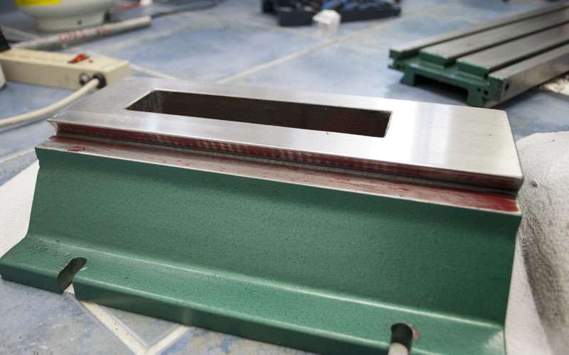
The first surface I will be scraping is the bottom of the saddle. I have chosen to start by scraping to a surface plate since that is easiest to spot off.
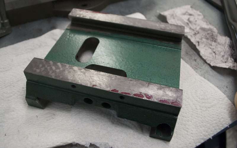
This is the saddle in its original state. Consider that all the forces the mill is under are being transfered only by the inked points. The rest of the iron is pretty much just hanging around.
A bit of scraping, there still isn't that much contact but now the entire surface has high spots instead of just two corners.
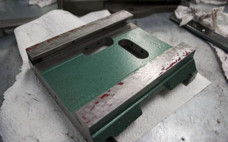
Getting closer. The process slows down a lot as you get further along because there is so much more material to remove per step.
And done for now. This surface has not yet been finished but I am putting that off for later.
-
07-03-2012, 12:56 PM #19
Registered
- Join Date
- Feb 2012
- Posts
- 296
Wow thanks a ton for all the pictures, diagrams, and detailed info!
You are going to greatly help a lot of people, like myself, who are very new to these machines.
What kind of tolerance are you aiming for once you are all done with everything? Do you want to be able to hold a thou or two? I am hoping you don't have to do all that work to hold five thou.
-
07-03-2012, 05:59 PM #20
Registered
- Join Date
- Apr 2005
- Posts
- 419
I'll use numbers that ignore the last few inches of X travel, since the ends of the table are rarely used and doing so more than doubles the total error. Originally Posted by DRock
I think a stock g0704 can hold to 0.002" per foot for each axis as long as the gibs aren't completely messed up (and the column is properly trammed).
You can then add in your backlash/leadscrew error which will be about 0.002" (backlash+slop after compensation) + 0.002"/Foot (leadscrew pitch error) depending on how you set up the machine.
These are pretty much just guesses, but the total error would be 0.002" + 0.004"/foot (per axis) which seems reasonable.
I think an ambitious goal would be a geometry error of 0.0005"/Foot. With glass scales I should have zero leadscrew pitch error and backlash/slop should be around 0.0004".
This comes to 0.0004" + 0.0005"/foot per axis.
Of course, in this range you need to start worrying about thermal expansion and machine rigidity so I don't expect to hold that in a cut.
I'm also just guessing numbers. I don't actually know how this will turn out.

 Reply With Quote
Similar Threads
-
G0704
By kd4gij in forum Benchtop MachinesReplies: 8Last Post: 07-07-2016, 12:00 AM -
DRO for G0704
By UMR in forum Benchtop MachinesReplies: 4Last Post: 07-06-2016, 04:04 AM -
No Joy with my New G0704
By DogWood in forum Benchtop MachinesReplies: 5Last Post: 07-05-2016, 05:49 PM -
G0704... Yes Another One ;)
By ww_kayak in forum Benchtop MachinesReplies: 24Last Post: 05-27-2013, 03:47 PM -
G0704 or a X-3
By USN in forum Benchtop MachinesReplies: 8Last Post: 05-30-2011, 08:24 AM
