


So it seems that the best "bang for your buck" is to lap the machine and call it a day.
I am not looking to hold any crazy tolerances myself, such as .0005", but it would be nice to hold +/- .002" without having to scrape the machine.
Is lapping as simple as putting some compound on the ways and then sliding it until it feels smooth? Will it help the Table Z error?
Thanks again.
Thread: Ryan's g0704...
Results 41 to 60 of 284
-
07-16-2012, 10:17 PM #41
 Registered
- Join Date
- Feb 2012
- Posts
- 296
-
07-16-2012, 11:29 PM #42
Registered
- Join Date
- Apr 2005
- Posts
- 419
Lapping is pretty much as you described. There are really just some common sense things to keep in mind: Originally Posted by DRock

- Take the mill apart, lay the table/base/column out flat and push the saddle/z slide by hand so you can feel how things are going and so that gravity does not mess with alignments.
- Make sure that you perform complete "strokes" from one end of the travel to the other because if you miss spots (or repeat spots) they will wear unevenly.
- Tighten the gibs as you lap, since the way will loosen up as you remove material.
- Try to keep the force in the direction of travel, if you apply a lot of twist or do something weird it might change the alignments.
- If in doubt, stop early. Lapped areas will become shiny and once 30-50% of the surface is making contact you should probably stop.
Nothing is particularly important since very little material is removed, but you might as well do the best job possible.
Lapping will improve the table Z error by a significant amount. I mixed oil with my lapping compound to make things easier to push but I've heard of people using compound straight or mixed with kerosene as well.
-
07-18-2012, 04:42 PM #43
Registered
- Join Date
- Apr 2005
- Posts
- 419
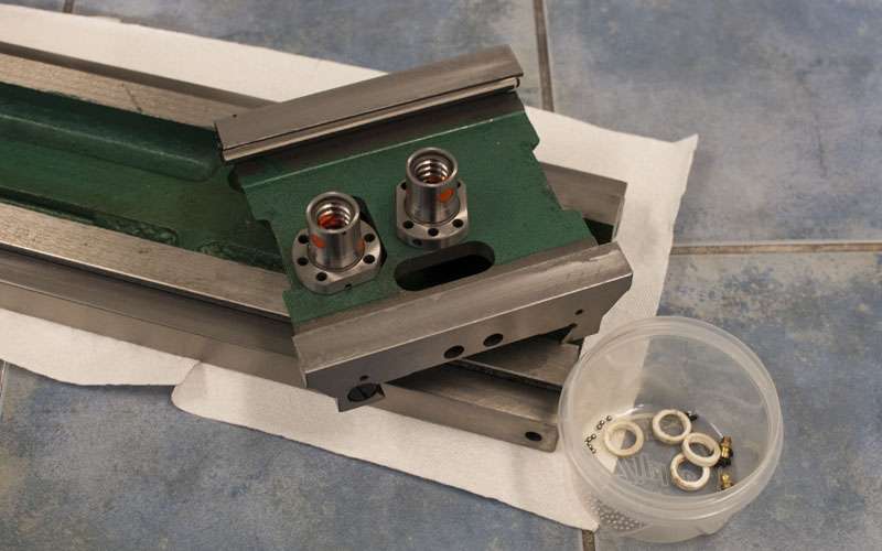
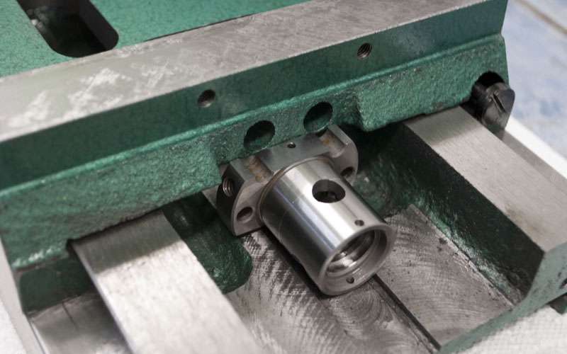
Unfortunately, fitting 6 ball nuts into a g0704 looks like it is going to take some effort. I want to keep full X travel and increase the Y and Z travel in the process but at the same time I want to avoid removing too much iron from the castings.
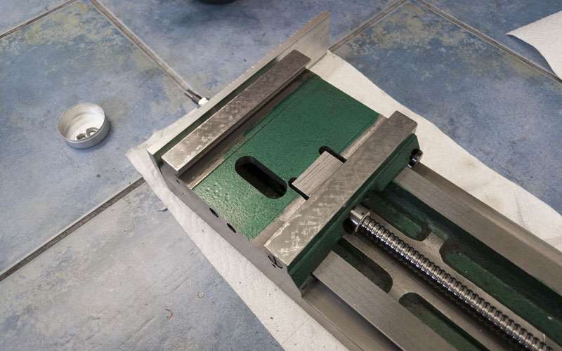
Ballnuts and saddle:
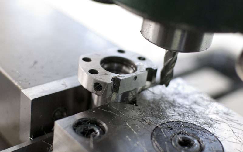
Machining the flange down:
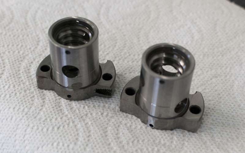
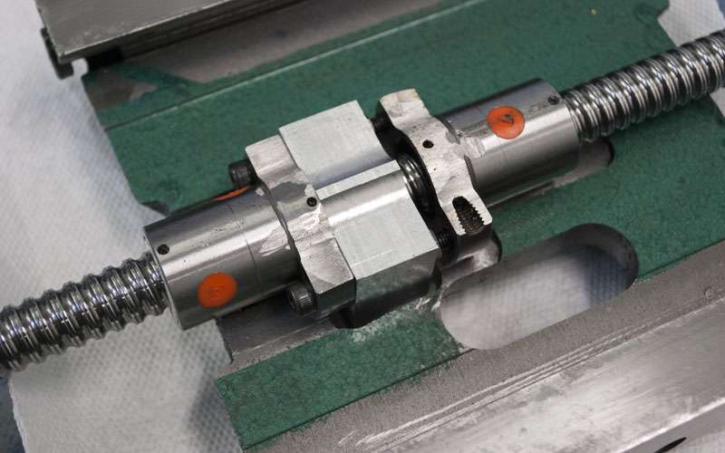
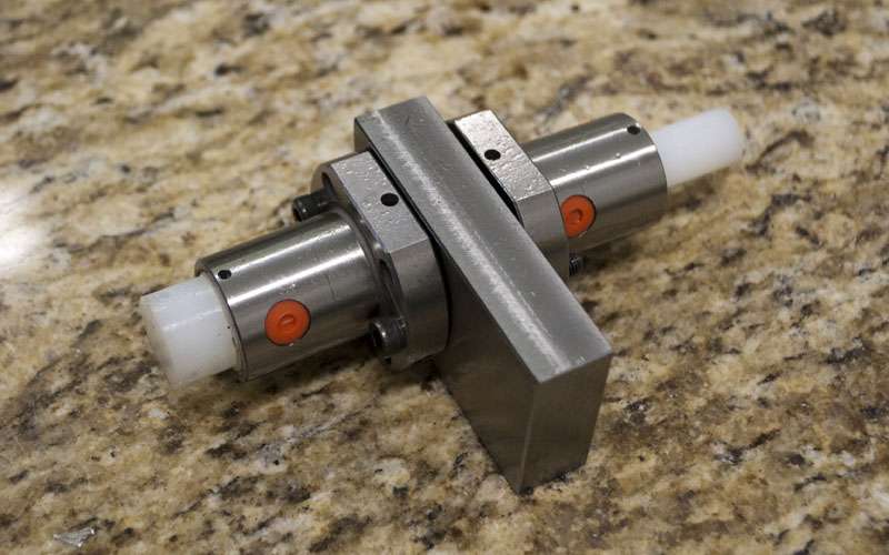
Machined ballnuts:

I realized that I would need to remove even more material so I ended up taking a grinder to them as well:
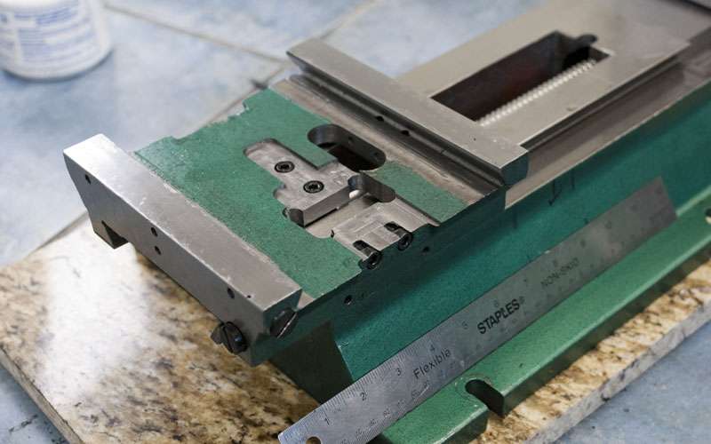
The saddle is a lot lighter than the table so I decided to take a few mm off the table instead of pocketing a giant rectangle in the saddle.
With the clearance in the table, now I only need a tiny bit more room for the saddle.
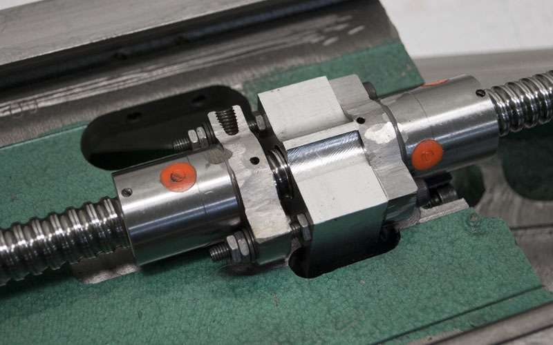
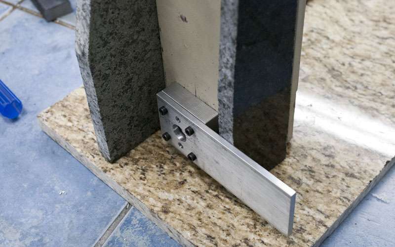
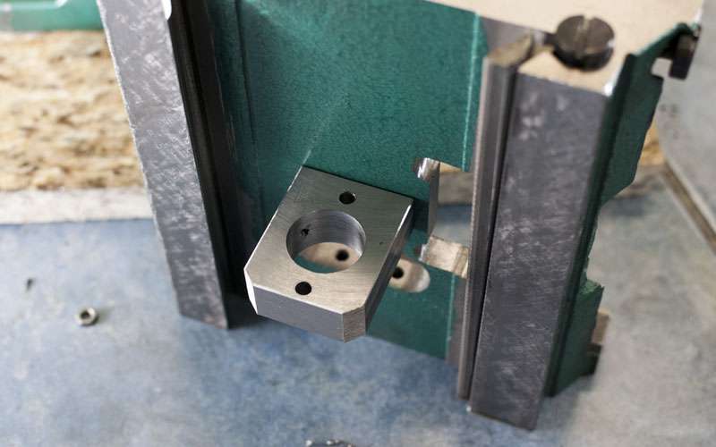
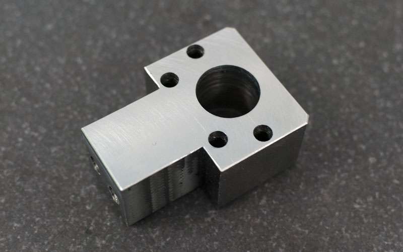
Ballnut mount:
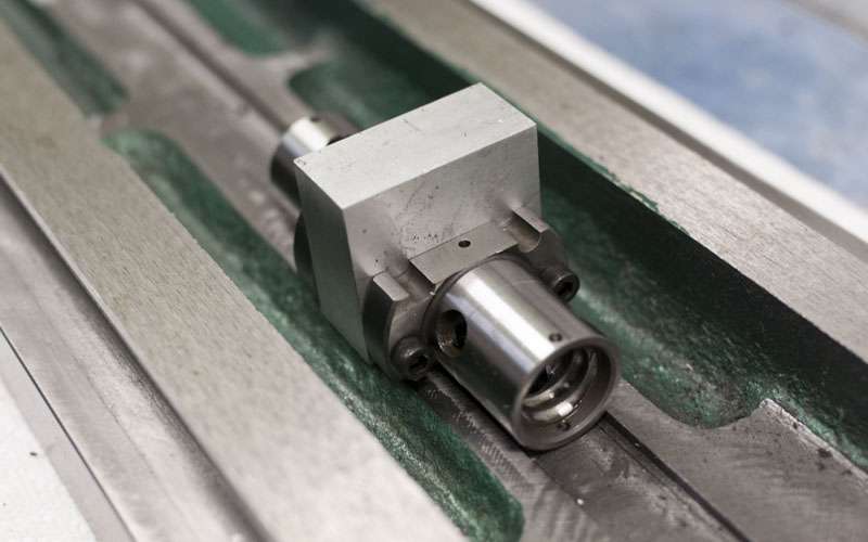
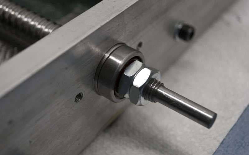
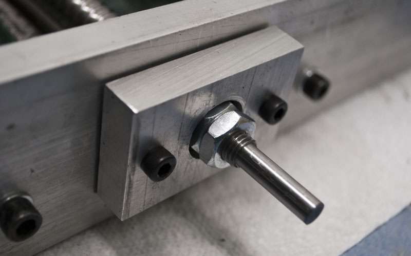
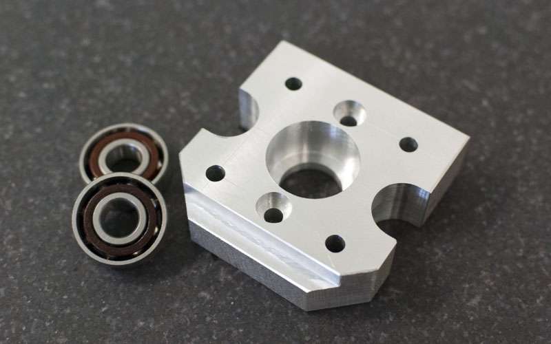
Starting work on the bearing/stepper mounts:
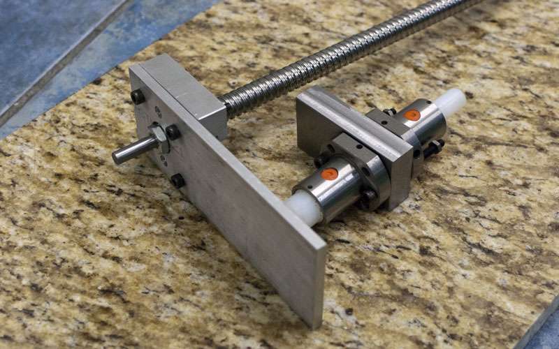
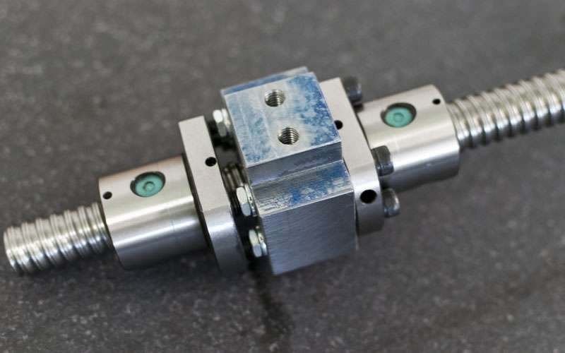
Repacking the ballnuts:
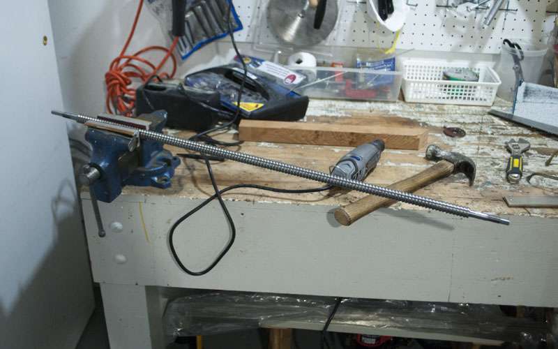
And testing:
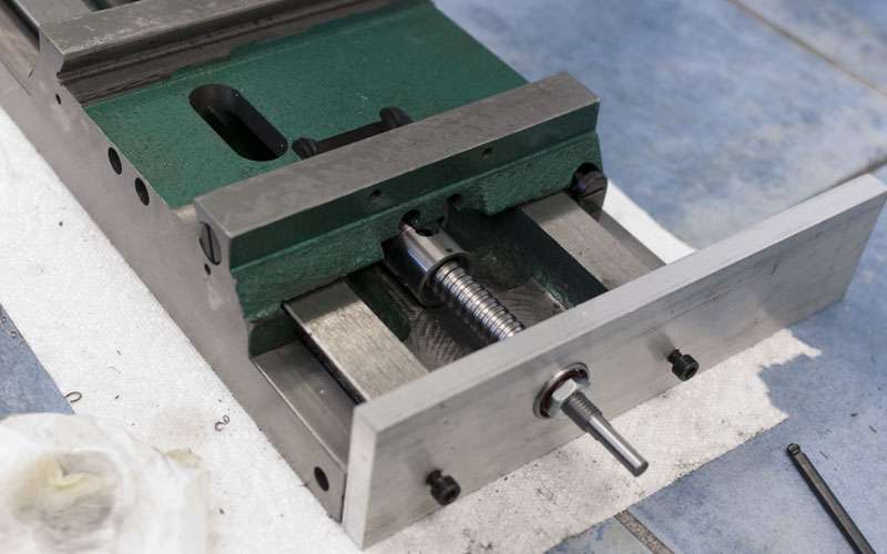
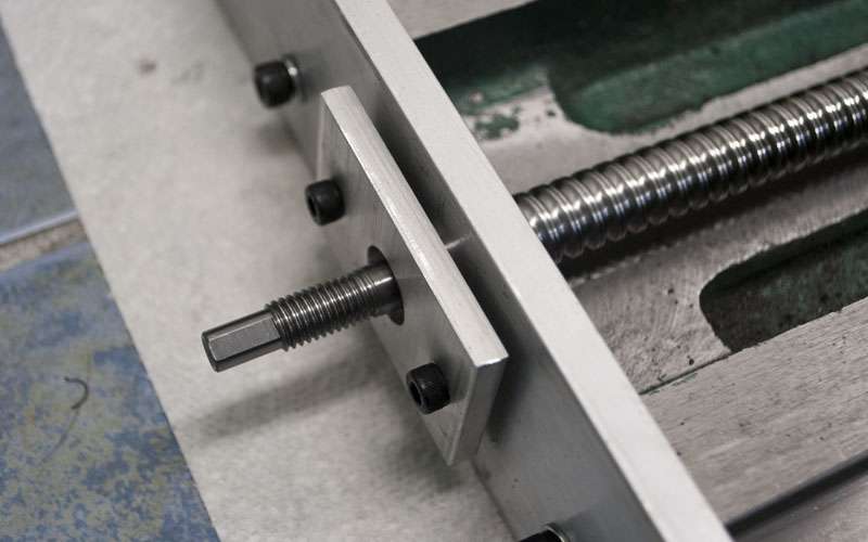
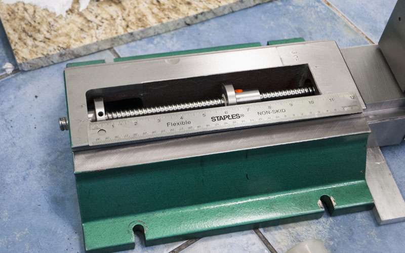
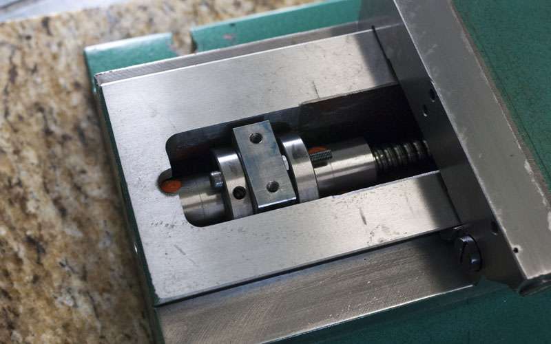
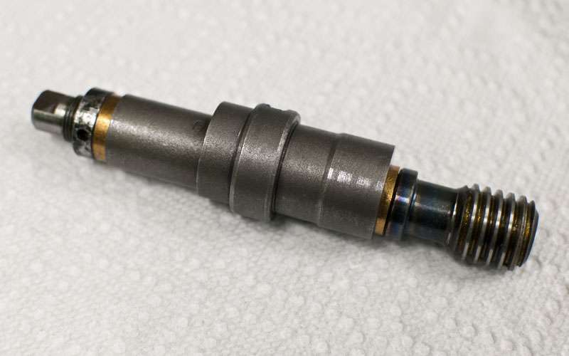
Turns out my ballscrew is bent. It took about an hour of switching between the surface plate and vice to straighten by hand but I got it pretty close. If you apply force by hand you can adjust the screw in very small increments.
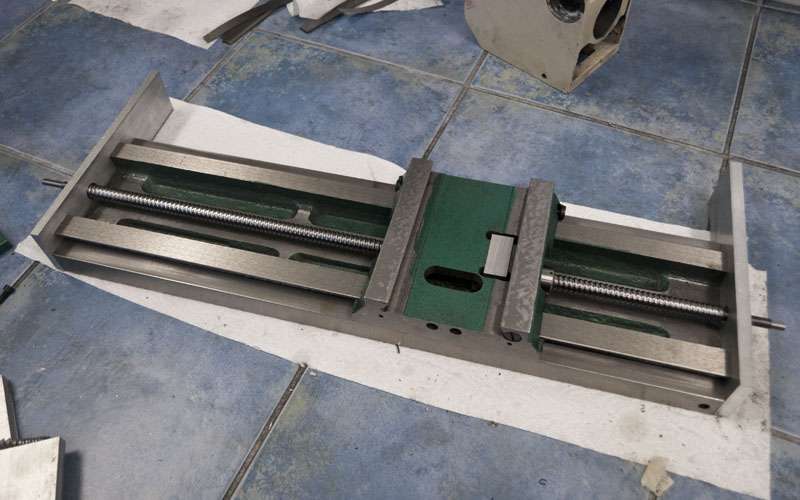
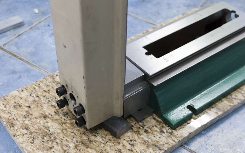
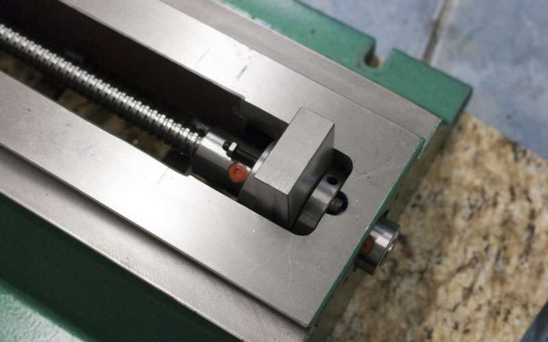
Another view of the saddle/ballnuts:
The straightened ballscrew can go to the extremes of travel very smoothly.
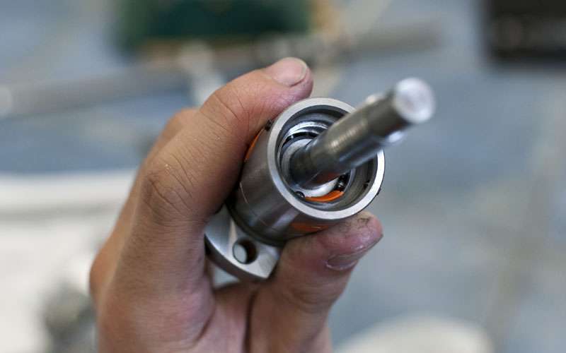
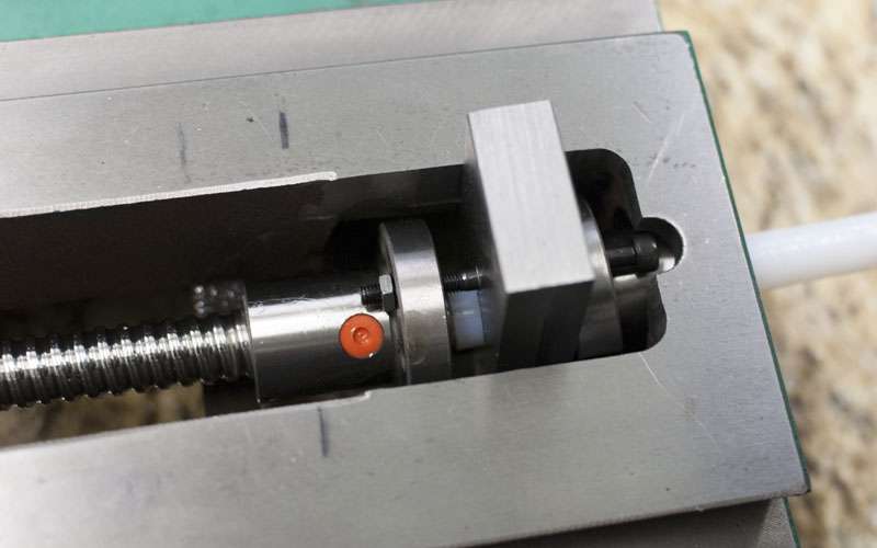
Preload applied, about 120lb. You can really feel the difference. The screw has a lot of "drag" and is harder to rotate by hand. It still feels smooth though.
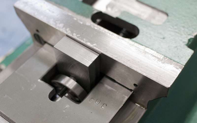
Preloading the bearings properly was a little more involved. I used a DF configuration and tried spacers in 0.001" increments until the bearings locked then backed off. I ended up going with a 0.004" shim here.
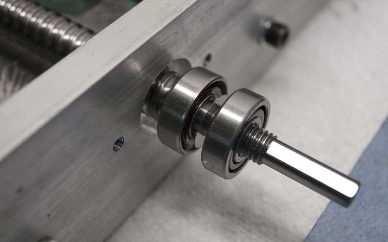
The floating end is a single deep groove bearing, no nut.
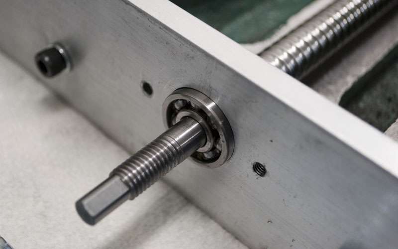
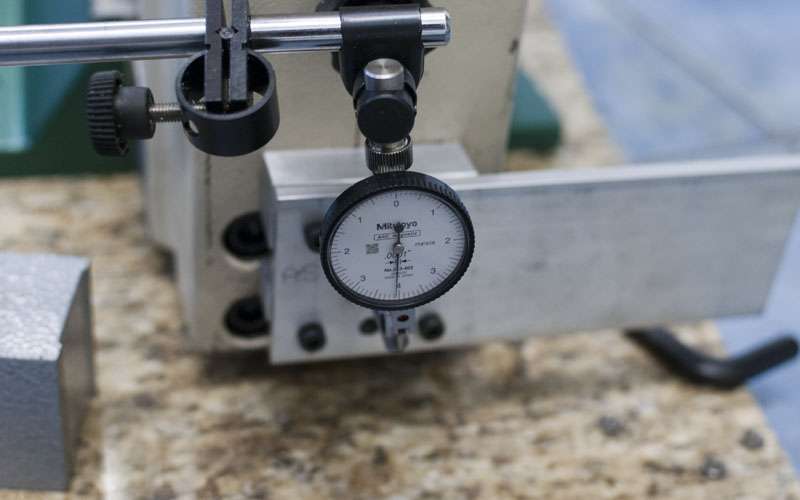
It is hard to evaluate performance since if I apply too much force the screw backdrives, but if I play with the screw by hand I cannot detect any backlash.
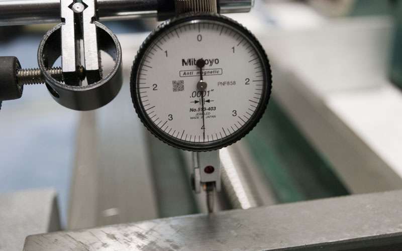
The bearings deflect about 0.0003" under what I would consider to be a fairly hefty load. I might be able to increase the spacer thickness by a few tenths but I suspect that bearings in this size range will always have measurable deflection.
I also picked up some bearings I hope to use for the 5th axis.
-
07-18-2012, 06:06 PM #44
Registered
- Join Date
- Aug 2008
- Posts
- 962
691175002,
Your build is quite interesting & informative .. I for one like the abundance of pictures .. keep them coming!
I also have what appears to be the same round column mill as you, but opted to keep mine manual. It has served me well for several years & although a bit of a pain when you can't avoid moving the head .. still a capable little machine. I still find myself using it a fair amount for quick little milling & drilling applications.
gd.marsh
-
07-19-2012, 03:58 AM #45
Registered
- Join Date
- Feb 2012
- Posts
- 296
Lookin good.
What are those gold nipples that come on the ballnuts? I just noticed those and I am thinking maybe I can use those when I do my one shot oiling system.
It looks like you machined them both off though so I am not sure if I can actually plan on having them there or not.
-
07-19-2012, 05:27 AM #46
Registered
- Join Date
- Apr 2005
- Posts
- 419
I disliked the round column at first but now that I am used to working around it, the mill is nice. It has certainly performed quite admirably on this project, some of the later cuts I take into the g0704 are pretty hefty.
I might convert it back to manual and use its steppers for an ATC or other accessories when the g0704 is cutting.
The brass barbs come with the ballnuts and are intended for oiling. They fit 1/4" tubing and have a built in check valve which is pretty cool.
I currently plan on providing oil to one ballnut on each axis (as well as all the dovetails). Fitting everything into the saddle is going to be brutal.
-
07-20-2012, 03:51 AM #47
Registered
- Join Date
- Apr 2005
- Posts
- 419
Now that the X axis is mostly finished, it is time for the Y axis.
I was hoping the X axis would be the most difficult because of how hard it was to squeeze in two ballnuts but extending the Y travel turned out to be just as messy.
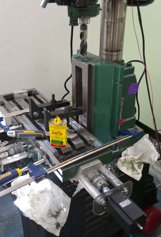
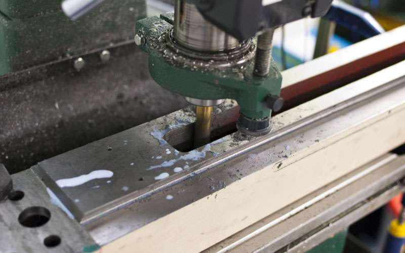
Started with the Y axis spacer. I choose to use steel instead of aluminium since my spacer will be 2.6" thick.
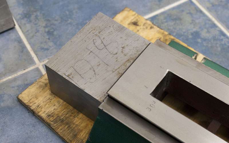
The block is a lot larger than I need. I'm pretty sure cutting it singlehandedly destroyed my bandsaw blade.
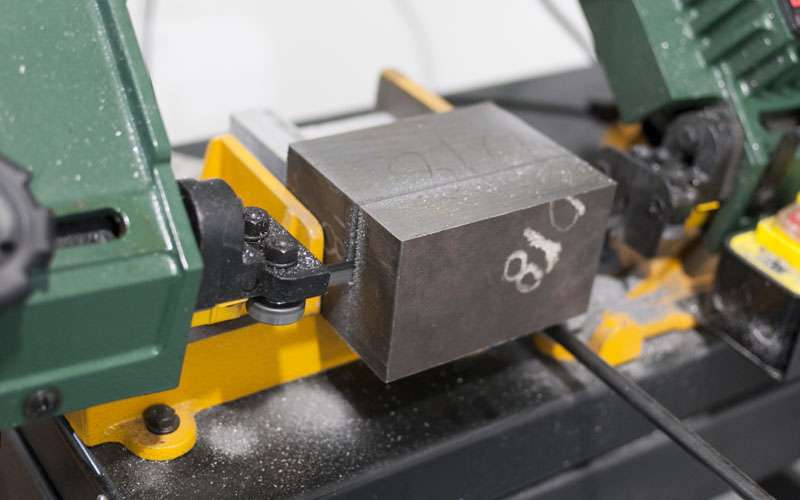
This is actually the first steel I have machined and I was a little too aggressive at the start. I had an endmill pull out of the collet and such but it still turned out okay.
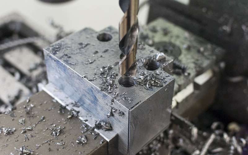
The finished spacer. Machining steel sucks, I don't even remember how many hours this thing took from start to finish.
Time for something completely different. When I was first brainstorming for the build I was thinking about ways to add rigidity/vibration damping to a mill.
I considered an epoxy granite fill, but that would be a lot of trouble and there isn't much room in the g0704 anyways. I also considered bolting the mill to a surface plate but that would be ridiculously heavy and would not help the column at all.
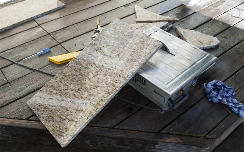
I ended up going through a scrap bin at a granite countertop place and pulled out these slabs for free.
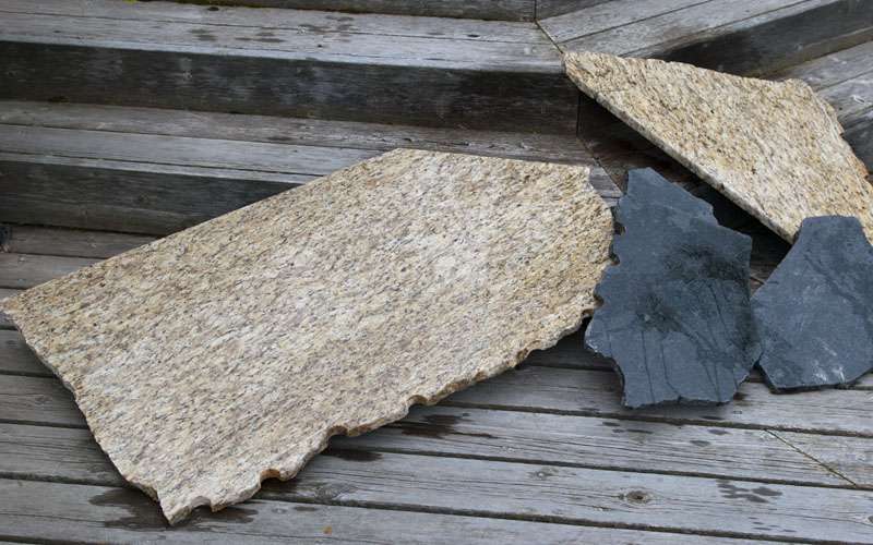
The stuff cuts surprisingly easy on a tile saw (with correct blade).
The final plan is to bolt together something like this. The weight should dampen vibration well and I'd imagine it will improve rigidity as well.
Onwards to the Y axis...
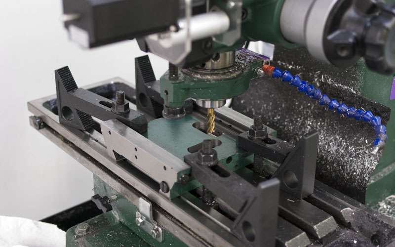
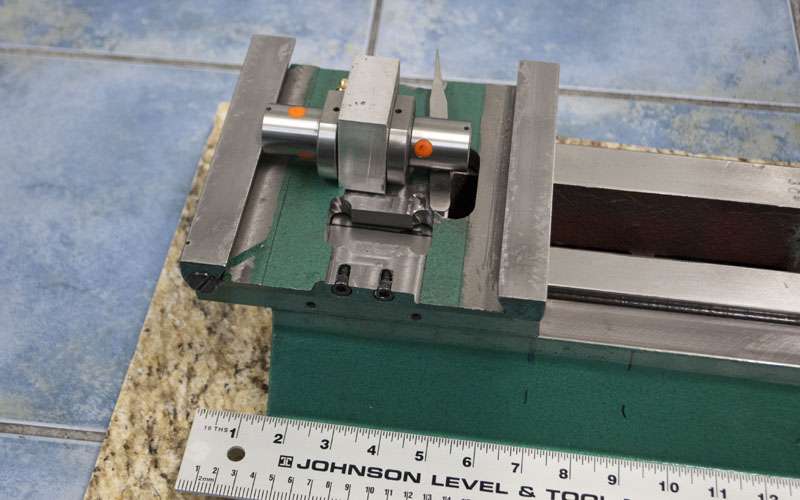
I want to squeeze as much travel out of my Y axis as possible but I do not want to remove too much material from the castings.
I hope to go around this far back, the extra room will be for bellows.
And this far forward.
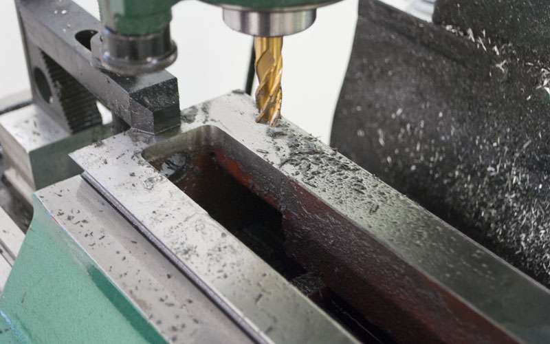
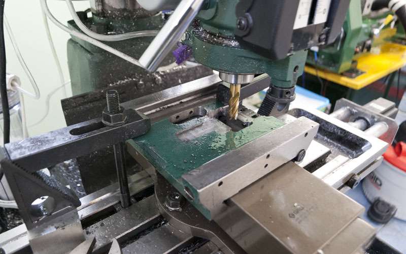
I didn't have enough z travel so I ended up doing something pretty wacky.
Cleaned out the holes with an endmill.
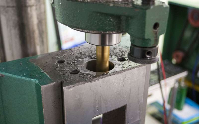
So now the ballnuts can go into the casting.
I used steel for the Y axis ballnut mount since it is a little thinner.
Ballscrew mount:
Same deal as the X axis, I test fitted shims until I was satisfied with the preload.

That's all for today.
-
07-23-2012, 05:05 PM #48
Registered
- Join Date
- Apr 2005
- Posts
- 419
Continuation of the y axis...
Reattaching the column to the base.
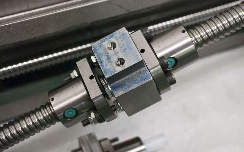
Transfering the ballnuts from the plastic rod to the ballscrew. One issue with using double preloaded nuts on every axis is that they are very hard to assemble in place.
I get some pretty nice travel through the front of the casting.
Sizing up the ballnut mount:
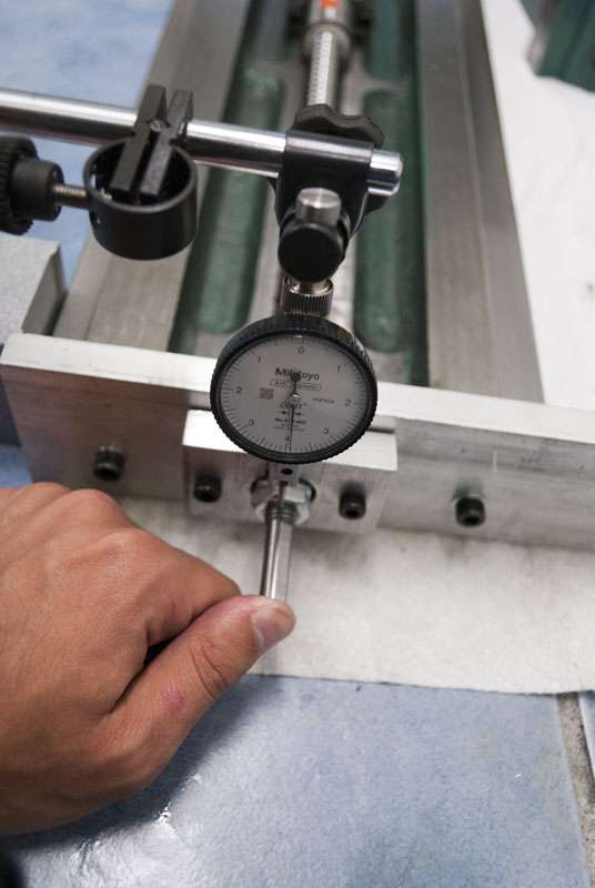
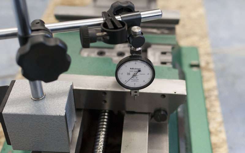
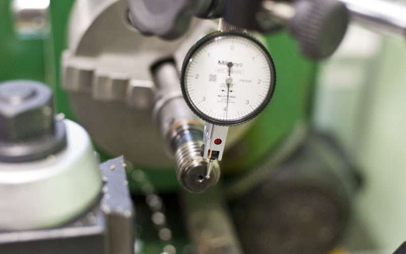
A quick test of the play in the bearings, looks pretty good.
Cut down the ballnut mount.
Forward travel:
Backwards travel:

All together about 8.5", which I consider about as good as I can get with two ballnuts down there.
Just out of interest I decided to check the backlash of the ballnuts. There is no spring in there yet so a single non-preloaded ballnut has about 0.0008" of backlash.
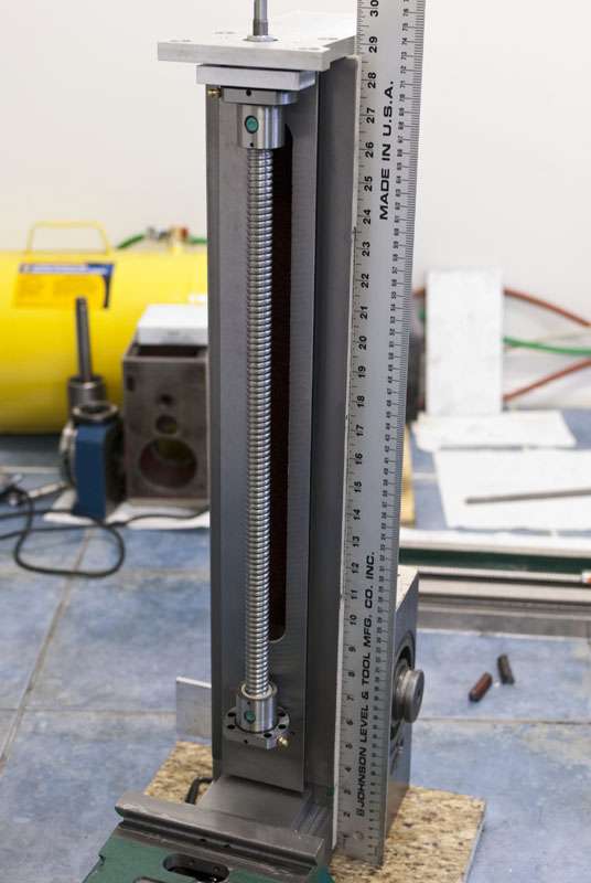
The Z axis is pretty much identical to the other axes.
Ballscrew mount. The larger bearings seem much easier to preload and feel a lot smoother as well.

Planning out the travel. I am expecting ~18"

Ballnut mount. Unfortunately it proved impossible to assemble a double preloaded nut inside the column so I ended up cutting it down and using a spacer.
Mill a couple inches out of the column.
Nut in the column.
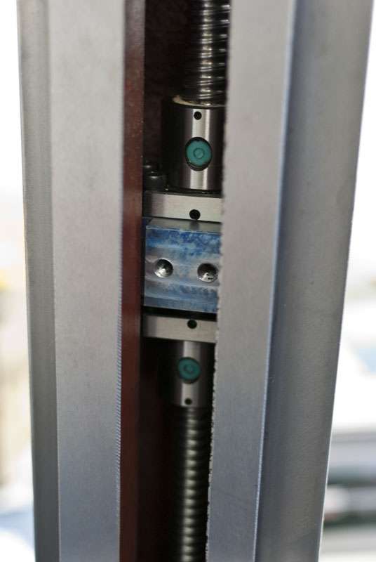
Spacer to attach z-slide:
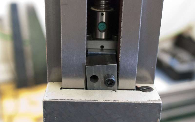
Nut with preload applied. The larger ballscrew can take way more load and I like it much better. About 150lb of springs here. Worth noting is that the preload is applied downwards, in the same direction as gravity.
Maximum travel upwards:
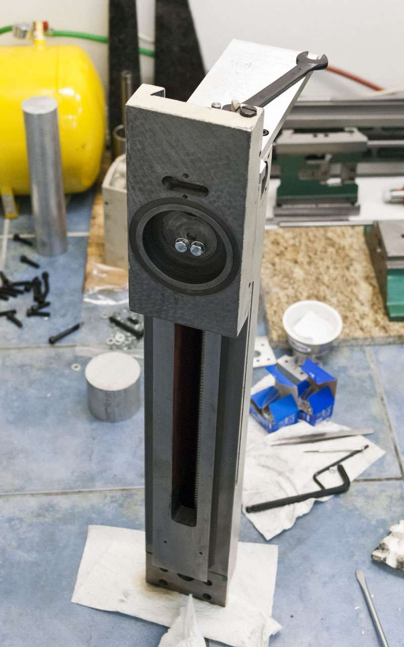
And downwards:
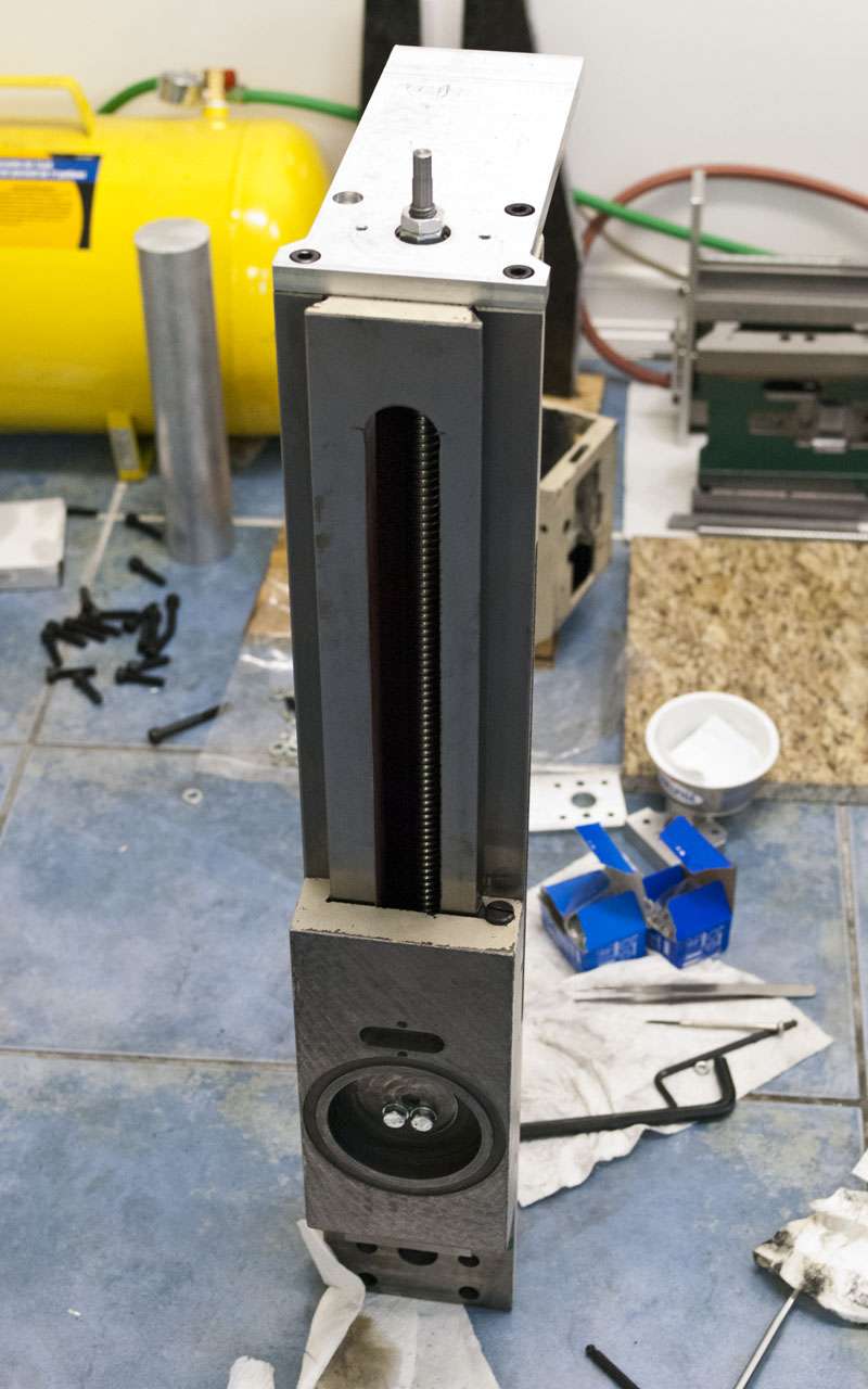
I ended up with a pretty ridiculous 18" of travel. I only cut about two inches out of the column as well.
So now all the screws are working. Next up is the 5th axis.
-
07-25-2012, 12:37 AM #49
Registered
- Join Date
- Apr 2005
- Posts
- 419
Since the question seems to have been coming up a lot, here is an error chart of a linearmotionbearing2008 rolled screw from china.
I measured 200mm of travel using a glass scale DRO (from thedrostore.com). I did my best to make the results as accurate as possible. I found the results surprising enough to do a second trial which has also been graphed. I had to guess the starting position for the second trial which is why they are slightly offset.
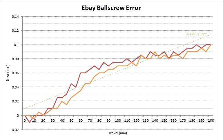
Extrapolated error is over 0.008" per foot, but the really interesting part of the graph is how the slope is not constant.
It seems to have been accepted that error in a ballscrew would be consistent over its length, and that it could therefore be corrected by changing steps/inch.
Apparently this assumption is not true for this particular screw since the error is concentrated in the first third of travel. Correcting a non-linear error like this requires screw mapping.
Note: I also measured 15mm of travel at 0.5mm intervals but was unable to detect any cyclic error with my glass scales (5um resolution).
Second Note: Despite the fairly impressive error, I still consider the screws a compelling option given their price.
-
07-25-2012, 03:00 AM #50
Registered
- Join Date
- Jan 2010
- Posts
- 251
voice of experience, thanks for sharing Originally Posted by 109jb
-
07-25-2012, 04:44 AM #51
Registered
- Join Date
- Apr 2005
- Posts
- 419
The control board I am using (KFlop) actually has provisions to automate the screw mapping process as well as correct in real time. Originally Posted by 109jb
If everything works as planned I should be able to achieve excellent accuracy with the ebay screws.
-
07-25-2012, 04:58 AM #52
Gold Member
- Join Date
- Feb 2006
- Posts
- 7063
Nice to see another KFlop user here! Originally Posted by 691175002
Regards,
Ray L.
-
07-25-2012, 06:32 PM #53
Registered
- Join Date
- Apr 2005
- Posts
- 419
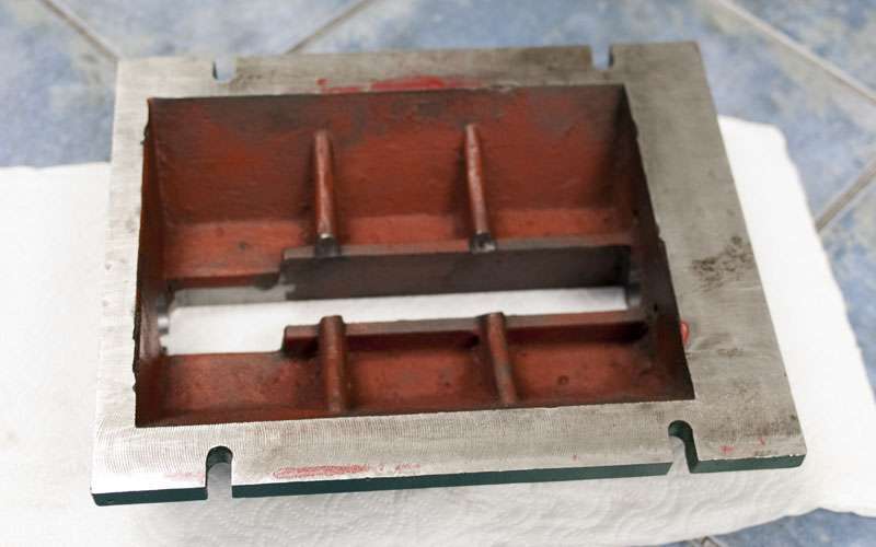
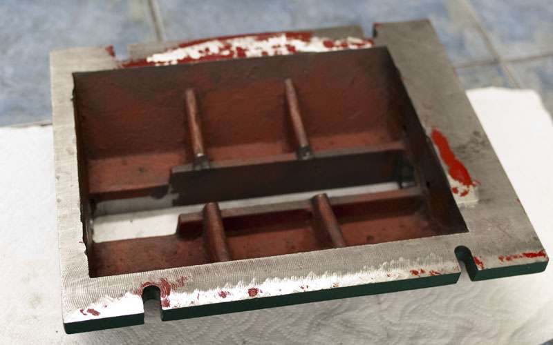
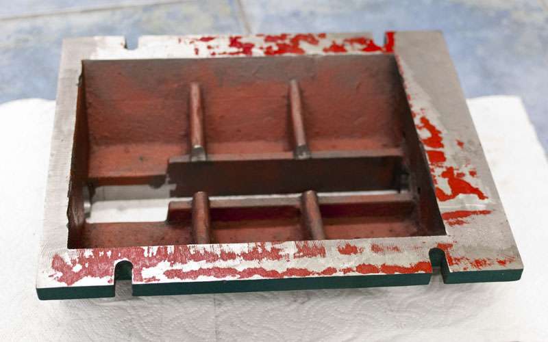
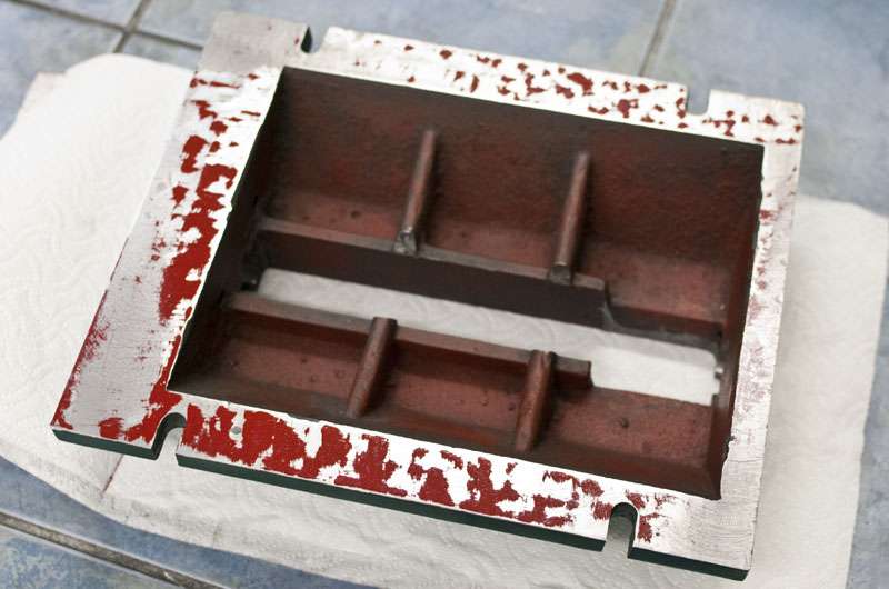
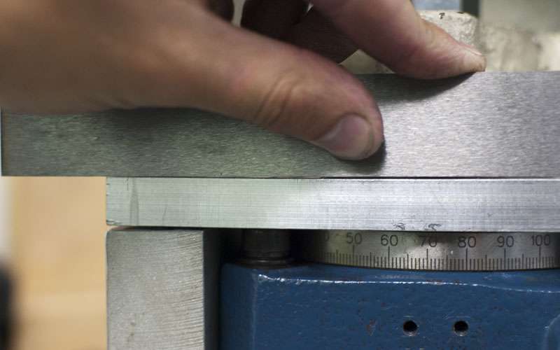
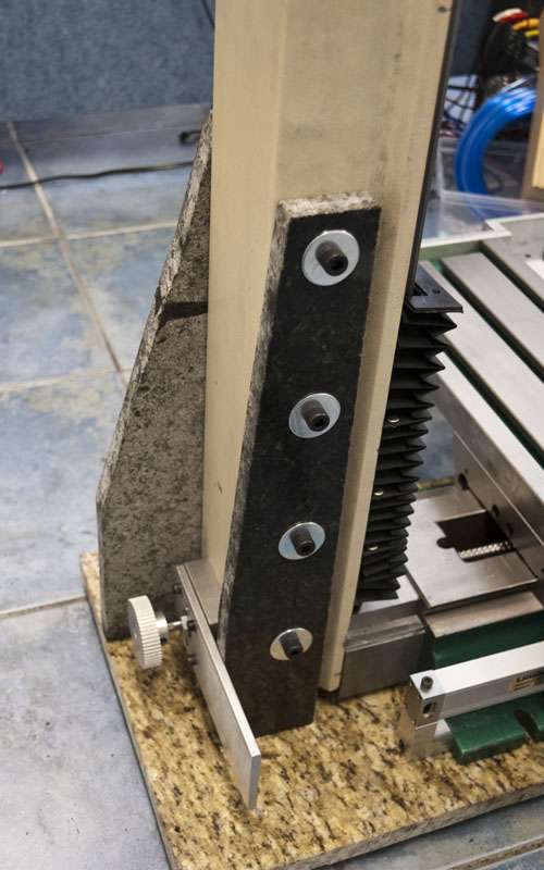
Normally you shouldn't bolt your mill to a rigid surface because the base of the mill is not flat. If I were to bolt my mill to the granite slab, it would bend the casting to match the granite.
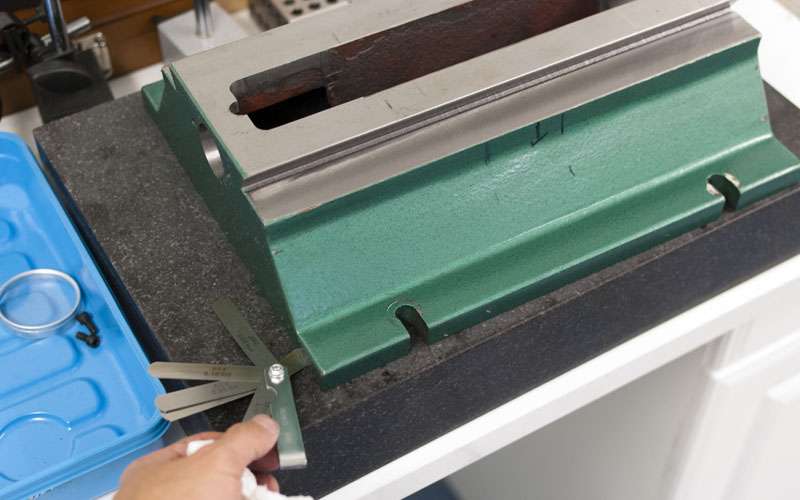
The feeler gauge shows some gaps. If the mill is bolted down like this, something will have to bend.
Since I need a rigid connection from the mill to the granite I decided to do a quick scraping job on the base of the mill.

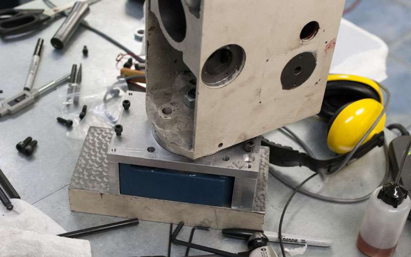
Anyways, time to talk about the fifth axis. A fifth axis is extremely dangerous in terms of accuracy because the errors get multiplied very quickly. One thou of play in the worm can become several times that error at the tool, and naturally a rotary table can never be as rigid as a block of steel.
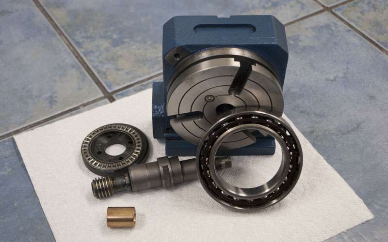
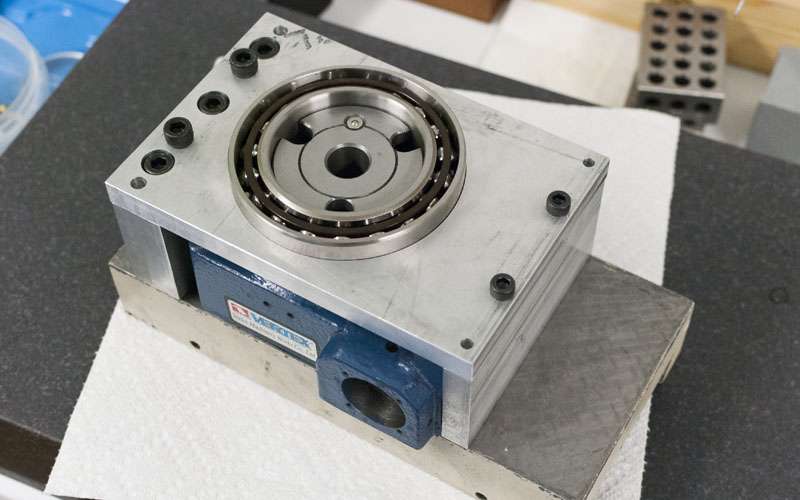
I chose to start with a 4" vertex rotary table for a few reasons. First, its width matches that of the column so I can make it look nice. Secondly, I have confirmed that it uses the same worm gear setup as the 6" table, and finally, vertex seems to have a reputation for being better than the average import.
The first step was to reduce play in the worm gear. In stock form, there are no bearings supporting the worm gear and there is a few thou of back and forwards play. Unfortunately, there is not enough room for A/C bearings so I had to use some bronze oilite thrust bearings.
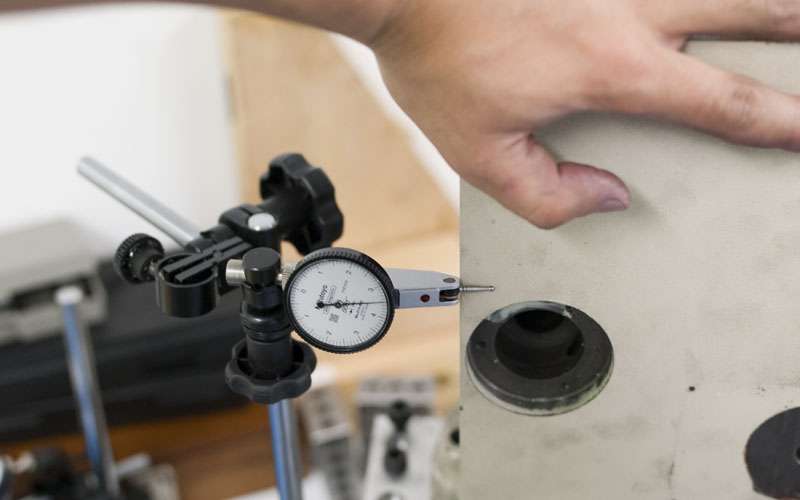
There is a very fine line between being tight enough and locking the worm gear, but with some care I can get the play into the tenths range.
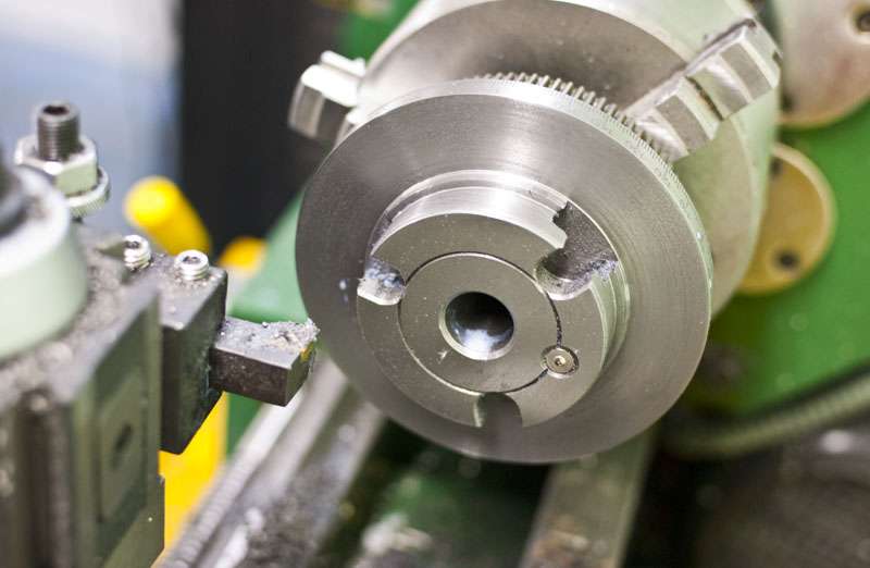
The second step was to machine down the table a bit.
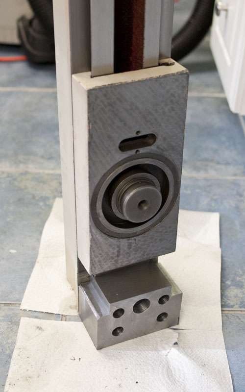
The table now fits under a 65mm ID AC bearing, and I have purchased a thrust needle washer for the reverse side. Both bearings can take a massive amount of preload.
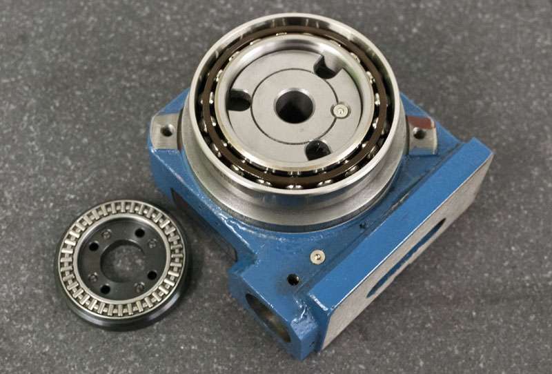
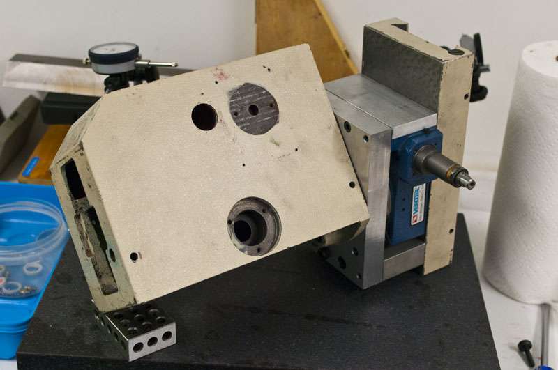
These pictures are slightly out of order but should convey the general idea. The load is primarily supported by the pair of bearings and the rotary table is used just for the worm gear.
Bolt goes through the back of the table.
Bearing and its mounting plate go over the front of the table.
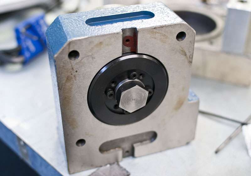
Mounted to the z-slide.
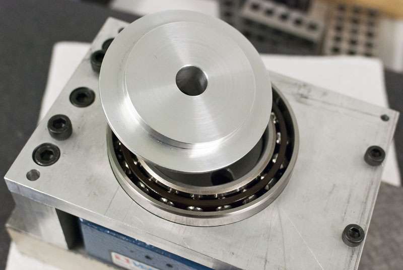
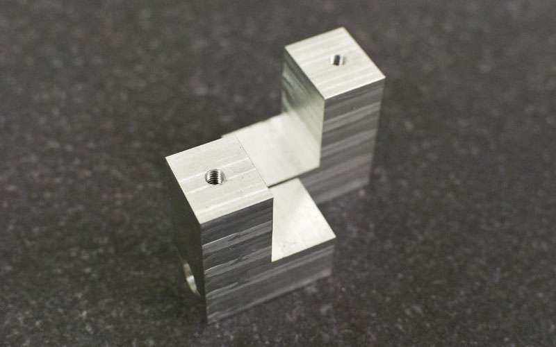
An aluminium spacer goes through the bearing and is bolted against the rotary table.
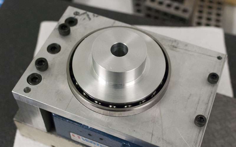
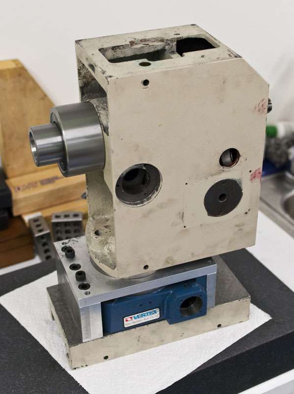
Head is bolted on top.
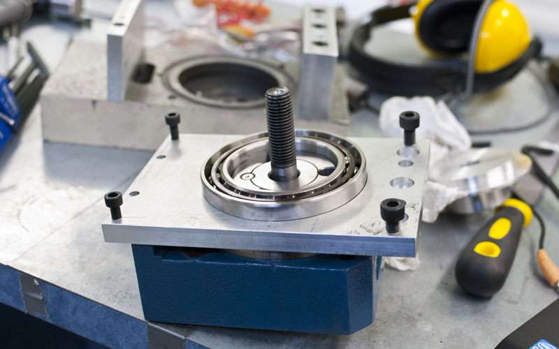
Unfortunately I can push the head around almost a thou by hand. There is just too much leverage.
The problem is also caused because I cannot apply sufficient preload to the bearings. The aluminium plate bends instead.
I finally bit the bullet and redid the plate with 1" aluminium:

Rigidity is much better but still not where I would like. I have ordered a few more parts before I call it finished.
On the plus side, it looks pretty awesome.
Just as a future note, if I ever build a mill from scratch I would try to design in room for a proper 5th axis that is built more like a spindle. I am starting to suspect you need a pair of tapered roller bearings to do this properly.
-
07-28-2012, 09:39 PM #54
Registered
- Join Date
- Jun 2011
- Posts
- 0
This is a fantastic build thread, and excellent photos too keep them flowing. You have put some serious work and effort into the scrapping and lapping and you're going to achieve machining tolerances which will far surpass what some of us (me included) can achieve........I may follow in your footsteps too........outstanding work well done and thanks for the detailed pics
 Eoin
Eoin
-
07-29-2012, 07:30 AM #55
Registered
- Join Date
- Apr 2005
- Posts
- 419
Thanks for the feedback, my thread has gotten pretty quiet after the first few days.
It is actually a little funny to think that I am already a few months into the build and I haven't even touched a stepper/servo yet. I've been serious about my build to this point, but now its the point of no return since the money has been spent.
Some quirk of the postal system managed to deliver all four packages on the same day.
Servos and KFlop:
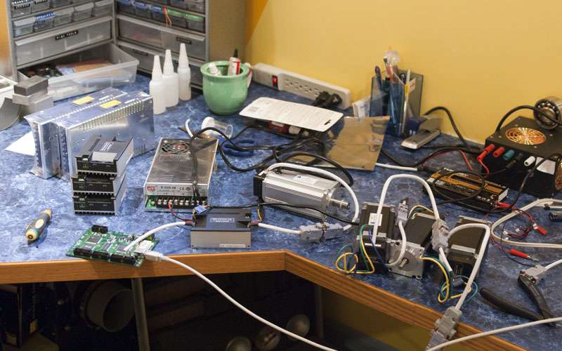
I choose to use DMM-Tech servos instead of stepper motors. Was a tough decision to make but I get a few minor advantages from the servos. I should be able to run about three times the acceleration of a stepper based system. Also, DMM servos use absolute encoders so I can get perfect accuracy out of my home switches very easily.
I choose a KFlop control board because it allows running closed loop with linear encoders which is pivotal to my build.
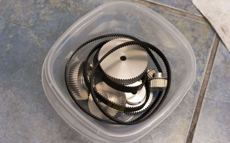
Got my pulleys from sdp-si as well. I suppose pulleys are pulleys, but I choose the GT2 tooth profile (with 3mm, GT3 belts) because they have extremely low backlash.
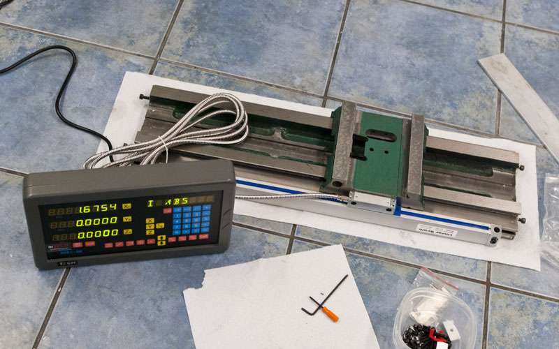
And the glass scales:

I ordered them from thedrostore and was impressed with how cheap they were as well as all the extra stuff they throw in. I actually got a full 3 axis DRO setup because it was cheaper than buying 3 individual scales.
The glass scales are pretty central to my build so I'll outline some of reasons behind the decision.
From one standpoint, adding glass scales to a mill is pretty magical. Because the glass scales are measuring the actual position of the table, any errors before that point can be corrected. Horrible ballscrews, backlash? No problem. It will even compensate for thermal error. Pretty much the only errors left over are from the geometry of the machine and scales themselves.
This sounds too good to be true, and it is. The drawback to glass scales is that even if you can measure an error, the machine will take a non-zero amount of time to fix it. If the mill detects backlash, it will require a tiny fraction of a second before the servo/stepper motor finally turns the ballscrew and the table finally moves.
The speed at which these corrections can be performed is limited by the rest of the system which is why I am focusing on low backlash and high acceleration in my build. The rate at which corrections can be performed is essentially known as the system bandwidth.
In the end we are essentially trading one error (backlash, ballscrews) for another (system bandwidth). The rational behind using scales is that I believe it is a cheaper way to get accuracy. A glass scale costs 160$ per axis, whereas the cost of using ground ballscrews and duplex pair bearings would be many times that.
Knowing the limitations of glass scales, how much do they improve accuracy? The simplest description is that as the toolpath becomes faster and more complicated, the scales become less effective.
Without finishing the mill and doing a through analysis it is impossible to say for sure, but I am confident that typical conversion feedrates and toolpaths will be no problem.
(The dynomotion site has some more information on control theory, I've not been entirely accurate in my attempts to describe the concepts. Bode Screen )
Anyways...
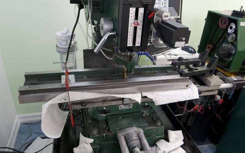
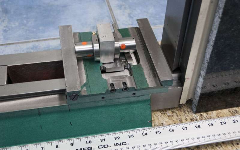
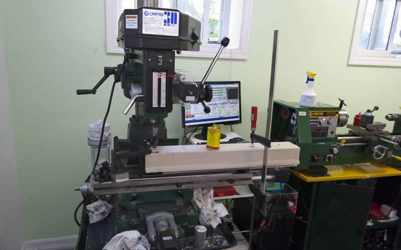
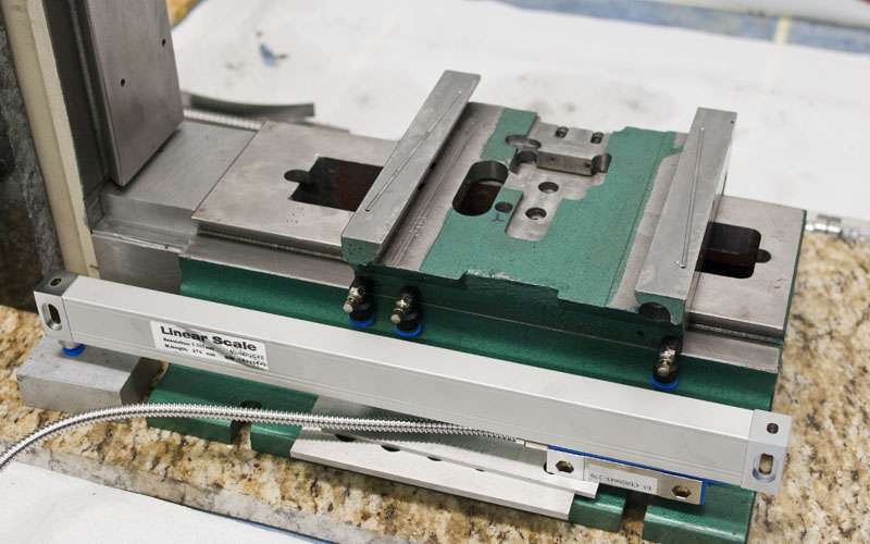
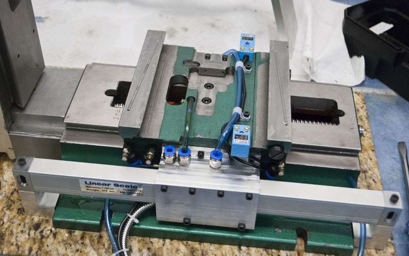
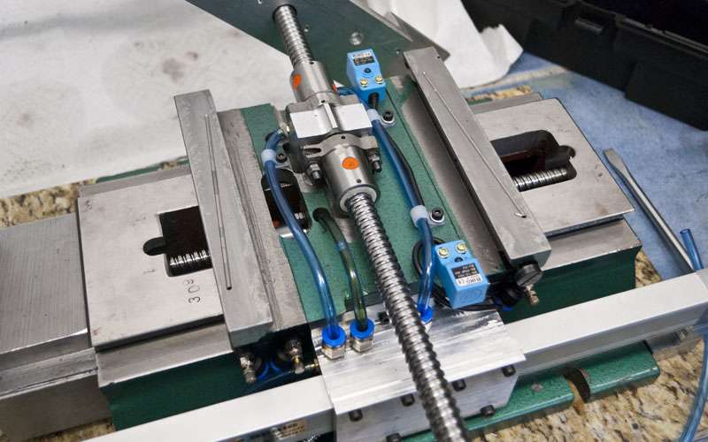
Attached a scale to the X axis and gave it a spin.
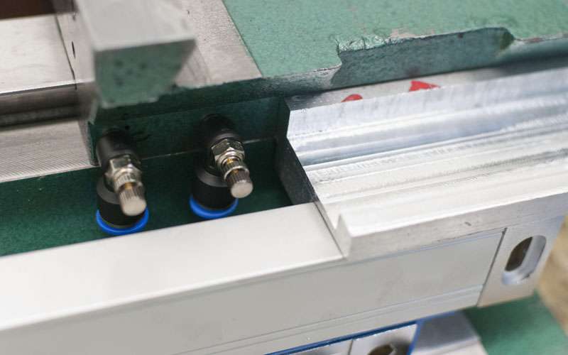
I also began work on the one-shot oiling system. It is pretty complicated. The goal is to have adjustable oil flow to every location that needs it. The system must also look nice and be out of the way.
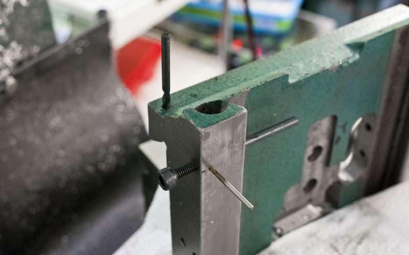
Here are the holes I ended up drilling for the X axis. The X axis DRO is in the way so I had to move the oil inlet to the bottom of the saddle.
I messed up machining one of the oil grooves. Was in g90 when I thought I was in g91.
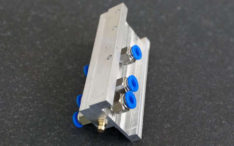
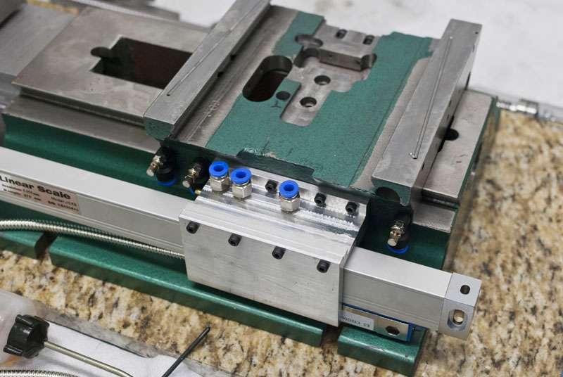
Oil distribution is combined with the Y axis DRO mount. It's pretty nifty.
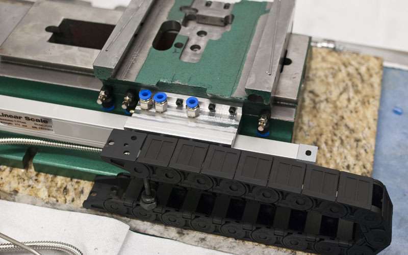
I will probably add some cable chain here later as well.
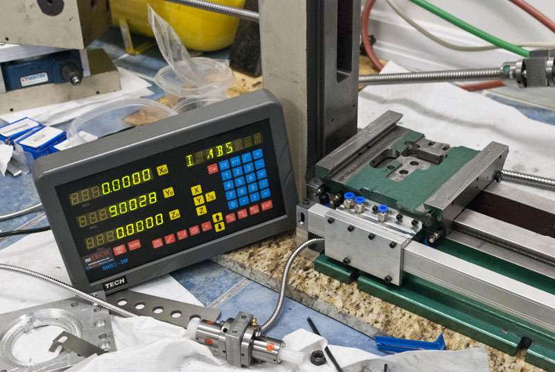
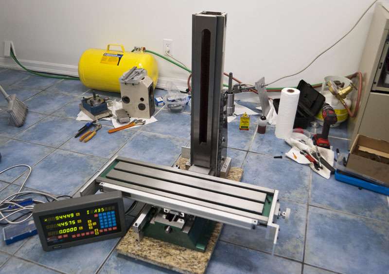
Testing out the DRO.
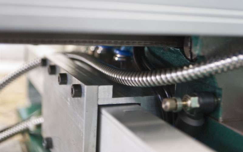
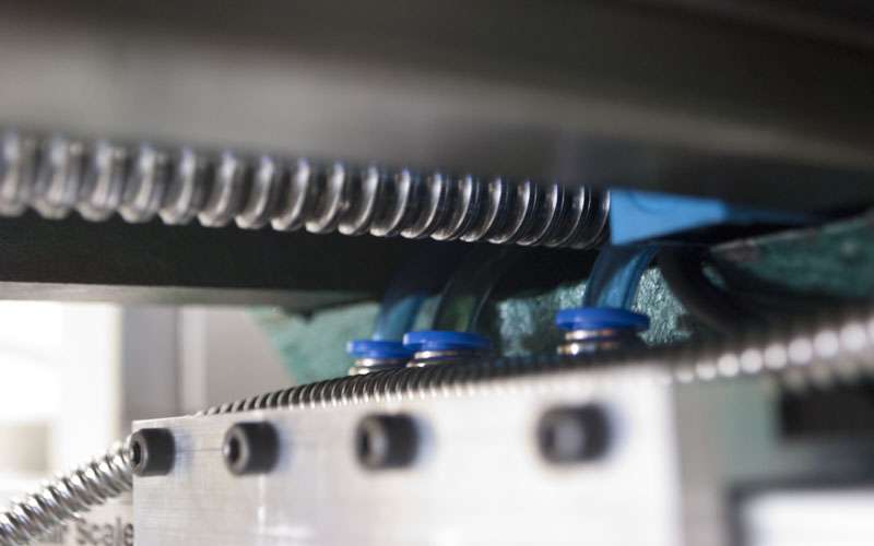
It looks neat in the pictures, but this was absolutely awful.
Seriously, the sheer amount of stuff underneath the table is ridiculous.

And the best bart is it all disapears.
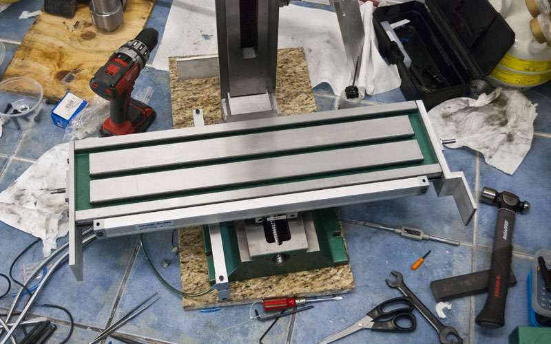
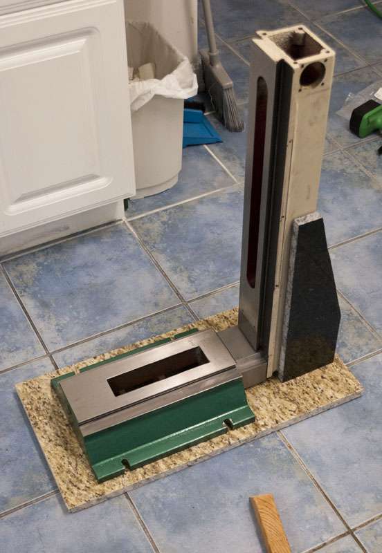
I finally bolted the granite onto the column.
I'm not actually sure if I am going to attach the three pieces of granite together. I feel like tramming is going to be near impossible if I do. I might just leave the granite there for looks (I suppose the weight might dampen vibration as well). I'll think it over later.
And done for now! Finally feels like I am really making progress.
-
07-29-2012, 07:19 PM #56
Registered
- Join Date
- Jun 2011
- Posts
- 0
Will you connect the linear scales to the servo drives as opposed to connecting the encoders or is there a way to connect the scales to Mach to input the absolute distance traveled.........I'm using steppers so this is all new territory for me.
Eoin
-
07-29-2012, 08:05 PM #57
Registered
- Join Date
- Apr 2005
- Posts
- 419
While you can plug the linear encoders into the servo drivers, doing so is likely to make the system unstable. Originally Posted by Mad Welder
You need to run both encoders simultaneously (one linear encoder on the table, and one rotary encoder on the servo).
Galil has a good video on it here: Tutorials - Galil: We Move The World
Mach3 is not capable of using encoders. I know that linuxcnc and kflop are capable, but I expect that setting it up will be fairly involved.
-
07-30-2012, 01:35 AM #58
Registered
- Join Date
- Feb 2012
- Posts
- 296
Progress looks great!
Where did you buy your fittings?
I am getting ready to put my last order in for my oiling system and have not decided on 1/4 NPT or 1/8 NPT yet but it looks like you used 1/8 NPT...not positive though it's hard to tell.
I think my next big task is to wrap my head around kflop as I would really like to implement glass scales into my built at some time. You did a great job convincing me!
Loving the build, the time really flies by doesn't it...?
-
07-30-2012, 04:37 AM #59
Registered
- Join Date
- Apr 2005
- Posts
- 419
I bought all the oiler fittings from Mettle Air: http://stores.ebay.ca/MettleAir?_rdc=1
I got the idea from someone on cnczone. The real stuff gets ridiculously expensive very fast.
Between the brass check valves that come with the ballnuts and the cheap fittings from ebay I'm only using about 60$ of stuff.
I went with 10-32 threads since I already had the tap.
-
07-30-2012, 04:41 AM #60
Gold Member
- Join Date
- Aug 2010
- Posts
- 630
How does the hose attach? Any idea how many PSI they can handle? Originally Posted by 691175002
Inner Vision Development Corp. - http://www.ivdc.com
Website Design & Development. Shopping Carts, SEO and more!

 Reply With Quote
Similar Threads
-
G0704
By kd4gij in forum Benchtop MachinesReplies: 8Last Post: 07-07-2016, 12:00 AM -
DRO for G0704
By UMR in forum Benchtop MachinesReplies: 4Last Post: 07-06-2016, 04:04 AM -
No Joy with my New G0704
By DogWood in forum Benchtop MachinesReplies: 5Last Post: 07-05-2016, 05:49 PM -
G0704... Yes Another One ;)
By ww_kayak in forum Benchtop MachinesReplies: 24Last Post: 05-27-2013, 03:47 PM -
G0704 or a X-3
By USN in forum Benchtop MachinesReplies: 8Last Post: 05-30-2011, 08:24 AM
