


Sorry, I was unclear as well. The paint is still on the casting. I intend to sand and repaint later though. I really have no clue how one goes about repainting a mill but I've heard stripping all the way adds a lot of work because there is a tonne of bondo on the castings.Originally Posted by doorknob

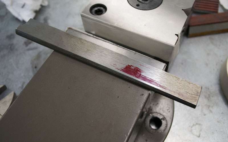
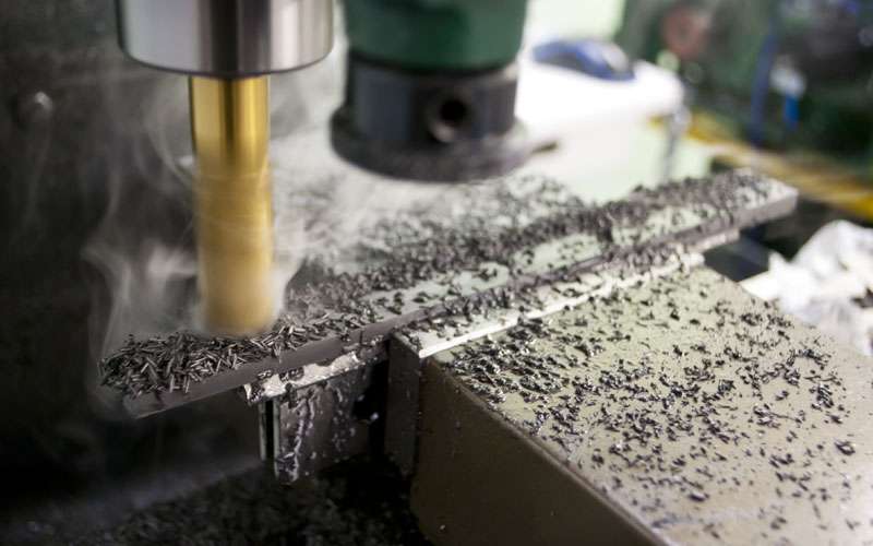
I bought a carbide scraper from Hand Scraping Tools . I did enough scraping that I consider the carbide worthwhile, but you have to make sure you have the equipment to sharpen it.
One mistake I made was getting only a single blade. Get at least one spare because you need different edges for different stages of scraping.
___
As I mentioned earlier, I wanted to do something minor to the gibs and then see if I could get a more reliable error measurement.
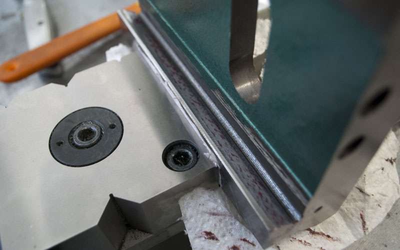
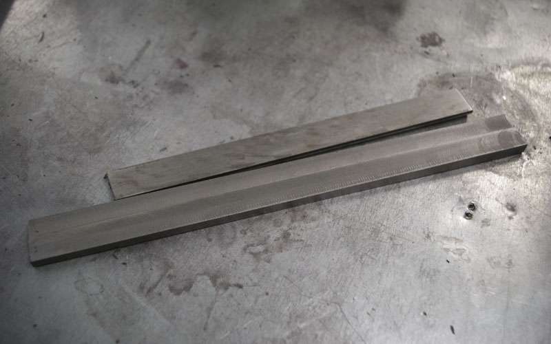
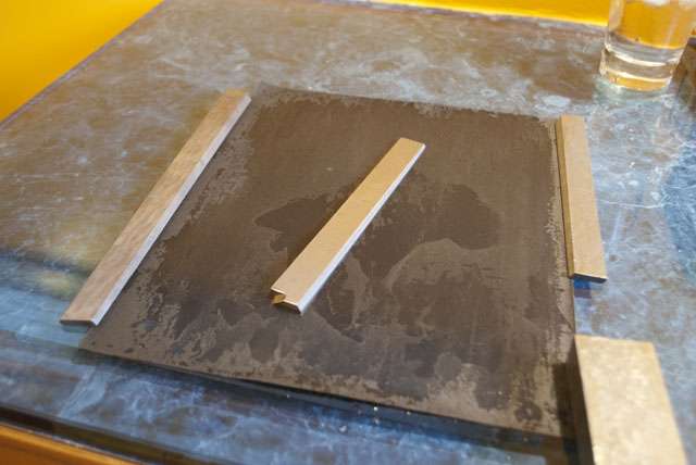
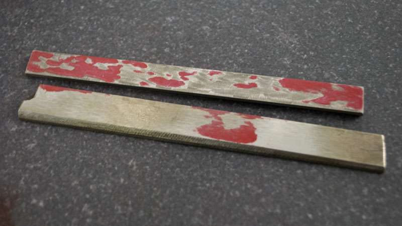
The most basic way to fix the gibs is sanding them against something flat. Almost anything will do, I used a piece of glass and a sheet of 400 grit wet/dry sandpaper.
This was a very simple job and if you compare the contact now to the original gib the difference is incredible. I didn't spend as much time as I could have, but make sure you leave a few bumps to hold oil.
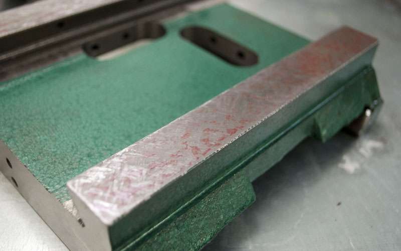
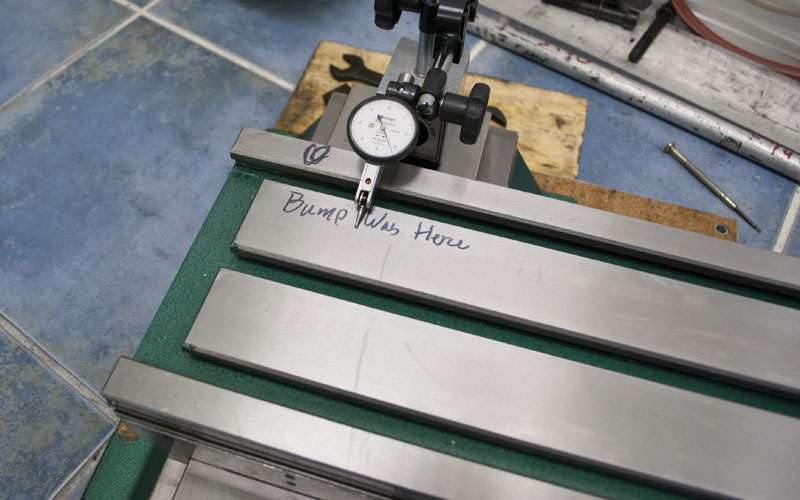
I also figured I might as well give the straightedge a go as well. The g0704 comes with milling marks left in the ways (for oil retention) but they are still fairly sharp out of the box. I just took a few swipes with 400 grit for fun.
_____
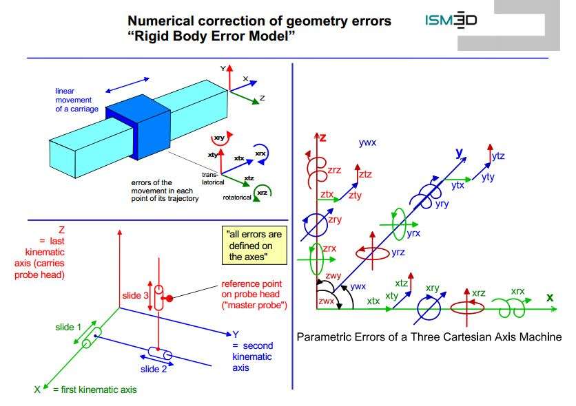
Before I focus on correcting the alignment errors in my g0704 it is a good idea to understand what errors can be present in a mill.
Accuracy is often quoted (or even measured) as a single number, but that is very simplistic. Almost all accuracy tests only measure a very small subset of the total possible errors.
Here is an official "Parametric Errors of a Three Axis Machine" chart, there are 7 errors per axis for a total of 21:
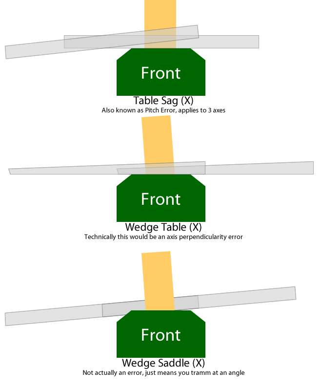
It isn't actually as complicated as the picture looks (Each axis has x,y,z, roll, pitch, yaw and linear error) but I've made a quick diagram for the most common errors.
Table sag tends to be the largest error because of the design of most hobby mills. When you move the table all the way to one end, it has tremendous leverage on the saddle and if there is any looseness in the gibs the center of the table will lift. You also start cutting at an angle; this is a pretty nasty error and very hard to eliminate.
I've coined the term wedge table because it exists on my mill. This is actually axis perpendicularity (or Z error in the X axis).
A wedge saddle also exists on my mill. It does not actually cause any error because you can tramm the column to match.
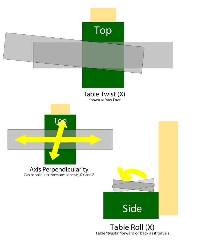
Table twist is fairly straightforward.
Axis perpendicularity is also fairly straightforward. Some axis perpendicularity errors are easily fixed (column tram) whereas others are a result of machine geometry (x/y perpendicularity).
Table roll is kinda like table twist just in a different axis.
Note that if all the sliding surfaces of a machine are perfectly flat, parallel and perpendicular where they should be the machine will have no errors. If you can verify that the alignments in the machine are correct there is no need to measure the resulting errors (or lack of errors).
____
Because the ground surfaces (aka the dovetail ways) all appear to be relatively true, I will assume they are perfect until proven otherwise. Scraping the ways will be a tremendous amount of work and I would probably need both a larger surface plate and a larger straight-edge.
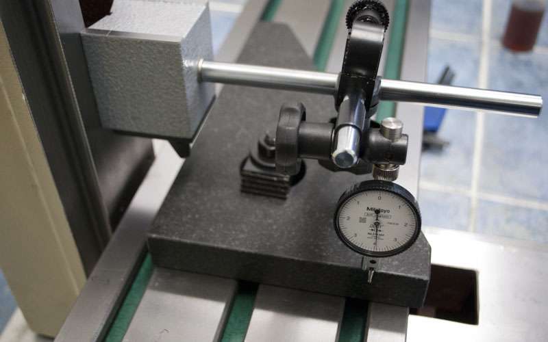
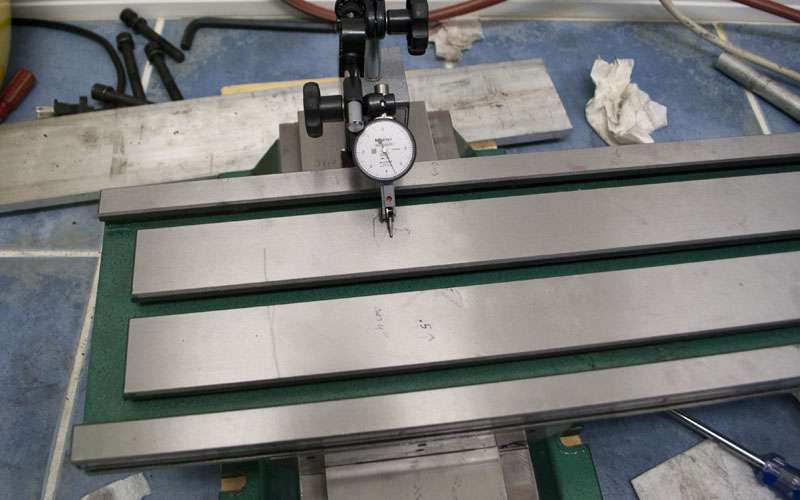
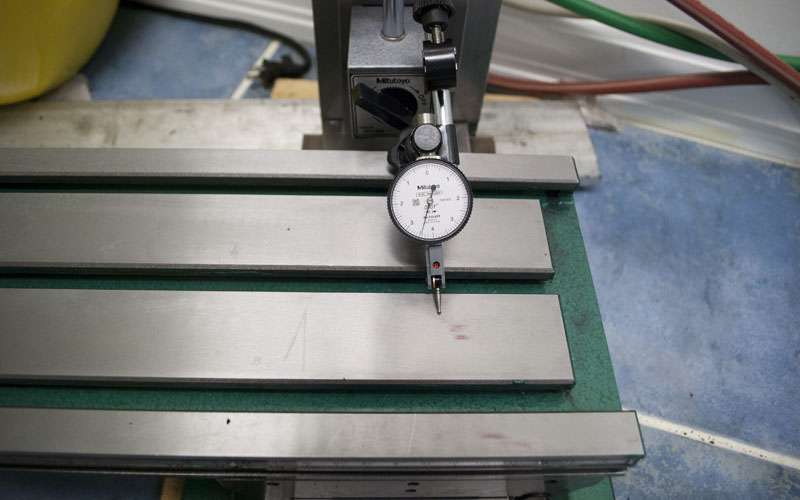
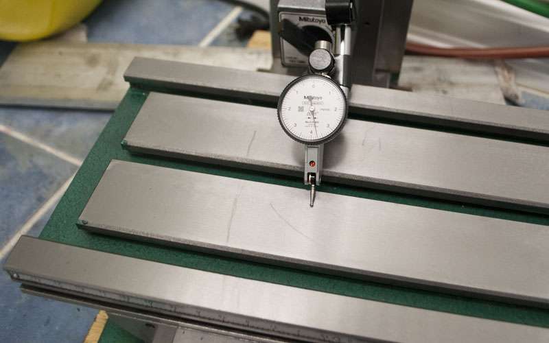
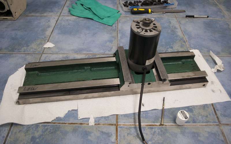
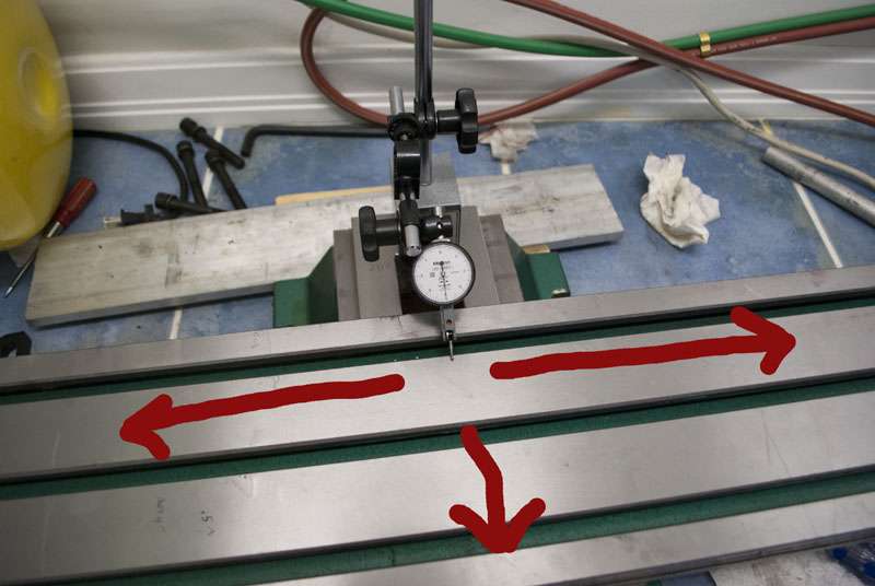
To start, I will focus primarily on measuring table sag by putting an indicator on the table and sliding the table back and forth.
Table sag is basically an easy way to measure any looseness/poor fits in the mill. Here is a comparison of the errors before and after lapping the gibs:
- Flex: 0.003" -> 0.001"
- Table Sag (2" from ends): 0.002"->0.0015"
- Sag (At end of travel): 0.004"->0.002"
It was fairly easy to feel the difference when adjusting the gibs as well. Before it was either loose or locked whereas now there is more of a sweet spot.
Right now the flex still left in the machine still masks any other errors so I will start scraping.
____
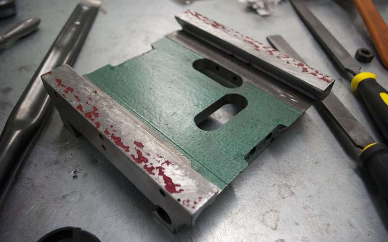
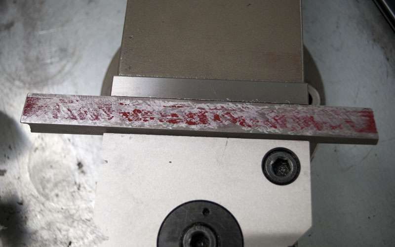
The idea behind scraping is to cover a reference surface with a very thin layer of ink. You then rub the workpiece against the ink and it will transfer only to the points that touch. You want as much contact as possible between the two surfaces so you scrape off the high spots (where the ink has transfered) and repeat.
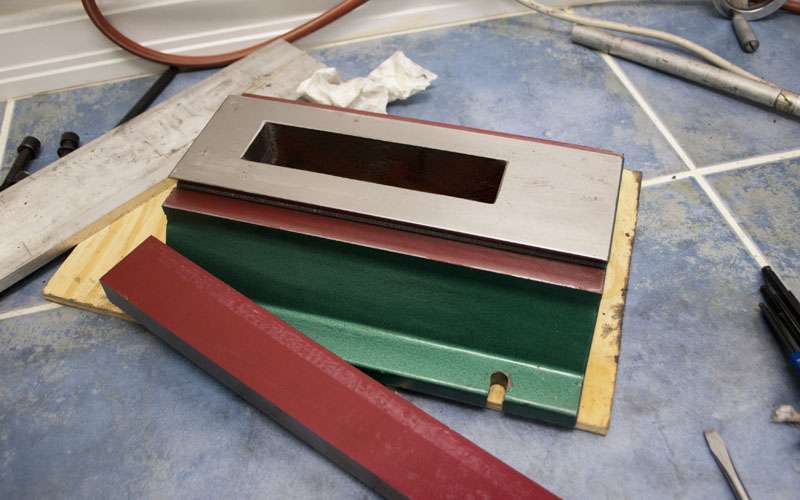
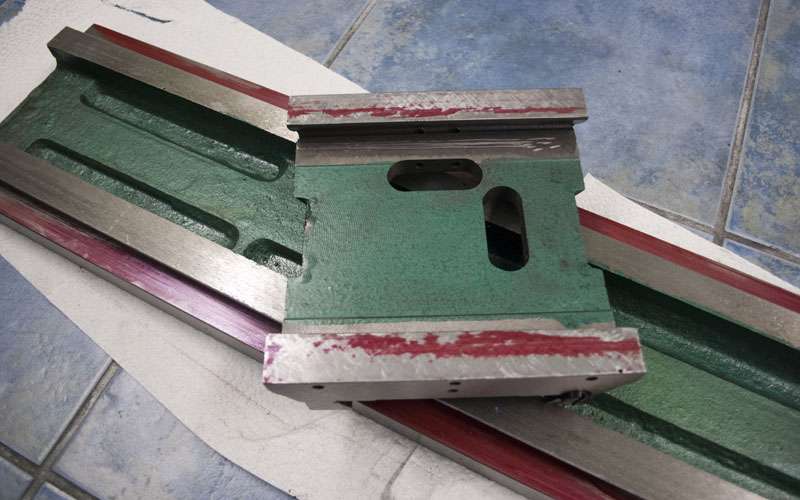
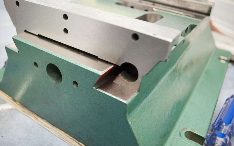
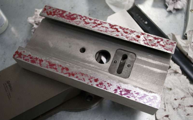
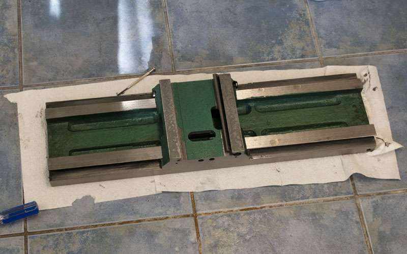
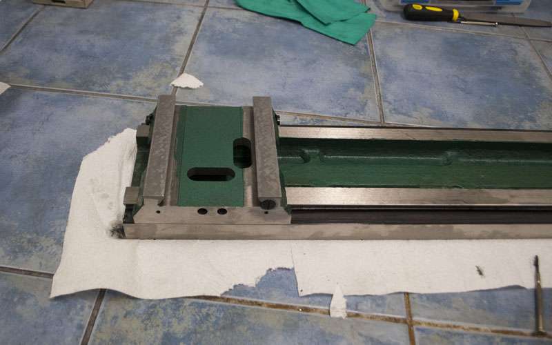
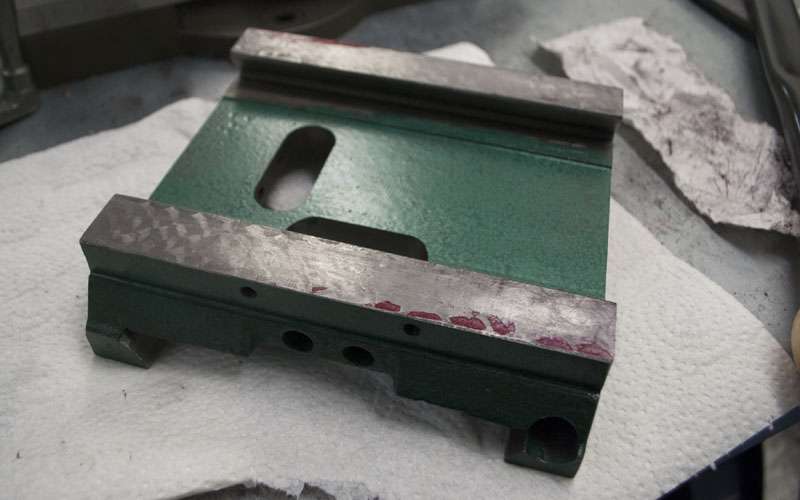
The first surface I will be scraping is the bottom of the saddle. I have chosen to start by scraping to a surface plate since that is easiest to spot off.
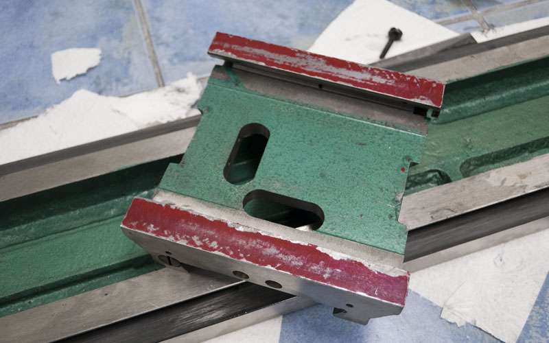
This is the saddle in its original state. Consider that all the forces the mill is under are being transfered only by the inked points. The rest of the iron is pretty much just hanging around.
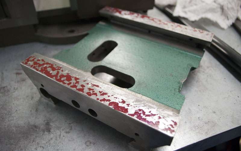
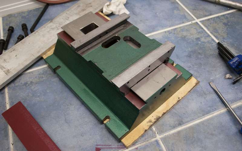
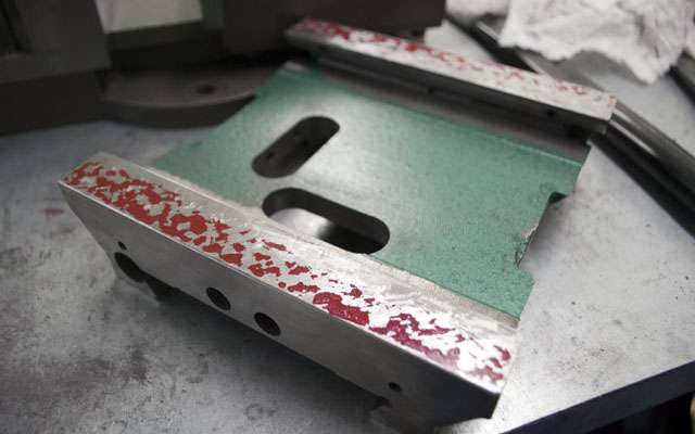
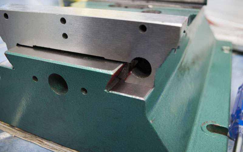
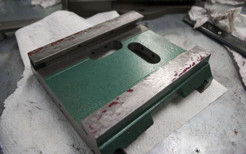
A bit of scraping, there still isn't that much contact but now the entire surface has high spots instead of just two corners.
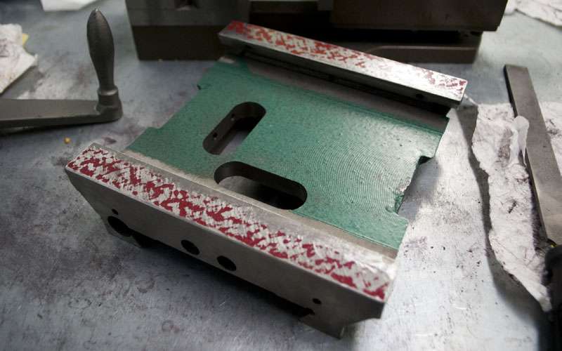
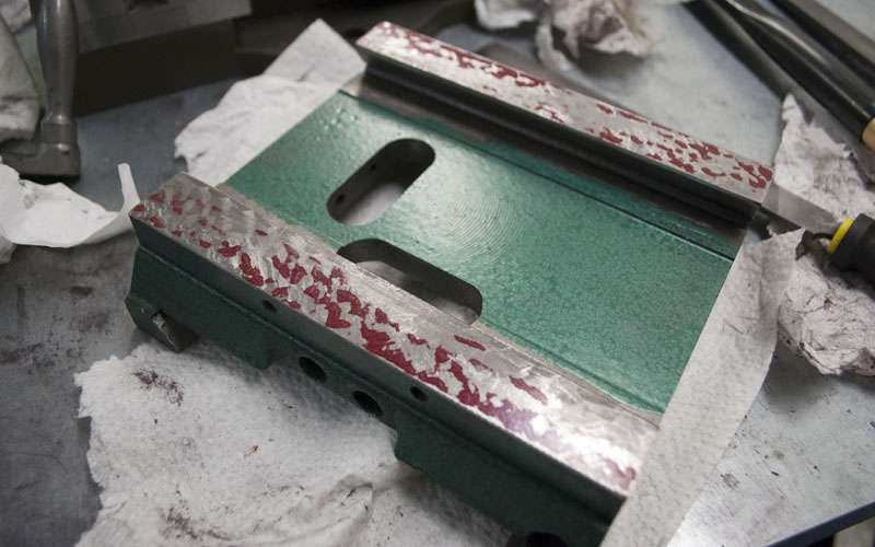
Getting closer. The process slows down a lot as you get further along because there is so much more material to remove per step.
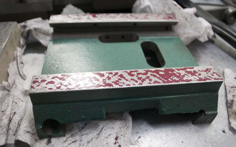
And done for now. This surface has not yet been finished but I am putting that off for later.
Thread: Ryan's g0704...
Results 21 to 40 of 284
-
07-03-2012, 07:14 AM #21
 Registered
- Join Date
- Apr 2005
- Posts
- 419
-
07-03-2012, 12:56 PM #22
Registered
- Join Date
- Feb 2012
- Posts
- 296
Wow thanks a ton for all the pictures, diagrams, and detailed info!
You are going to greatly help a lot of people, like myself, who are very new to these machines.
What kind of tolerance are you aiming for once you are all done with everything? Do you want to be able to hold a thou or two? I am hoping you don't have to do all that work to hold five thou.
-
07-03-2012, 02:59 PM #23
Registered
- Join Date
- Jan 2005
- Posts
- 1943
For those who want a cheap scraper set, you can get them at Grizzly for $8.50
T10086 3 Pc. Machinist's Scraper Set
-
07-03-2012, 05:59 PM #24
Registered
- Join Date
- Apr 2005
- Posts
- 419
I'll use numbers that ignore the last few inches of X travel, since the ends of the table are rarely used and doing so more than doubles the total error. Originally Posted by DRock
I think a stock g0704 can hold to 0.002" per foot for each axis as long as the gibs aren't completely messed up (and the column is properly trammed).
You can then add in your backlash/leadscrew error which will be about 0.002" (backlash+slop after compensation) + 0.002"/Foot (leadscrew pitch error) depending on how you set up the machine.
These are pretty much just guesses, but the total error would be 0.002" + 0.004"/foot (per axis) which seems reasonable.
I think an ambitious goal would be a geometry error of 0.0005"/Foot. With glass scales I should have zero leadscrew pitch error and backlash/slop should be around 0.0004".
This comes to 0.0004" + 0.0005"/foot per axis.
Of course, in this range you need to start worrying about thermal expansion and machine rigidity so I don't expect to hold that in a cut.
I'm also just guessing numbers. I don't actually know how this will turn out.
-
07-03-2012, 07:01 PM #25
Registered
- Join Date
- Aug 2010
- Posts
- 278
I actually have that grizzly set, the tools are a little small (special the flat scraper), you can not apply a lot of pressure to remove material. That's why i will be changing to one of these Anderson 5 Tube Scraping tools. The set is OK for doing a small job, but you will be scraping much longer, for a beginner it will do the job. Originally Posted by 109jb
Hive 8 - G0704 CNC Mill - 20 inch Telescope - High Resolution 3D Printer - Lasersaur 100W CO2 Cutter / Engraver
-
07-03-2012, 08:28 PM #26
Registered
- Join Date
- Feb 2012
- Posts
- 296
Thanks for the quick reply!
So basically you scrape for alignment and smoothness of operation and not so much for tolerance.
I am definitely going to fix my gibs and possibly do double preload nuts on both axis which will hopefully bring my tolerance close to.004" per foot which would be fine for what I intend to use it for.
I am looking forward to seeing more progress and pictures!
-
07-03-2012, 11:28 PM #27
Registered
- Join Date
- Apr 2005
- Posts
- 419
You are absolutely right, to a large extent the smoothness of motion is more important than absolute alignments. If you can measure an alignment or linear error that is repeatable, it can always be corrected in software. On the other hand, if your mill moves 0.004" when you drop a vice on the table you are screwed no matter how much work you put into everything else.
As an example, "head nod" and table sag are two very annoying (and large) errors that are caused almost entirely by poorly fit gibs.
http://www.cnczone.com/forums/bencht...nal_sag_x.html
Mill gibs tightening - The Home Shop Machinist & Machinist's Workshop Magazine's BBS
In this case I would say 90% of these errors can be attributed to poor fit, and at most 10% to underlying geometry problems.
-
07-06-2012, 02:23 AM #28
Registered
- Join Date
- Apr 2005
- Posts
- 419
I've continued scraping the saddle, this time fixing up the X side.
Since the Y side has been scraped flat, now it is time to worry about alignments.

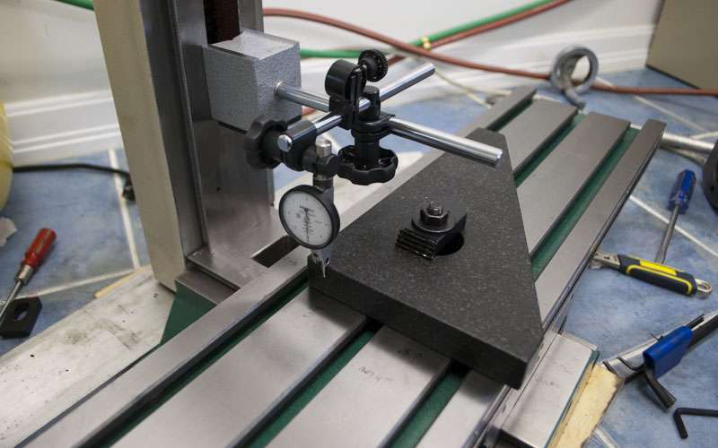
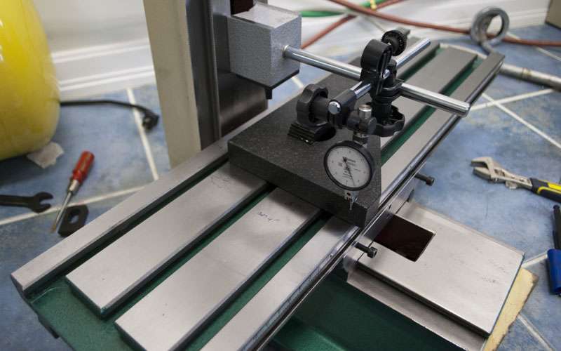
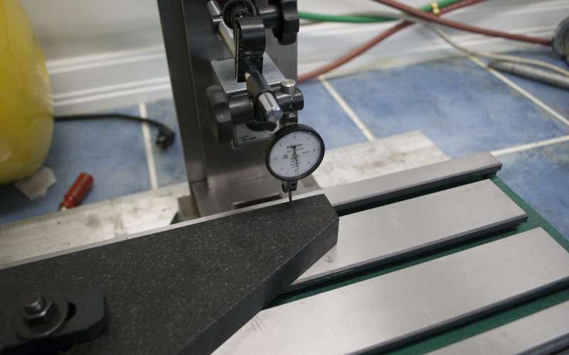
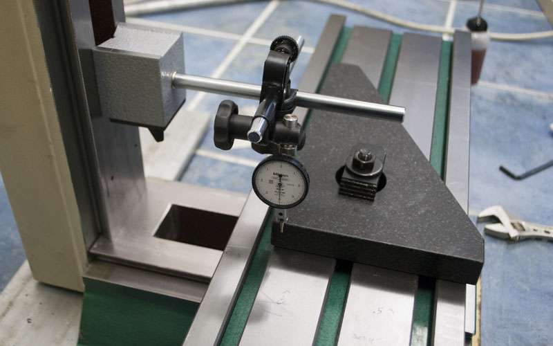
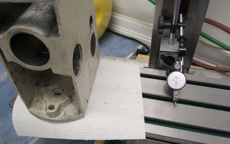
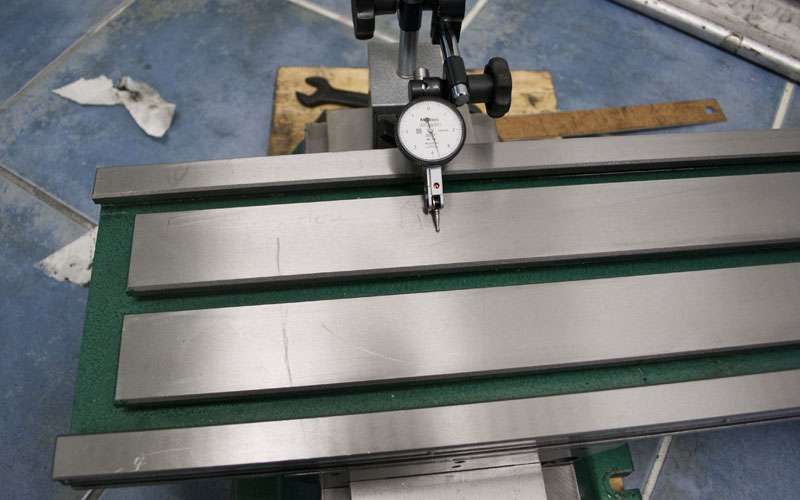
By sweeping an indicator around the corners you can determine exactly how low or high a given point is. Ideally the two sides of the saddle should be completely parallel and the indicator should remain at 0 at all points.
Here are some in progress scraping pictures, its all pretty much looks the same. This is a little more intricate though since I am trying to remove more material from the areas which I determined to be high. It is worth rechecking with an indicator along the way as well.
It is worth noting that the inside of the saddle is very low and only the outer 75% is spotting. I figured that is probably enough for now, I can go back later if it needs more scraping.
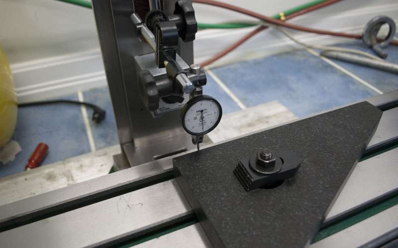
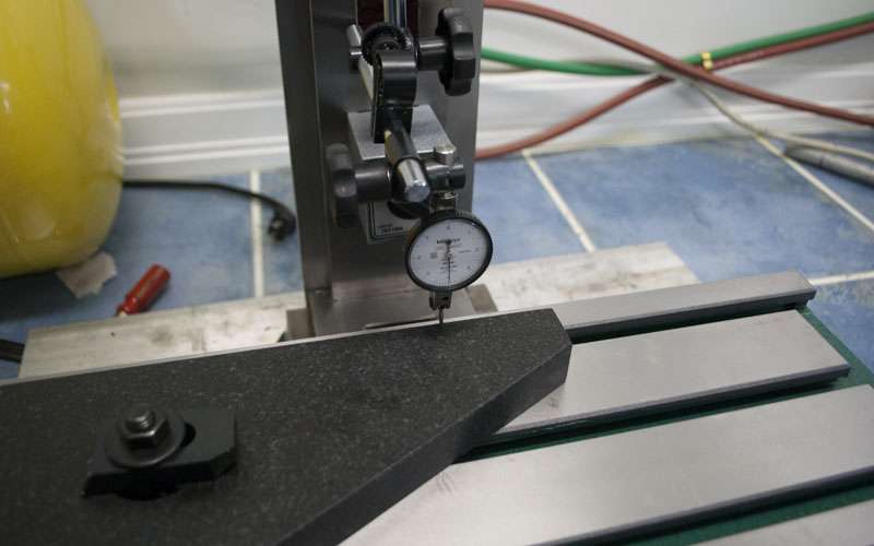
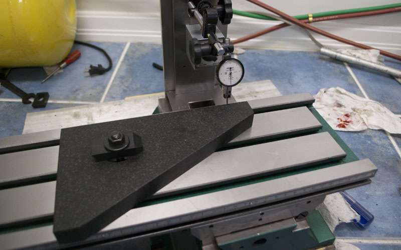
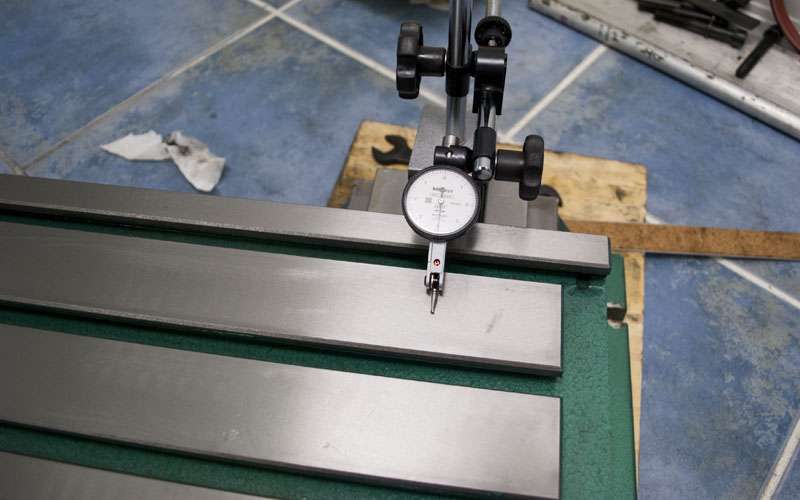
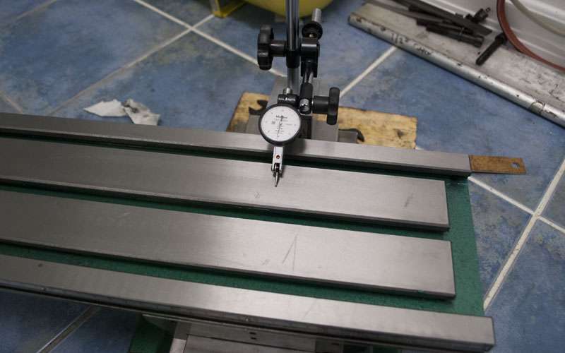
The scraping combined with lapped gibs did a fairly good job so I decided to take a look at axis squareness.
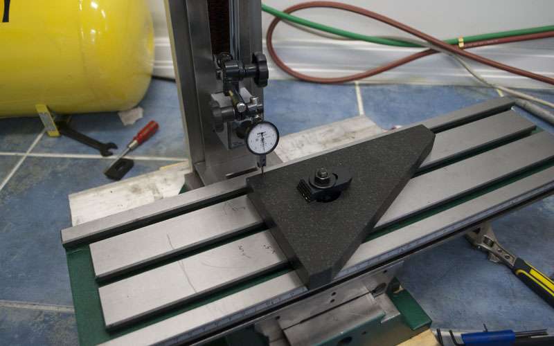
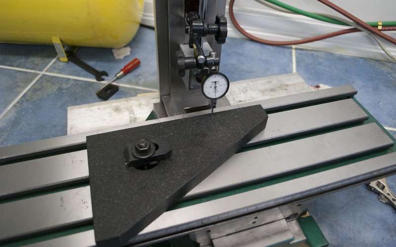
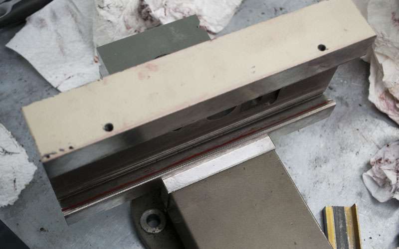
Align the square with the x axis...
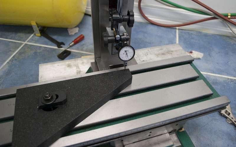
Whoa, that is not supposed to happen. Probably some twist going on with the table near the ends.
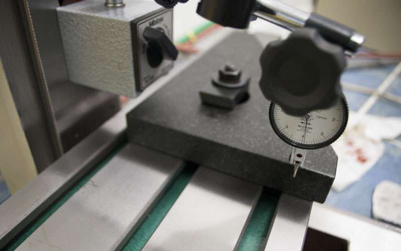
And check the squareness...
Out about 1 thou per foot, not particularly good or bad.
The x and y axes are misaligned which means that I am going to need to scrape the dovetails. To measure axis squareness (and dovetail angle) without reassembling the table would require at least a few days worth of scraping gauges and making measuring setups.
I will probably skip all that and reassemble the table to check squareness, the chances are the mill will be taken apart and put back together quite a few times anyways.
-
07-06-2012, 09:26 AM #29
Gold Member
- Join Date
- May 2005
- Posts
- 3920
I'm not sure about the usage of terms here.
Alignment is huge but without a well fitted up machine you will not be able to hold precise tolerances. Originally Posted by DRock
0.004" could be considered pretty terrible in some places. However you need to separate lead error, on the leadscrew, from basic mechanical error.I am definitely going to fix my gibs and possibly do double preload nuts on both axis which will hopefully bring my tolerance close to.004" per foot which would be fine for what I intend to use it for.
Yes I really like the posts and pictures. So far he is on the right track and things look really good; he should have a nicely functioning machine when done.I am looking forward to seeing more progress and pictures!
-
07-08-2012, 01:15 AM #30
Registered
- Join Date
- Apr 2005
- Posts
- 419
So the only way to correct the axis squareness is to scrape the dovetails.
I have to be very careful when scraping this surface because I have no way of verifying the angle, or squareness of the dovetails. I could spend a few days scraping fixtures and gauges that would allow me to make those measurements, however I've decided to just finish the scraping against the way itself. Note the gib side of the dovetail does not need to be scraped since it is not a sliding surface (although having it flat would improve gib performance so I'll give them a few passes).
I need to remove about 2.5 tenths from the high side of both the x and y dovetail to get my axes square. This isn't much material so I will consciously take slightly deeper cuts on the high side and then check as I go along.
Since I don't want to remove too much material I stop at around this point. It is pretty far from finished, but it is much flatter than it used to be and hopefully I successfully removed the 2.5 tenths I need to make it square.
Here is the other side of the dovetail after scraping.
And the results:
Much less twist at the ends.
And by some stroke of beginner luck I got it almost spot on in one shot.
In terms of other measurements, the combined lapping of the gibs as well as the scraping of the saddle makes everything slide better. Flex now measures ~2 tenths (0.0002") in the middle of the table to 5 tenths at the edges. The grinding on these machines seems okay, its just the the saddle and gibs which mess everything up.
Also worth mentioning is that since I am just pushing the table around by hand it is fairly easy to feel the difference. The motion feels much smoother.
-
07-08-2012, 02:11 AM #31
Erfahrener Benutzer
- Join Date
- Feb 2012
- Posts
- 234
awesome pictures. the squaring of the saddle is what really confuses me and has kept me from trying scraping. I really need to find a way to make or buy a jig for the dove tail spotting like yours. but i unfortunately do not have an extra mill and the cast iron camel back straight edges cost a fortune. Please keep up the great work my new g0704 comes monday and I cant wait to try to replicate what you have done.
-
07-08-2012, 02:48 AM #32
Registered
- Join Date
- Apr 2005
- Posts
- 419
The straightedge makes it faster, but it is actually more accurate to use the surface the dovetail mates against. Just apply the spotting ink to the ways on your table/base and rub the saddle back and forth to see where the surfaces touch. Originally Posted by Whizbang
I end up doing that later to finish the scraping.
-
07-08-2012, 04:37 AM #33
Gold Member
- Join Date
- May 2005
- Posts
- 3920
Back in the day we called that marrying the saddles to the ways.
Ultimately best mate up is had by fitting the saddle to the ways. Originally Posted by 691175002
I can see from where you are in this process that you will have a machine operating far beyond it factory capability. Further everybody following the thread will better understand why industrial machines are so expensive. It takes a lot of effort to assemble a machine to the precision you are going after here.
-
07-08-2012, 12:27 PM #34
Erfahrener Benutzer
- Join Date
- Feb 2012
- Posts
- 234
but then how did you establish which side needed scraped more to become square? Originally Posted by 691175002
-
07-08-2012, 07:45 PM #35
Registered
- Join Date
- Apr 2005
- Posts
- 419
The straightedge is used mostly for spotting with the ink. Alignment was done with a square.
Squares are a lot cheaper than straightedges but you have to watch the tolerances on them. Most machinist squares are only good to a thou a foot.
-
07-09-2012, 11:18 PM #36
Registered
- Join Date
- Apr 2005
- Posts
- 419
Time to start scraping the saddle to the ways.
First step is to get ink in the dovetail, it is kinda a pain to get a thin and even layer. I ended up using the straightedge to help a bit.
I then slid the saddle back and forth a few inches to transfer the ink:
The Y axis on the saddle looked almost bang on which means the ways were ground extremely flat and coplanar. Here is that surface after a few more passes of scraping. Once you start using thinner layers of ink it is harder to see the pattern:
The dovetail wasn't as good, the spotting indicates that it was cut at the wrong angle.

After some scraping:

It still needs more work but I want to scrape slowly so I have time to measure as I go.
The X axis:
This is a lot worse. If you compare this spotting to the original spotting off a surface plate it is fairly easy to see what is wrong:
The ways on the X axis are not coplanar so scraping to a granite surface plate wasn't really helping that much.
At this point my options are to scrape the X ways coplanar, or just scrape the saddle to fit the table. Scraping the x ways is the preferred solution, but it would be a ridiculous amount of work (and I would have to buy a 24" surface plate and scrape a new straightedge).
I decided to just scrape the saddle to fit and see what happens. From the measurements I've taken the ways should sill be flat and aligned, they are just slanted inwards.
The dovetail wasn't that good either but I'll be scraping more later.
Results to date:
Only a few tenths of table sag.
No more twist in the x axis.
Axis parallelism is still out one tenth but TBH it is very hard to measure such a small error in a repeatable fashion.
-
07-14-2012, 06:43 AM #37
Registered
- Join Date
- Apr 2005
- Posts
- 419
Finished off the dovetails in the saddle:
Much nicer spotting.
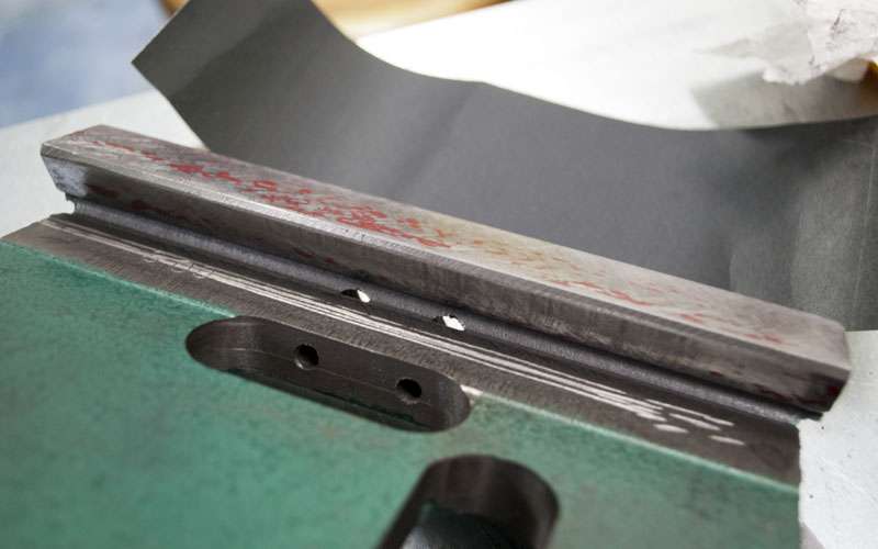
Last up is the gibs, the best way to spot gibs is by covering the corresponding surfaces with ink and pushing the gib in. This is a major PITA because you have to make sure the layers of ink are even but it tells you for sure where gibs are making contact.
Surfaces inked...
Gib knocked in...

Spots okay, the gib was lapped earlier and it shows.
Back of the gib is bad.
When you do a lot of scraping (material removal) the gibs end up too thin. I briefly considered making new gibs but decided it would be too much work so I shimmed instead. The picture is nice though.
Scraped gib.
Results:
Less than one tenth deflection.
About 4 tenths at one extreme.
Three tenths on the other side. The table is tight on this side and I cannot make use of the last two inches of travel. I will look into this later.
Gibs have been shimmed to the correct thickness.
Z axis after scraping.
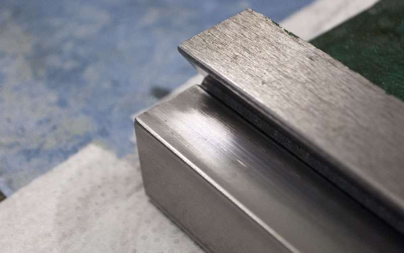
The dovetail before scraping. It is making only line contact which means it was cut at the wrong angle.
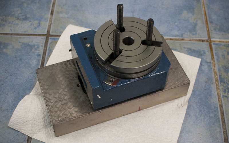
Just tossing ideas around for the 5th axis, I will be implementing something far more rigid than this.
-
07-16-2012, 05:08 AM #38
Registered
- Join Date
- Apr 2005
- Posts
- 419
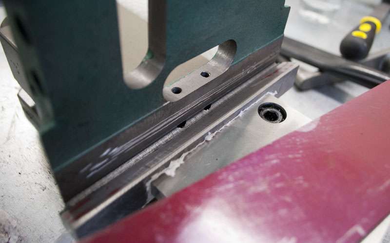
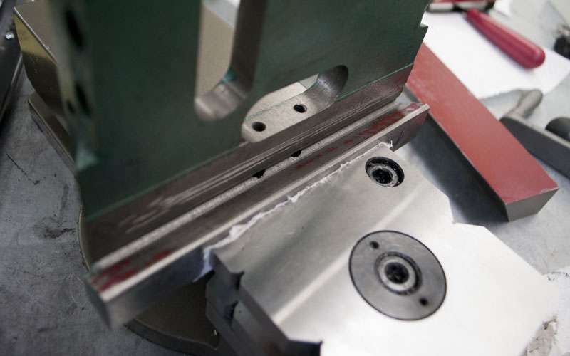
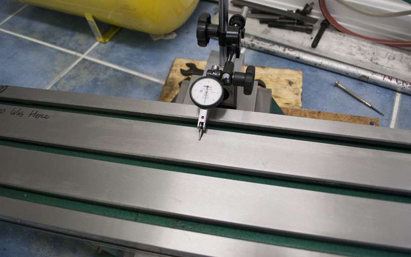
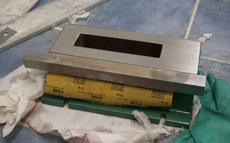
I mentioned earlier that one side of my table was tight. This suggests that the ways on the table are improperly ground. I decided that the most practical way to fix this is by lapping.
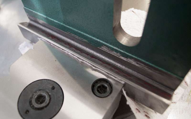
Surprisingly enough, the problem became pretty obvious:
You can see that there was a bump in the way that has been completely worn down, not even the machining marks remain.
I don't know how they managed to leave a bump like that on a surface grinder.
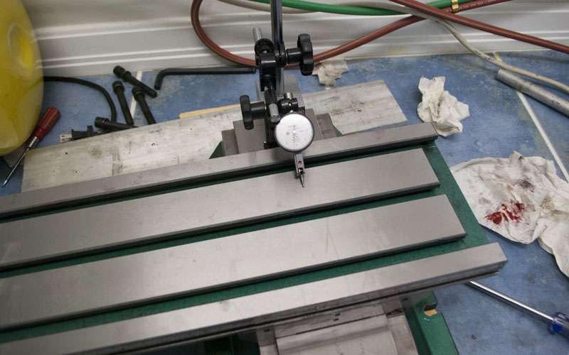
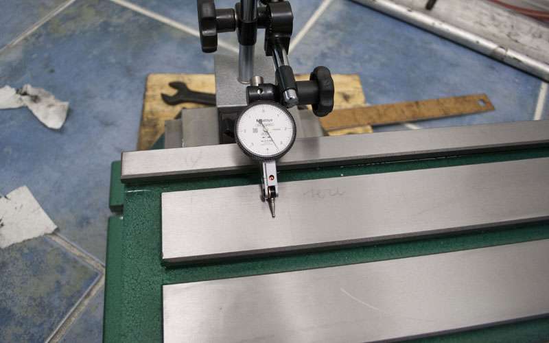
Time to test the results:
Zeroed on the center.
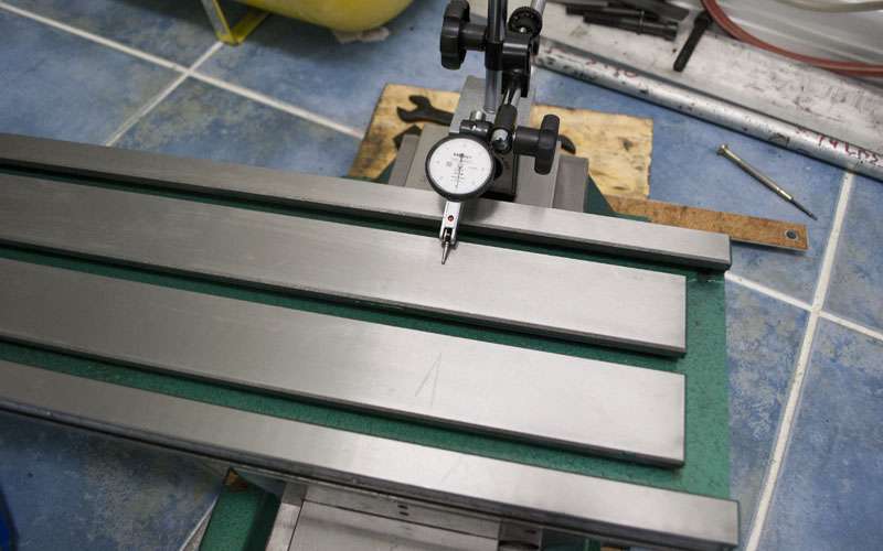
Still zero.
Two tenths.
Things start getting ugly here.
It makes sense in hindsight, I removed a bump from the ways and now that spot is low.
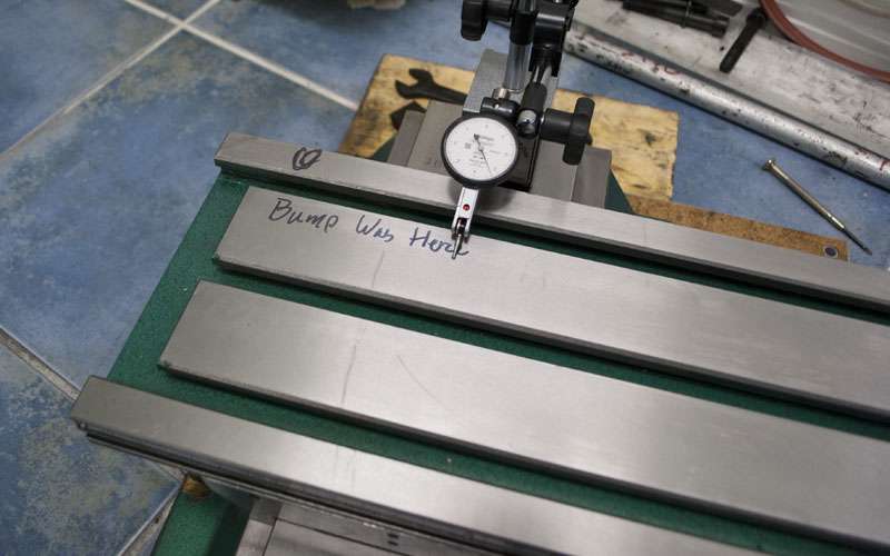
The trade wasn't actually all that bad since the right side of the table is more accurate but I decided to try fixing it anyway.
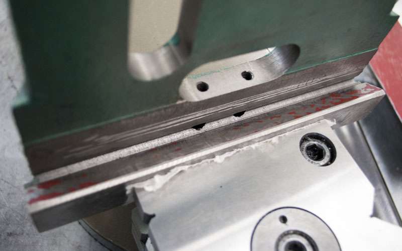
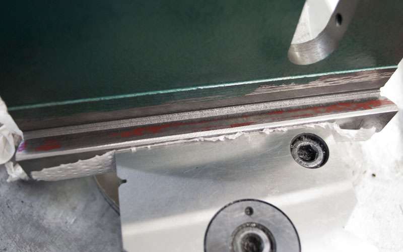
The plan sounds silly, but I figured if I apply downward pressure when lapping the high side and lift the saddle when I lap the low side I can sort of alter the geometry of the ways.
Lift on this side...
I was a bit worried about my surfaces becoming convex so I spotted the saddle. Luckily it does not seem to have negatively impacted the surfaces.
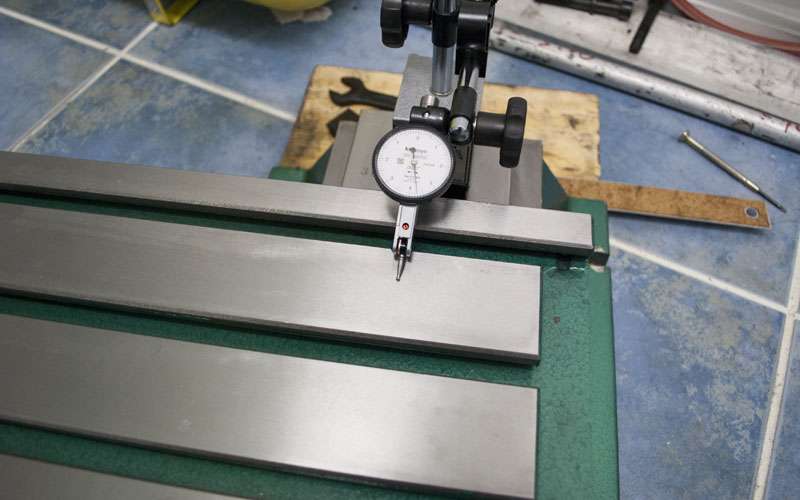
Finally one last check from right to left:
Zero.
One tenth.
Two tenths.
Four tenths.
So the lapping ended up working out fairly well. I could probably keep going but it feels like I've hit diminishing returns and I don't want to lap too much.
Obviously this process would only appeal to a very small number of people, but getting these kinds of numbers is going to cost either a lot of money or a lot of time. I am extremely pleased with the results:
- Way squareness 2 thou -> <0.2 thou
- Table Z error over entire X axis 3 thou -> 0.4 thou (0.2 for useful travel)
- Table Z error over entire Y axis 1 thou -> <0.2 thou
- Basic Flex Test 1 thou -> 0.1 thou
- Much easier to slide the travels.
I've managed to significantly increase the rigidity and accuracy of my g0704, and assuming that the glass scales work out it should be possible to get better than 0.0005" accuracy over most of the table.
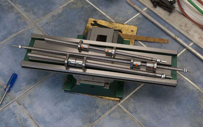
Next up is the ballscrews, I am going to try fitting double nuts into each axis as well as extending Y and Z travel:
-
07-16-2012, 12:43 PM #39
Registered
- Join Date
- Feb 2012
- Posts
- 296
Great results and pictures!
If you were to take a guess how many hours would you say you have put into the scraping/lapping and would you recommend it to a complete beginner?
I keep bouncing back and forth trying to decide whether or not I want to scrape my machine...I may skip it for the initial setup and see how good it can do and then if I am not happy I will take it back apart and start scraping.
Thanks!
-
07-16-2012, 05:47 PM #40
Registered
- Join Date
- Apr 2005
- Posts
- 419
I put about 60 hours of scraping to get to this point, and it is fairly tedious stuff. I would certainly scrape a machine again, but it is hard to say if I can recommend the process. It is extremely labor intensive and doing the job properly requires some reasonably expensive tools.
Lapping vs scraping has been a contentious topic in the past and I've always been on the scraping side of the fence (which is why I scraped this machine). But after trying both processes, I am more comfortable recommending lapping. It is easier, cheaper, and faster; and I was impressed by how well it worked when I gave it a go on the X axis.
Lapping certainly won't correct alignment errors, but I've discovered that because most of the error is caused by poor fits, you can still get 50-75% of the benefit with 10-20% of the work.
Both processes have their place, but from a return on effort perspective lapping definitely wins.
If you want to be as close to perfect as you can get, then scraping (or a surface grinder) is really the only option you have, but getting those last few tenths is going to take a lot of time or money.
For what it’s worth, I used the cheapest non-embedding compound I could find. Two grits of Triumph from MusicMedic.com: Triumph Lapping Compound costs ~15$ and works fine.

 Reply With Quote
Similar Threads
-
G0704
By kd4gij in forum Benchtop MachinesReplies: 8Last Post: 07-07-2016, 12:00 AM -
DRO for G0704
By UMR in forum Benchtop MachinesReplies: 4Last Post: 07-06-2016, 04:04 AM -
No Joy with my New G0704
By DogWood in forum Benchtop MachinesReplies: 5Last Post: 07-05-2016, 05:49 PM -
G0704... Yes Another One ;)
By ww_kayak in forum Benchtop MachinesReplies: 24Last Post: 05-27-2013, 03:47 PM -
G0704 or a X-3
By USN in forum Benchtop MachinesReplies: 8Last Post: 05-30-2011, 08:24 AM
