


A few more electronics queations before I order. I have done some searching and some reading but still have questions about supplying power to the C32 and ESS. I like the idea of optoisolated inputs and outputs and am trying to get a head count on 5v supplies. It looks to me that (1) 5v 3a will cover the main power if the C32 and ESS. Then I would need (1) 5v for inputs (limit switches) and (1) 5v for outputs (drivers) for a total of (3) 5v supplies. Is this correct and or necessary? With my lack of skill level on electronics I would rather buy a few extra supplies rather re-buying everything when I short something out.
Thanks
Thread: rob_b's G0704
Results 41 to 60 of 62
-
06-20-2012, 11:26 PM #41
 Registered


- Join Date
- Jun 2008
- Posts
- 36
-
06-21-2012, 01:45 AM #42
Gold Member
- Join Date
- Feb 2006
- Posts
- 7063
You need a single 5V supply for the BOB and all I/Os, and a second one just for the PC-side of the BOB, including the ESS. That one need not be very large as it will only power the optos, a small amount of logic on the BOB, and the ESS. I'd expect even 1A would be plenty.
Regards,
Ray L.
-
06-23-2012, 12:53 AM #43
Registered
- Join Date
- Jun 2008
- Posts
- 36
Thank you sir, but now my Paypal is crying worse than before.
-
06-23-2012, 03:43 AM #44
Registered
- Join Date
- Dec 2006
- Posts
- 839
Look around you probably have a wall wart laying around that will work. If all you can find is a higher volt one just build a little circuit board to regulate it down, it wouldnt cost more than a couple bucks to go to Radio Shack and egt the 5v regulator and a board to build it with. Lots of digrams around the net to build one from also.
JessGOD Bless, and prayers for all.
-
06-23-2012, 01:05 PM #45
Registered
- Join Date
- May 2004
- Posts
- 600
Hey Jess (Lucky13), could you please clear your PM box as it's full and I was trying to contact you re DMM AC Servos.
Sorry for posting this here guys but I couldn't think of another option.
Regards
Skippy
-
06-24-2012, 03:25 PM #46
Registered
- Join Date
- Jun 2008
- Posts
- 36
I deleted my bogus wiring diagram (end of page 1) as to not lead others down the wrong path I was taking...
Most all of the electronics and other hard parts are now in hand. So I started getting more serious about chipping away at the 3D model in Inventor however I still have a long ways to go. Right now I have all of the conversion parts drawn off the Hoss plans but am planning to change it up just to make it my own.


-
06-24-2012, 04:47 PM #47
Member
- Join Date
- Feb 2004
- Posts
- 1311
You need to add clutter to your table top, boxes in the corners and under the desk and swarf every where to make it look more realistic!
Seriously, nice job!
cheers,
MichaelReelsmith, Angling Historian, and Author of "The Reelsmith's Primer"
www.EclecticAngler.com | www.ReelLinesPress.com
-
06-24-2012, 07:42 PM #48
Erfahrener Benutzer
- Join Date
- Feb 2012
- Posts
- 234
I agree 100% Originally Posted by mhackney

will you be sharing the model?
-
06-24-2012, 09:45 PM #49
Registered
- Join Date
- Jun 2008
- Posts
- 36
Haha, thanks guys. Not sure about sharing the model. I intentionally simplified the parts by removing some features like tapers/fillets/chamfers that I felt were not important in the overall scheme of things. Also, the +/- tolerances of the machine as a whole are all over the place. I can guarantee that your machine has different bolt patterns and such than mine does. I'm guessing that is why there are so many parts with the machine number stamped on them.
Anyway here is an overview shot of my WIP "machining center" The bench is 2x4 construction on 16" CL with a 3/4" particleboard top that's covered by 12ga steel that wraps 3 sides, legs are 4x4's. I'm pretty tall so the bench is too.

7x Lathe with it's most used tooling

The only parts going back in the G0704
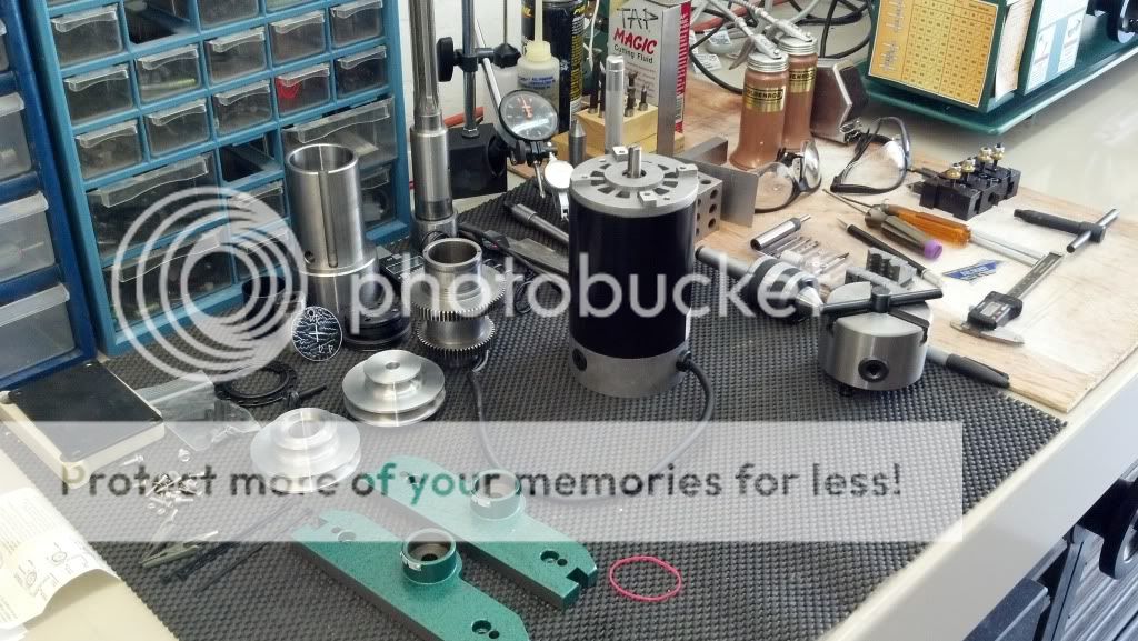
Current state of the G0704

-
06-29-2012, 08:41 PM #50
Registered
- Join Date
- Jun 2011
- Posts
- 0
Nice work and you won't go wrong with Hoss's plans as he'll stand over all his products and guide you if help is needed.......
Love the workshop and keep the pics flowing.....thanks for sharing Eoin
Eoin
-
07-21-2012, 09:58 PM #51
Registered
- Join Date
- Jun 2008
- Posts
- 36
Been chipping away at the control. Hope to have it all wrapped up by the time the weather cools down enough to revisit the garage and start working more on the mechanical. I did a temporary test run and got all axis working, the spindle is under mach control using the stock ESC and a game pad working as a pendant. My plan here is to get all control components mounted and wired to this board then mount it in a steel enclosure where I can then layout all of the I/O connections. Anyways, small update with a little progress.

-
08-25-2012, 09:05 PM #52
Registered
- Join Date
- Jun 2008
- Posts
- 36
Getting happier with the Y axis drive setup in the computer.
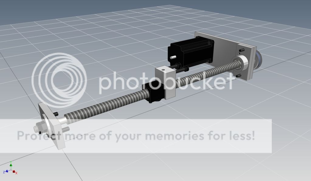
I like the idea of a front bearing.
26T XL pulley's

Thinking of boring a 1.5" hole in to back of the column to sink the bearings into to minimize the foot print.
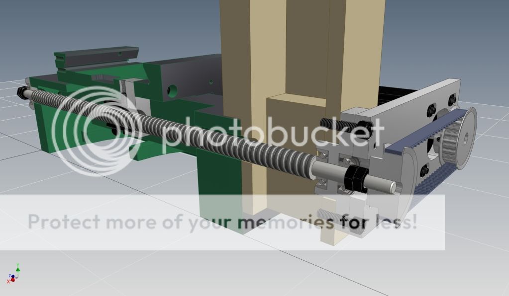
Probably stupid but I was thinking the slot could capture the stepper mount nut.
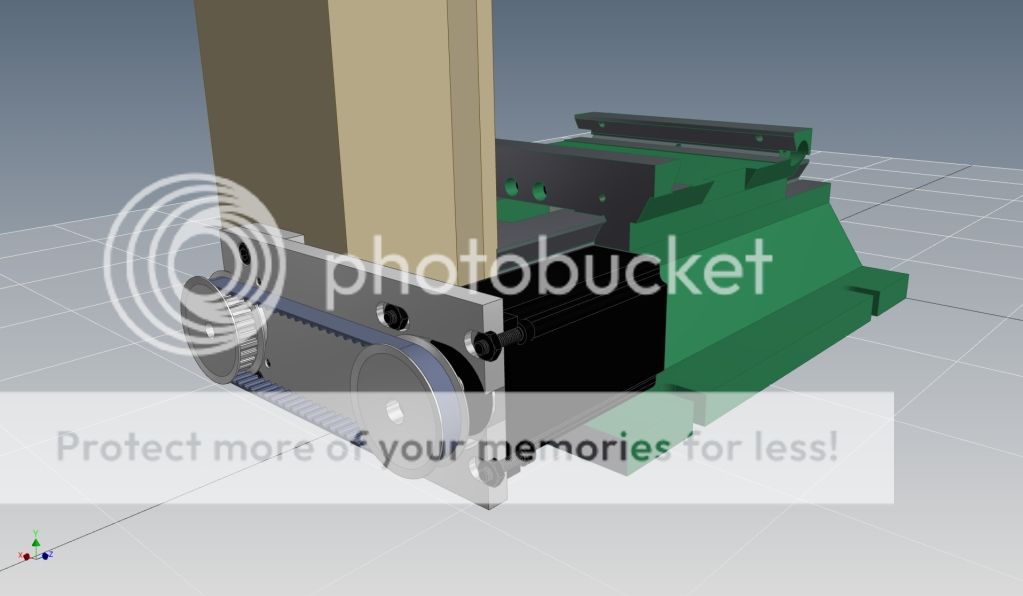
I know that I'm not breaking any new ground here but would love some feedback on this setup.
-
08-25-2012, 09:23 PM #53
Registered
- Join Date
- Jul 2012
- Posts
- 80
I would think that you wouldn't want nuts on the front of the Y-Axis ballscrew, since this end it just supposed to float. The AC bearings at the back take the load, and the front bearing just supports the screw radially. You need to allow for screw length changes with temperature, so you don't want the same support on both ends.
Other than that, it is looking really good.Michael Anton
http://manton.wikidot.com - http://laserlight.wikidot.com
-
08-25-2012, 11:06 PM #54
Registered
- Join Date
- Jun 2011
- Posts
- 0
There's no issue with the 1.5" hole as I myself drilled the exact same diameter but in mm's of 40mm http://www.cnczone.com/forums/1068714-post70.html, but you may have to redesign your A/C bearing allocation.....have a look at the pic to see the reinforcing around the Column Bolt holes in the Column casting....now I know mine is the BF20 version but I asume that the Grizzly is similar but you should clearly be able to view the casting as you have your cloumn and base disassembled Originally Posted by rob_b
Eoin
-
08-25-2012, 11:08 PM #55
Registered
- Join Date
- Jun 2011
- Posts
- 0
Sorry meant to add in my last post too but I pressed the Submit too soon......geez I love the 3D drawings and rendering....well done, nice work
Eoin
-
08-26-2012, 03:52 PM #56
Registered
- Join Date
- Jun 2008
- Posts
- 36
I had originally planned to configure the Y that way but forgot when the time came to model it.:tired: Thanks for the reminder. Isn't it standard to nut each end of the X screw though? Originally Posted by manton
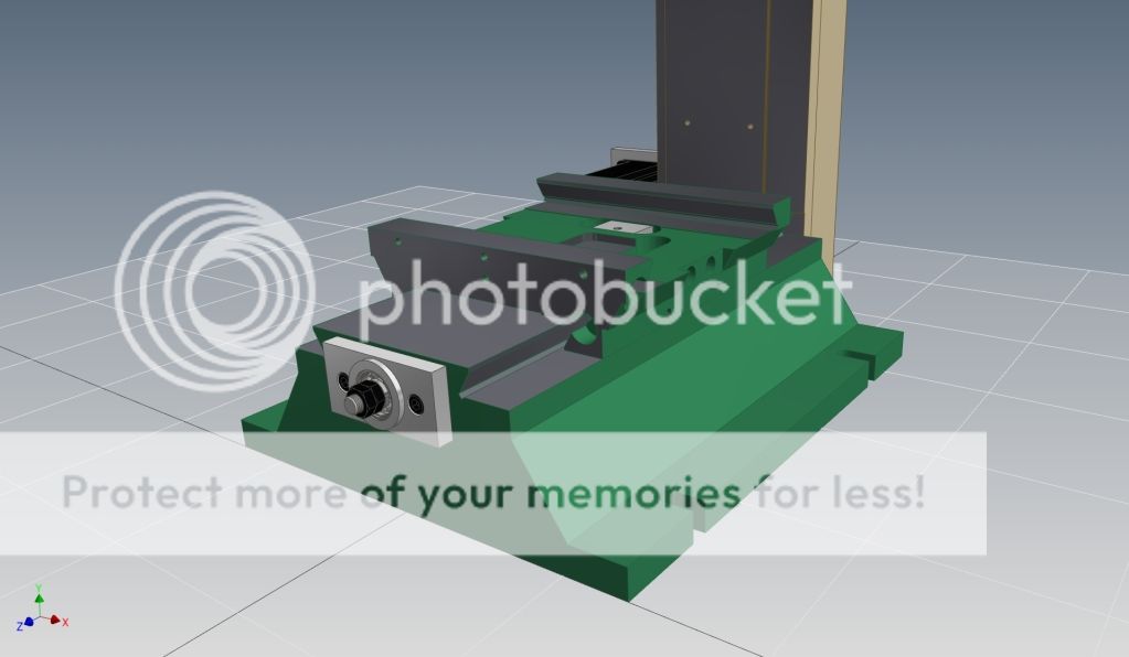
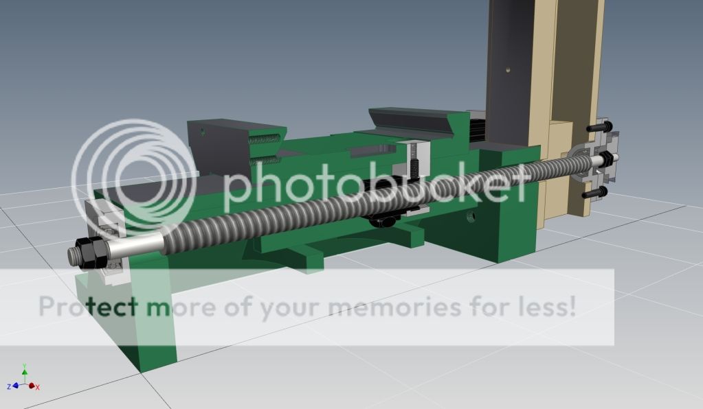
According to my measurements I'll only hit the reinforcement on one side and even then just barely. I have the OD of the bearing boss @ 1.400" to allow for a little alignment adjustment. Originally Posted by Mad Welder
Updated model...
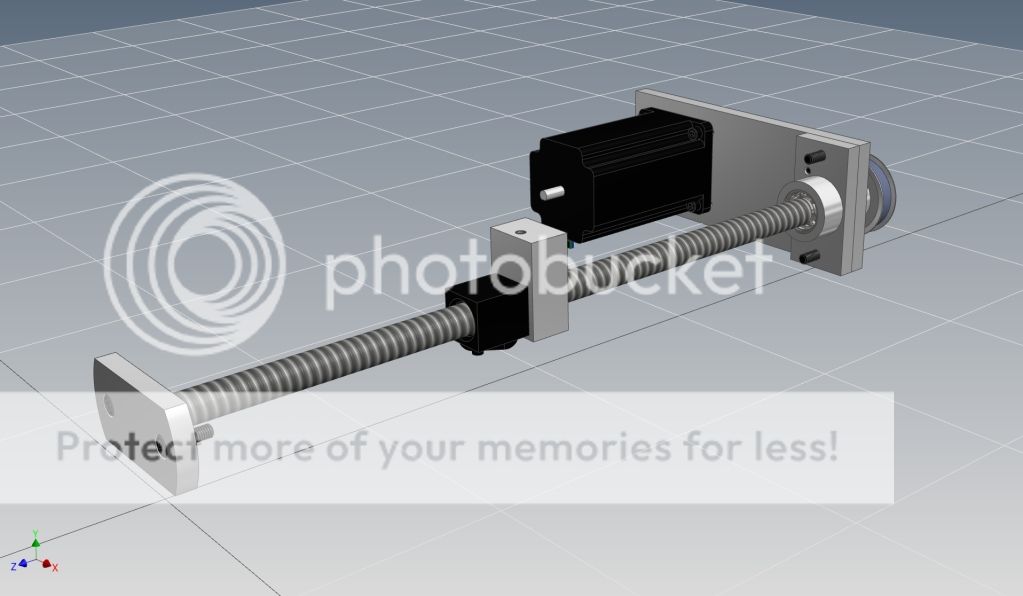
If nothing else it looks better. Eoin, I really like how you made your front bearing spacer out of round stock then milled the top flat so I'm stealing the idea...

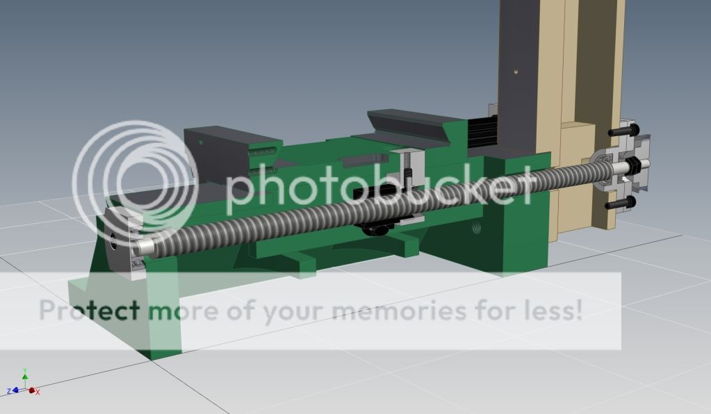
Here you can see better (in red) where the 1.500" hole will hit the wall.

Oh, forgot to mention the spring pins to keep the stepper plate and bearing mount aligned.

-
02-25-2013, 11:15 PM #57
Registered
- Join Date
- Jun 2008
- Posts
- 36
Been hacking away at the base conversion parts during break times and lunch for a while now. Didn't take many pictures along the way but was able to do some initial testing (minus spindle) this weekend. Not bad for my first rodeo
G-Code skills are in need of some work.
Feeds 25,50,100,200,250... YouTube
Converted a 6" rotary too... YouTube
-
02-26-2013, 12:03 AM #58
Registered
- Join Date
- Jul 2012
- Posts
- 80
I think the only reason that the X usually has nuts on both ends, is to hold the handles on, at least on a manual machine. The end without preload, usually has the nut just tight enough to hold the handle on, it still allows the screw to expand an contract. Of course on a CNC machine, this would be different, especially considering that on a manual machine, the screw likely doesn't change temperature much, as the feeds are different, and the machine is not pushed as hard, for as long. Originally Posted by rob_b
Michael Anton
http://manton.wikidot.com - http://laserlight.wikidot.com
-
02-26-2013, 01:30 AM #59
Registered
- Join Date
- Jan 2007
- Posts
- 243
Get a Mini-Mill. Perfect for RC after-market parts.
www.WebMachinist.Net
The Ultimate Online Source for Machinist Related Stuff!
-
02-26-2013, 02:36 AM #60
Registered
- Join Date
- Jun 2008
- Posts
- 36
Re: rob_b's G0704
Makes since on the dials.
A mini-mill would be really sweet but I think it will hurt much less if I learn and crash on this mill for starters.

 Reply With Quote
Similar Threads
-
G0704
By kd4gij in forum Benchtop MachinesReplies: 8Last Post: 07-07-2016, 12:00 AM -
DRO for G0704
By UMR in forum Benchtop MachinesReplies: 4Last Post: 07-06-2016, 04:04 AM -
No Joy with my New G0704
By DogWood in forum Benchtop MachinesReplies: 5Last Post: 07-05-2016, 05:49 PM -
G0704... Yes Another One ;)
By ww_kayak in forum Benchtop MachinesReplies: 24Last Post: 05-27-2013, 03:47 PM -
G0704 or a X-3
By USN in forum Benchtop MachinesReplies: 8Last Post: 05-30-2011, 08:24 AM
