


I recently completed converting my Taig mill to CNC. I'll document the process in this thread.
Todd F.
Results 1 to 20 of 60
-
04-10-2012, 12:46 PM #1
 Registered
- Join Date
- Feb 2012
- Posts
- 0
Completed Taig mill conversion to CNC
-
04-10-2012, 12:50 PM #2
Registered
- Join Date
- Feb 2012
- Posts
- 0
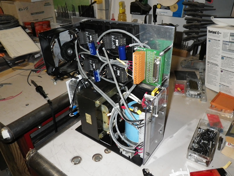
This is the four axis stepper motor driver I built to convert my Taig milling machine to CNC control. It uses two power supplies. To drive the steppers, I used an Elpac BFS 500-24 unregulated power supply. With no load, it supplies 36 VDC. At a full load of 20 amps, it drops to 24.6 VDC. To supply 5 VDC for limit switches and logic inputs, I broke open a wall wart power supply from a powered USB hub. The motor drivers are IB463 units from Intelligent Motion Systems. These take 12-40 VDC supply power and output 3.5 amps per phase to the stepper motors. These drives are tricky to interface because their opto-isolated inputs require current limiting resistors to prevent blowing out the optocouplers with 5 volt logic signals. To get the logic signals from the parallel cable to the motor drivers, I used a Weidmuller parallel port breakout board. 120 VAC power from a wall outlet is switched with a standard light switch, which also turns on a fan to keep the stepper drivers cool.
To control the driver, I'm using an older PC running LinuxCNC (EMC2). Getting that running was a multi-day project in and of itself. Linux still has a way to go to become an everyman's operating system. Without a lot of experience building computer systems from scratch, and the ability to do web searches on my normal desktop computer, I would have given up in disgust. In the end, I was able to use EMC2 to confirm that all the axes were functioning before disassembling the milling machine. The first time I got a stepper motor to move under control was a major thrill.
Todd F.


-
04-10-2012, 01:23 PM #3
Registered
- Join Date
- Feb 2012
- Posts
- 0
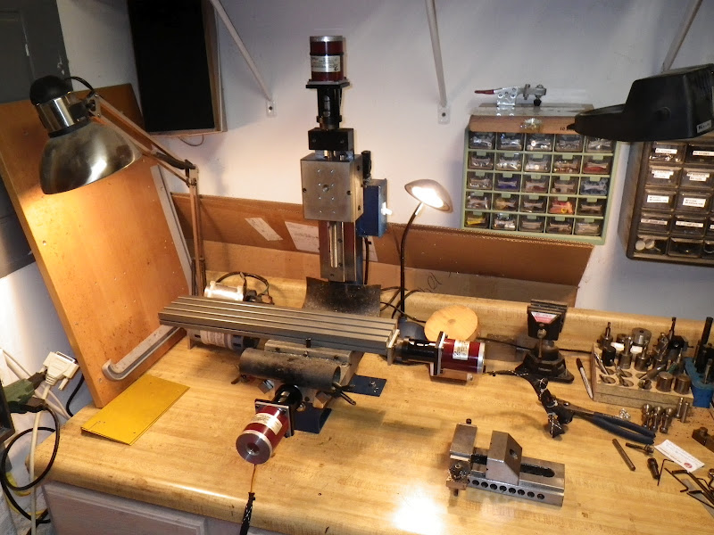
Here is the milling machine before I started disassembly.

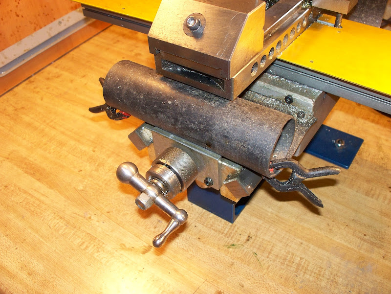
This is a closeup of the bed of the machine. For work holding I use a vise from Enco. The bed is protected by the aluminum covers. Also visible is my homemade boring jig.

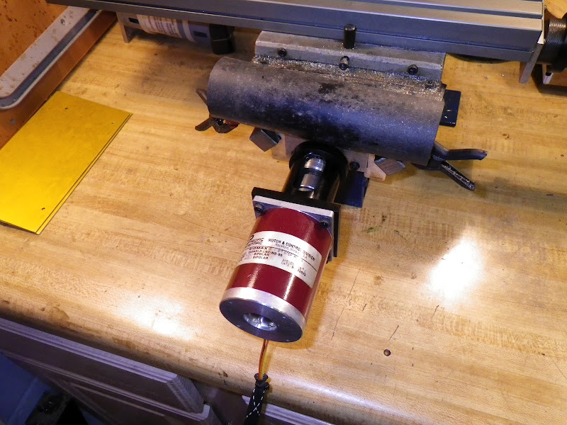
Closeup of the Z-axis handle and spindle motor.

Closeup of the Y-axis handle and way cover.
Todd F.
-
04-10-2012, 02:32 PM #4
Registered
- Join Date
- Feb 2012
- Posts
- 0
The next step in the conversion process was to disassemble the milling machine and replace the standard leadscrew nuts with anti-backlash nuts. I installed the nut fot the Y-axis and the Y-axis stepper first, followed by the X-axis and Z-axis. Here is the mill after the Y axis installation.

This is after the Z-axis was reinstalled, but before reassembling the spindle.
While reassembling, I took the opportunity to recheck the alignment of the Y axis column to the X-axis table. I also made sure the spindle dovetail was true. Surprisingly to me, nothing needed adjustment.
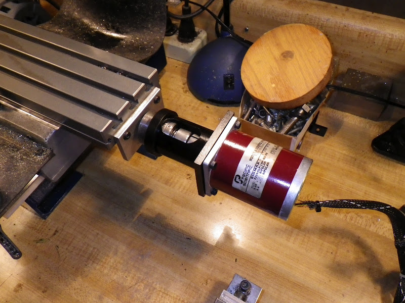
Here are the Y, X and Z axis stepper motors.

Last, I installed the control computer in the cabinet, under the workbench, put the stepper driver on a shelf above the mill, and wired the steppers to the driver electronics.

Eventually I'll add homing limit switches and buttons for enable and e-stop, but for now, I was eager to see what the mill could do.
Todd F.
-
04-10-2012, 03:26 PM #5
Registered
- Join Date
- Feb 2012
- Posts
- 0
For my first test I used the text that loads up as a default when EMC2 starts up. I used a 1/8" endmill to cut the text into a piece of scrap pine I had laying around.
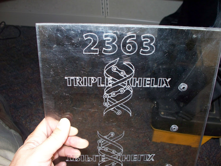
Next, I decided to engrave the logo of the FIRST robotics team for which I am a mentor. That led to a hunt around the web for free software which would generate gcode. I attempted to use a free utility to convert the logo from pdf to dxf and then generate the gcode using HeeksCNC. This failed because of how the utility converted the logo. I eventually imported the pdf directly into Inkscape and used the gcodetools add-on to generate the gcode. Once I got through the learning curve of using the software, this worked great. I was able to do experimentation, engraving on the front side of 1/4" lexan, 1/8" lexan and 1/6" anodized aluminum. My best results were from reversing the image and engraving on the back side of 1/4" lexan.
Engraving in scrap piece of lexan.
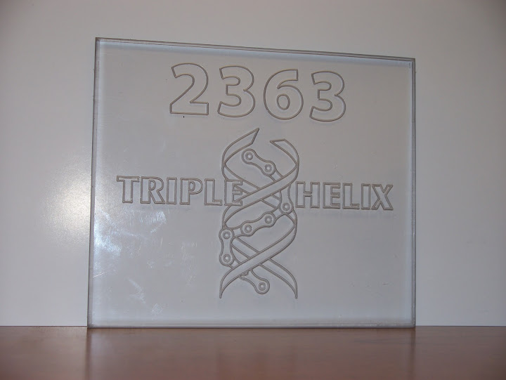
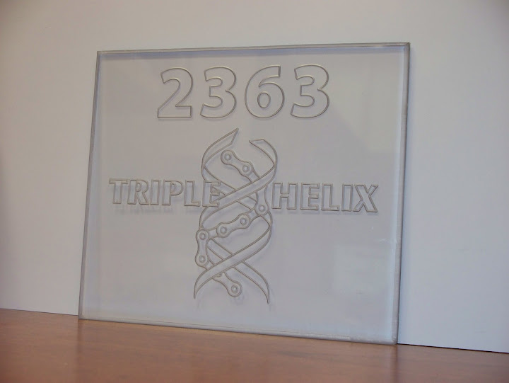
Engraving on nice piece of lexan.
Video of engraving on 1/8" lexan and 1/16" anodized aluminum.
Todd F.
-
04-11-2012, 01:15 PM #6
Registered
- Join Date
- Feb 2012
- Posts
- 0
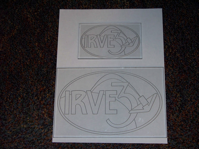
Last night I did a couple engravings of the IRVE3 project logo. This is the project I'm assigned to at work.
Todd F.
-
04-11-2012, 02:47 PM #7
Gold Member

- Join Date
- Nov 2009
- Posts
- 4415
Fun, huh? Nice work
-
04-12-2012, 12:21 AM #8
Gold Member
- Join Date
- Apr 2005
- Posts
- 438
Thanks for posting, I have been thinking of getting a taig mill and cncing it. On the anti backlash nuts, were they just a drop in replacement or did you have to modify anything?
tks
-
04-12-2012, 02:40 PM #9
Registered
- Join Date
- Feb 2007
- Posts
- 456
The anti-backlash nuts are a direct replacement. In fact for the last six months or so I believe Taig has been supplying the adjustable nuts on the manual mills as well. The older, non-adjustable nuts, are no longer availavble as spares either.
Jeff Birt
-
04-18-2012, 10:34 AM #10
Banned
- Join Date
- Jul 2009
- Posts
- 205
the adjustable split nuts have been standard for at more than 5 years, at the very least, on all the cnc-ready mills.
op had a manual mill which is why he had no adjustable nuts.
-
04-19-2012, 12:48 PM #11
Registered
- Join Date
- Feb 2012
- Posts
- 0
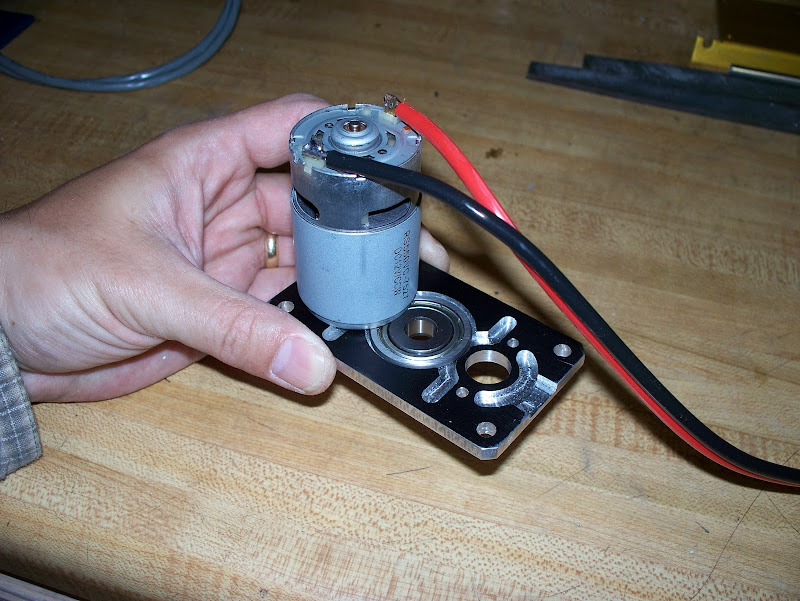
I made my first 2.5 axis machined part yesterday.

This is a plate which mounts two motors with pinions to drive a single shaft running in a central bearing. It is a part our FIRST robotics team had made for us by a team sponsor. It was this part which really provided me the motivation to do my CNC conversion. I want the team to be able to design and make simple, small parts like this ourselves rather than relying on sponsor support.
I’m taking baby steps with the capabilities of my mill. This part required multiple tool changes, resetting the Z height between each one. I took my single gcode program and split it into a bunch of files so I could change tools and touch-off Z between each one. Next, I’m going to try keeping the program intact and using a user developed routine to jog and set Z at the manual tool changes. The production way of handling this is to have the different tool Z heights calibrated with respect to a reference tool, with each tool held in a swappable tool holder. But, I don’t know how to make that work when swapping drill bits in a drill chuck.
Pics here:
https://picasaweb.google.com/1099928...eat=directlink
One corner looks bad because I was using a piece of scrap that had a randomly placed existing hole in it. I tried to cheat to one side of the stock to miss the hole, but didn’t quite get far enough. On the first one, I didn’t want to take a chance of hitting a clamp with a tool.
Todd F.
-
04-20-2012, 08:38 PM #12
Registered
- Join Date
- Feb 2012
- Posts
- 0
I got the manual tool change with Z touch-off working. It took a while to figure out how to do this in LinuxCNC. After tons of looking, the best resource for making this work is this link.
The instructions for making this happen are unclear, and scattered across many different wikis and forum threads. Here are the steps I had to take to make it work. Hopefully these instructions will help others who are Linux novices like me.
These instructions assume you have LinuxCNC set up and running on a computer with umbutu linux.
- Download this file. Name it "hal_manualtoolchange", with no extension.
- I'm using umbutu linux, which makes changing system files hard. Open a terminal window and type "gksudo nautilus". This will open a graphical file manager with root privileges. You must make changes to the system from within this window.
- Find the existing file /usr/bin/hal_manualtoolchange and rename it to hal_manualtoolchange_backup. Copy the file you downloaded, above, to the /usr/bin directory.
- Go to the directory containing the LinuxCNC setup files for your mill. Edit the file "tool.tbl". To do this, right click and select "open with other" and choose "gedit". Gedit must be launched from within the file manager window possessing root privileges. The tool table file will already have some sample tools. Replace these tools with ones of your own, and set the offsets all to zero.
- Edit the file "<yourmill>.ini". Find the section called [EMCIO] and add the line "TOOL_CHANGE_POSITION = 0 0 2", replacing the 0 0 2 with the absolute X, Y and Z coordinates you want the mill to move to for tool changing. On my mill, my work envelope is 12"x5.5"x4.5", so I chose my tool change position to be "8 2 -.25"
- Run LinuxCNC. Home your machine. Load your gcode program. Install your first tool. Touch off the X and Y axes. Run the gcode. Almost immediately the mill should go to the tool change position and prompt you to install your first tool. It should already be installed. Switch active windows from the dialog box to LinuxCNC. Use LinuxCNC to jog the mill and touch off to Z axis. Switch windows back to the dialog box and hit OK. The program will resume. Follow the same procedure for the rest of the tools and operations in your program.
This allows the use of multiple tools without needing to break your gcode program apart into multiple files.
Todd F.
-
04-21-2012, 12:05 AM #13
Gold Member
- Join Date
- Apr 2005
- Posts
- 438
I'm probably missing something but can you explain the bit changes you have to do on that part.
From what I can tell by the picture I would do it with a .125 or .250 end mill depending on the smallest hole in the part.
Like I say I am most likely missing something, only do this as a hobby and sometimes over look the obvious
-
04-21-2012, 11:42 PM #14
Registered
- Join Date
- Feb 2012
- Posts
- 0
Here is a pdf drawing of the part.
Here are the general steps I use:
- Use center drill to locate all 11 holes.
- Use #7 drill on 4 corner holes and three center holes.
- Use small drill on four motor mount holes.
- Use .250" end mill to open up motor boss holes and center bearing hole.
- Use .188" end mill for air flow ventilation channels.
- Use the .250" end mill to cut out the profile.
I could have used the .188" end mill for some of the operations and saved a couple tool changes, but it is important that the motor boss and bearing pocket holes are exactly on size. The .250" diameter tool gives less tool deflection and a better surface finish than the .188" tool, so I wanted to use the bigger tool for the critical sized pockets. And cutting the perimeter is a lot of hogging of material, so I wanted to use the bigger sized tool for that, too.
I ran this part in aluminum the other night and the speed was just a bit fast. The part ended up slipping in the clamps during the cutting of the airflow channels. No big deal, as those aren't dimensionally critical. I'm going to reclamp the part tonight and finish cutting it with slower cut speeds.
Just for the fun of it, here is a picture of this part in use on our robot at the FIRST robotics North Carolina regional competition.
Todd F.
-
04-23-2012, 04:42 AM #15
Registered
- Join Date
- Feb 2012
- Posts
- 0
The motor plate turned out great, with most dimensions within +/- .001 of programmed dimensions. I had to slow the speeds to less than half the lexan material. Even then, plunging with a two fluted endmill was too fast and caused significant vibration. HeeksCNC allows rampdown for pockets, but only lets you plunge for profiling.
Todd F.

-
04-24-2012, 04:43 AM #16
Registered
- Join Date
- Jul 2006
- Posts
- 10
Part looks very nice, and the mill conversion looks good; I'll admit I'm too lazy and got a CNC ready model from the get-go

If you dont mind me asking, what feed rates were you using for the Alminium? also what depth of cut are you going with? Also, are you using any coolant, I find WD40 works ok when you don't have anything else sitting around.
-
04-24-2012, 07:19 AM #17
Registered
- Join Date
- Sep 2007
- Posts
- 200
the build looks great, good to see you have started making parts.
one thing i would encourage you to do is re-mount those electronics in an old stripped out pc case. the thing being that electro-magnetic radiation has the tendency to scramble the signal wires. and look into sheilded stepper motor wire. it really makes a difference.
-
04-24-2012, 10:15 PM #18
Registered
- Join Date
- Feb 2012
- Posts
- 0
The feed rates I started with: Originally Posted by Hirearch

10 ipm horz, 10 ipm vert
what I ended with:
5 ipm horz, 5 ipm vert
with .050 depth of cut
I'm going to keep the same horz speed and go to .025 depth of cut, and go to 2 ipm vertical and see if that seems better.
For this first part, I used WD-40 for coolant, as my bottle of Cool Tool was nearly empty. I found a fresh bottle when cleaning the garage the other day, so I'll probably go back to using that.
Todd F.
-
04-24-2012, 10:26 PM #19
Registered
- Join Date
- Feb 2012
- Posts
- 0
All my signal wires are shielded twisted pairs. My stepper wires are also shielded twisted pairs. The surplus cable I stumbled upon was actually 3 conductors twisted with a shield. For the steppers, I ran two cables to each motor. One cable carries the A winding, and the other carries the B winding. The extra conductor in the cable is left floating. The shield is grounded at the controller end to the stepper driver power supply. Originally Posted by draughted
The manual for my stepper drivers is very good on the subject of recommended wiring and shielding practices. I read it about 5 times to make sure I was doing things right. I've attached it in case it is useful for anyone else.
Todd F.
-
05-07-2012, 01:50 AM #20
Registered
- Join Date
- Feb 2012
- Posts
- 0
This weekend I added home switches to the mill.
X axis home switch:

Y axis home switch:
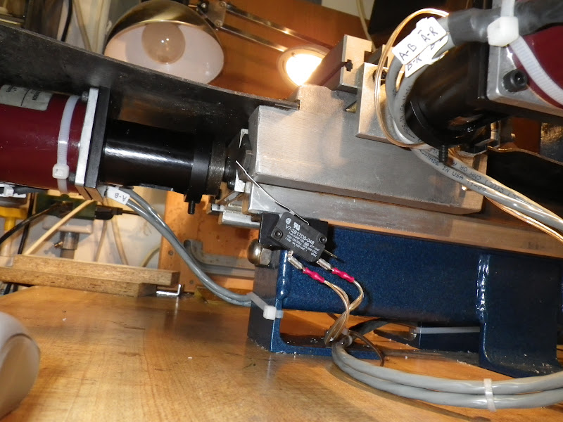
Z axis home switch:

I learned some lessons along the way about how LinuxCNC handles home switches. I wired all mine to the same pin, planning ahead for limit switches later. If you do this, it is necessary to set up each home switch in turn, adjusting the switch position and home position such that the home position backs off the switch. If you do not back off the switch, and it remains closed after homing that axis, when the software moves to the next axis, that axis will run the wrong way, as the software tries to open the switch. This leads to frantic punching of the estop button and much head scratching. Eventually light dawned, and everything was smooth sailing from then on.
Todd F.

 Reply With Quote
Similar Threads
-
Completed NMTB30 conversion on IH mill
By Runner4404spd in forum Charter Oak Automation Support ForumReplies: 27Last Post: 03-14-2010, 04:24 AM -
Small CNC Mill: X2 conversion, Taig, KX1, or something else?
By awetmore in forum Benchtop MachinesReplies: 0Last Post: 02-01-2010, 10:16 PM -
Taig mill conversion completed
By oisyaot in forum Taig Mills / LathesReplies: 10Last Post: 12-10-2008, 10:53 PM -
Completed my X2 mill conversion :)
By LongRat in forum Benchtop MachinesReplies: 10Last Post: 07-30-2006, 02:26 AM
