


Hello again...
i've received my electronics package,
set up an old PC and installed Mach3
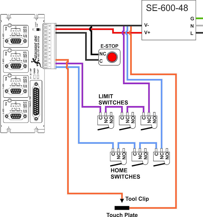
and been reading this forum for hours to figure out/plan the wiring for G540 and pretty much came up with this.
questions:
1) by wiring Home and Limit in series as illustrated, the machine will travel for longer period of time?
2) Mach3 setup, i guess i'll have to watch their vid again... but still not sure how to set up in M3.
3) what gauge wires to use for the switches and probes? 18ga?
4) does everything look ok?
quite anxious to get things moving...
your suggestions/comments/critiques much appreciated.
thanks in advance.
Al
Thread: G540 wiring questions
Results 1 to 20 of 67
-
03-18-2012, 07:54 AM #1
 Registered
- Join Date
- Apr 2009
- Posts
- 266
G540 wiring questions
-
03-18-2012, 11:48 AM #2
Registered
- Join Date
- Feb 2012
- Posts
- 0
i think you misunderstood the limit/home switch connection diagram.
you don't need to seperate per type of switch like 'home' and 'limit' but you need to seperate per axes 'x' , 'y' and 'z' (and on my router the tooltip = my z-limit).
personaly i don't know if you can use 2 types of switches for the Z-home?
i always thought you could only use one, either a switch or a tooltip 'touch' plate as switch.
ps: with this i could use some help to because on my own router the home switches make the router go to the 'home 'position but my tooltip just acts as a reset button, i still need to fix that myself too ....
isn't this more correct for you then?

-
03-18-2012, 12:21 PM #3
Registered

- Join Date
- Dec 2007
- Posts
- 362
Check out the wiring diagram from Homann Designs. It contains everything you need.
Regards
Geoff
-
03-18-2012, 02:04 PM #4
Registered
- Join Date
- Dec 2010
- Posts
- 634
Actually, both methods will work. There's not really too much benefit in having limit switches separate from your homing switches unless you're not homing to a limit. So, you can wire all 6 switches in series to a single pin for homing and limiting. Originally Posted by effimos

Once you have a homing arrangement though, you'll find that soft limits in Mach 3 work pretty well.
Finally, your tool touch thing might not work if your tool has proper grounding. Better to wire the touch plate to an input and have the tool grounded. If your router is insulated such that the bit isn't grounded, your arrangement will work.-Andy B.
http://www.birkonium.com CNC for Luthiers and Industry http://banduramaker.blogspot.com
-
03-18-2012, 02:09 PM #5
Registered
- Join Date
- Dec 2010
- Posts
- 634
When wired in series to a single input, Mach homes one axis at a time. I think I've read that if you have them on separate pins, it's possible to home everything simultaneously which would be faster. Originally Posted by kinghong1970
-Andy B.
http://www.birkonium.com CNC for Luthiers and Industry http://banduramaker.blogspot.com
-
03-18-2012, 02:11 PM #6
Registered
- Join Date
- Mar 2011
- Posts
- 584
for setting up mach 3 install the XML file from this link Support
You'll still need to set up some stuff but its much quicker this way.
-
03-18-2012, 04:26 PM #7
Registered
- Join Date
- Apr 2009
- Posts
- 266
nice photochop job! Originally Posted by effimos
i've read that both ways works... just trying to find out if there's a "better" way
i've checked his wiring diagram... took a while interpreting his image at 3:00am... lol... but finally, i understand it. Originally Posted by tumutbound
but it does seem that there's not much difference except that he uses a DE-9 connector to connect... which makes sense and must implement soon as i graduate from "newbie" status.
what i don't get is, why does he have 8 limit switches in addition to 4 home switches?
noted, thanks! Originally Posted by BanduraMaker
aaah, next lesson... but i recall Mach3 vids covered this... Originally Posted by BanduraMaker
so if this does not work, then ground it to the PSU ground (green)? Originally Posted by BanduraMaker
so if i wire it as effimos's image, will this allow for mach3 to move all 3 axis at same time? Originally Posted by BanduraMaker
and can i just use some Cat5e cables i have lying around for the home/limit/estop switches?
-
03-18-2012, 04:27 PM #8
Registered
- Join Date
- Apr 2009
- Posts
- 266
thank you... i did get the XML for the G540 from the gecko website... same? Originally Posted by vtx1029
-
03-18-2012, 04:38 PM #9
Registered
- Join Date
- Dec 2010
- Posts
- 634
Wire the touch plate into an input on the gecko and your "tool clip" to ground. Originally Posted by kinghong1970
I believe so but I've never actually tried it. I have my switches wired into one input.so if i wire it as effimos's image, will this allow for mach3 to move all 3 axis at same time?
It will work but I have no idea how Cat5e will handle noise. Try it, if you get limit trips when turning stuff on and off, switch to something shielded.and can i just use some Cat5e cables i have lying around for the home/limit/estop switches?-Andy B.
http://www.birkonium.com CNC for Luthiers and Industry http://banduramaker.blogspot.com
-
03-18-2012, 04:40 PM #10
Registered
- Join Date
- Apr 2009
- Posts
- 266
thank you Andy for your replies.
as for cable, what do you recommend?
-
03-18-2012, 04:41 PM #11
Registered
- Join Date
- Mar 2011
- Posts
- 584
Yes that is the one.
I could be wrong but i think Mach 3 will only home one axis at a time so there is no need to have separate inputs really. Direction doesn't matter either.
-
03-18-2012, 04:49 PM #12
Registered
- Join Date
- Dec 2010
- Posts
- 634
Probably some sort of coax cable with signal and shield/ground would be best. I just used something I had laying around and it works ok but I do sometimes get limit trips when I turn on my dust collector or vacuum pump. Haven't had any problems when actually running a job though. It hasn't been annoying enough to get me to actually do something about it Originally Posted by kinghong1970
 -Andy B.
http://www.birkonium.com CNC for Luthiers and Industry http://banduramaker.blogspot.com
-
03-18-2012, 04:59 PM #13
Gold Member

- Join Date
- Nov 2009
- Posts
- 4415
If using different pins for each axis on the homing switches (to allow simultaneous axis homing) requires a few changes. You will need to modify the VB script to command the 3 axis homing as the default is only single axis (not difficult necessarily it just wont happen automatically because you used 3 pins etc). If you happen to be running another machine from the same computer and that machine shares switches, it wont work. IIRC, Something about Mach only having access to 1 homing script per pc. I run many different profiles on a few different machine types (lathes, mills and soon a 3D printer) and had a few issues when trying multi axis homing. I could have one way or the other but each profile could not have its own homing script. In reality each machine really needs its own PC and Mach install.
-
03-18-2012, 05:32 PM #14
Community Moderator
- Join Date
- Mar 2003
- Posts
- 35538
You can home as many axis together as you want, if they are on separate pins.
Also be aware that if you have a slaved axis, you'll want a separate home switch so that homing will auto-square the gantry.
On my machine, I have the A axis slaved to the X axis, each on their own pins. The Y and Z share a pin. So I home the Z first, then the Y and X (+ the slaved A) all at the same time.
I don't use any limit switches, but the Z home switch is set up as a limit in Mach3.
You may not want your home switch at the end of the machines travel. Some people like to home in the center of travel. This allows you to have some room to move beyond where the home switch is.what i don't get is, why does he have 8 limit switches in addition to 4 home switches?
Also, a Z- limit switch can cause issues. If you use different length bits, you have to choose whether to allow long bits to cut through your table, or prevent short bits from reaching the workpiece. Realistically the only thing you can prevent is the collet hitting the table, or the Z axis sliding off the bottom of the rails.
Gerry
UCCNC 2017 Screenset
http://www.thecncwoodworker.com/2017.html
Mach3 2010 Screenset
http://www.thecncwoodworker.com/2010.html
JointCAM - CNC Dovetails & Box Joints
http://www.g-forcecnc.com/jointcam.html
(Note: The opinions expressed in this post are my own and are not necessarily those of CNCzone and its management)
-
03-18-2012, 07:54 PM #15
Registered
- Join Date
- Apr 2009
- Posts
- 266
noted, thanks! Originally Posted by ger21
aaah... then does the A also need a limit switch as well? Originally Posted by ger21
and squaring the gantry, wouldn't it also depend on the square positioning of the home switches for X and A?
aaah... Originally Posted by ger21
can't you also somewhat control this issue by position of the routermount and limit switches on the Z riser in comparison to the gantry? Originally Posted by ger21
-
03-18-2012, 08:30 PM #16
Community Moderator
- Join Date
- Mar 2003
- Posts
- 35538
No, it'll stop when you hit the X limit switch.aaah... then does the A also need a limit switch as well?
Yes, ideally the switch position should be adjustable.and squaring the gantry, wouldn't it also depend on the square positioning of the home switches for X and A?
I guess it depends on what you want the switch to prevent from happening?can't you also somewhat control this issue by position of the routermount and limit switches on the Z riser in comparison to the gantry?
You may fine that once you have your machine up and running, you may have a different idea of how to set up home and limit switches, based on the way you want the machine setup and how you work with it.Gerry
UCCNC 2017 Screenset
http://www.thecncwoodworker.com/2017.html
Mach3 2010 Screenset
http://www.thecncwoodworker.com/2010.html
JointCAM - CNC Dovetails & Box Joints
http://www.g-forcecnc.com/jointcam.html
(Note: The opinions expressed in this post are my own and are not necessarily those of CNCzone and its management)
-
03-18-2012, 08:34 PM #17
Registered
- Join Date
- Apr 2009
- Posts
- 266
thanks!
just picked up some 22AWG shielded wires from Lowes... i guess i'll see if i can get my motors turning tonight.
-
03-18-2012, 08:45 PM #18
Registered
- Join Date
- Apr 2009
- Posts
- 266
hmm...
the PSU unit turns on, output works, but cooling fan does not turn.
and a silent clicking... every 10 secs or so...
RMA?
-
03-18-2012, 09:24 PM #19
Community Moderator
- Join Date
- Mar 2003
- Posts
- 35538
Is it connected to anything?
Gerry
UCCNC 2017 Screenset
http://www.thecncwoodworker.com/2017.html
Mach3 2010 Screenset
http://www.thecncwoodworker.com/2010.html
JointCAM - CNC Dovetails & Box Joints
http://www.g-forcecnc.com/jointcam.html
(Note: The opinions expressed in this post are my own and are not necessarily those of CNCzone and its management)
-
03-18-2012, 09:43 PM #20
Registered
- Join Date
- Apr 2009
- Posts
- 266
oh, nvm Gerry, i'm a retard...
the mounting screw was a bit too long and it pushed against the fan housing.
i guess i'll resort to 3 hole mounting... till i get a smaller screw.

 Reply With Quote
Similar Threads
-
Another sPID, G540, and Mach wiring question for the wiring challenged..
By adam_m in forum DIY CNC Router Table MachinesReplies: 17Last Post: 01-02-2014, 01:29 AM -
Wiring Gecko G540 to PSU
By rnm85 in forum DIY CNC Router Table MachinesReplies: 12Last Post: 01-08-2012, 02:48 AM -
g540 complete wiring
By bel630 in forum Gecko DrivesReplies: 15Last Post: 08-31-2011, 12:01 PM -
X2 G540 Wiring Question
By Steoh in forum Benchtop MachinesReplies: 6Last Post: 03-02-2011, 01:53 AM -
G540 Wiring
By clamps in forum Gecko DrivesReplies: 3Last Post: 07-16-2009, 05:41 PM
