


It was a 3/8" carbide end mill running 1670 rpmOriginally Posted by aaron2496

I just put in the new abec 7 bearings and it runs a bit faster now...
Results 41 to 60 of 100
-
09-02-2012, 04:18 AM #41
 Registered
- Join Date
- Mar 2010
- Posts
- 156
-
09-04-2012, 03:41 PM #42
Registered
- Join Date
- Mar 2010
- Posts
- 156
Update:
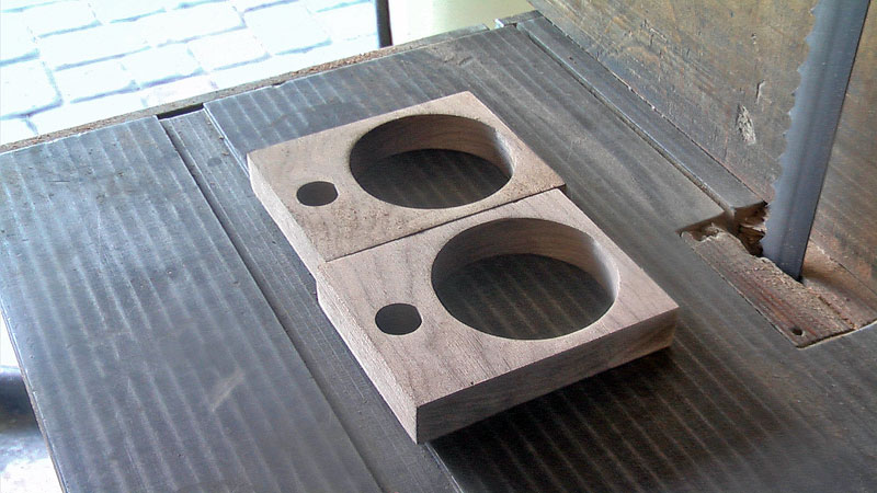
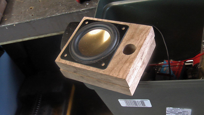
Well, I made my first actual parts: 2 face pieces for a set of speaker cabinets that will form the front of the speakers. I cut out wood because I needed to build some cabinets for some time + I figured I would be less likely to break another carbide bit on wood. Pretty simple but both cad and cnc are new to me and learning to draw in cad/cam, set stock size and machining origin is what these simple parts represent. I will use cnc to cut out the other sides and to round the cabinets + cut wiring terminal holes. The parts came out identical and the software even cut holding tabs for the outside rectangle to hold the part from rotating while being cut out. FYI, everything was done in cambam.
Video:
Finished parts:
-
09-04-2012, 06:13 PM #43
Registered
- Join Date
- Jun 2011
- Posts
- 0
Just came across your thread now gt40 and love the build thanks for sharing, and as was mentioned twice before geez I wish there was an Aluminium vendor with your prices flippin heck I'm being flat out robbed compared to your prices.....
Great videos too
and doorknob if you don't me asking....what's your build thread link?Eoin
-
09-04-2012, 10:52 PM #44
Gold Member
- Join Date
- Jan 2010
- Posts
- 2141
Had to smile when I saw that. Originally Posted by Mad Welder
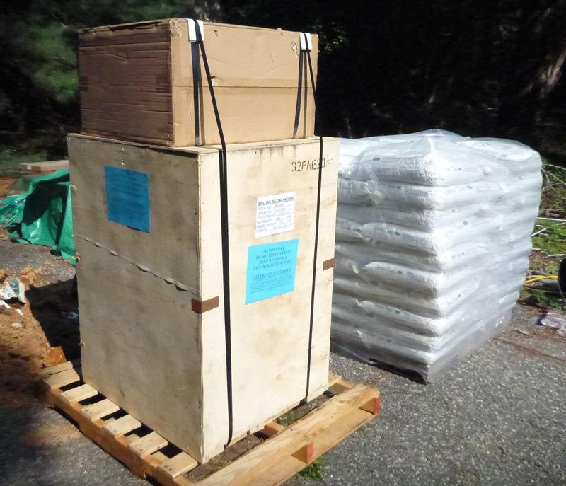
My PM45M was delivered just over a week ago.
It is still in the crate - have to empty out half of the garage before I can move it in there.
My first order of business will be to slap some cheap DRO scales on it and use it manually to mill some parts for doing a standard X2 mini-mill conversion.
I also plan to do other manual milling tasks before I get to the point where I'm ready to convert it to CNC.
So I'll get there eventually, but not for a while...
(see the attached photo of the PM45M stacked next to a pallet of pellet stove fuel)
Don't want to hijack this thread, though...
-
09-04-2012, 10:57 PM #45
Registered
- Join Date
- Mar 2010
- Posts
- 156
 Your pic brought a smile to my face. I remember the day my mill arrived. Congrats... Originally Posted by doorknob
-
09-04-2012, 11:03 PM #46
Gold Member
- Join Date
- Jan 2010
- Posts
- 2141
It's a big puppy, isn't it...

-
09-05-2012, 12:02 AM #47
Registered
- Join Date
- Jun 2011
- Posts
- 0

Aaaaahh but for now I can only dream of getting a big puppy like you both have there
 Eoin
Eoin
-
09-06-2012, 03:24 PM #48
Registered
- Join Date
- Mar 2010
- Posts
- 156
thanks for your kind words. I have learned so much from this site myself and it is awesome if my build is of any help to anyone. Originally Posted by Mad Welder
On that note, I was finally able to make something in 3 dimensions. I drew a 5 sided pyramid in ViaCad Pro and actually got it to come out as a part. Learning this side of things is proving more challenging than converting the mill to cnc as well as finding useable cost effective CAD/CAM solutions.
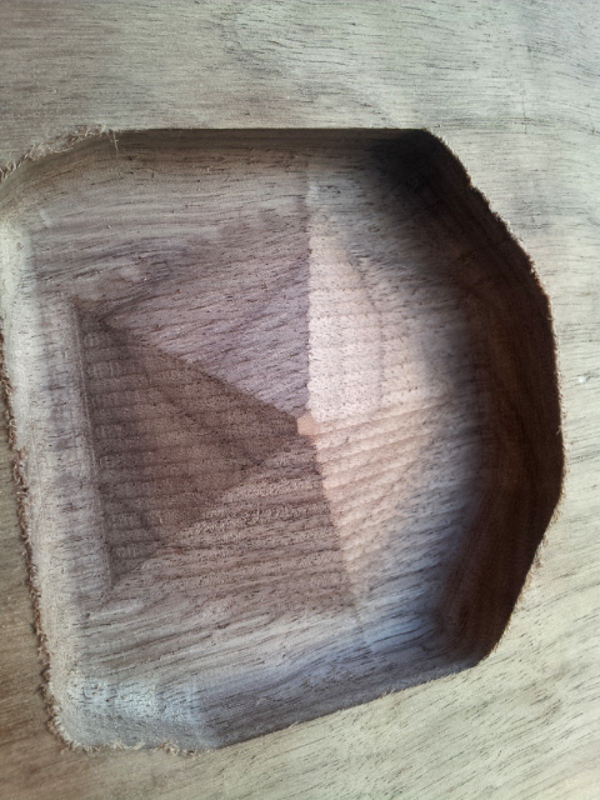
I am learning Viacad pro 7 as it is fairly robust 3d for $250 and not $2500 like a solidworks. Definitely demo before spending any money. I currently demoing Mesh Cam and Cam Bam and got both to make useable stuff. Mesh Cam does real 3d and I actually got it to make th part above without reading any manuals etc.
If it is any help to anyone wanting to understand steps to making a part via cnc, here is my workflow using "cheap" options as a cnc "newbie":
1. ViaCad Pro 7 for cad design
2. Export as STL
3. Open with Meshcam
4. Setup machining parimeters and generate tool paths
5. Export gcode
6. Open gcode in Mach3 and zero
7. Cycle start
-
09-06-2012, 03:32 PM #49
Registered
- Join Date
- Mar 2010
- Posts
- 156
Thanks for the kind words. I have learned so much on this site. Originally Posted by Mad Welder
On that note, I was able to make something in 3 dimensions. I drew a 5 sided pyramid in ViaCad Pro and actually got it to come out as a part. Learning this side of things is proving more challenging than converting the mill to cnc as well as finding useable cost effective CAD/CAM solutions.
VIDEO:
I am learning Viacad pro 7 as it is fairly robust 3d for $250 and not $2500 like a solidworks. Definitely demo before spending any money. I currently demoing Mesh Cam and Cam Bam and got both to make useable stuff. Mesh Cam does 3d easier for me and I actually got it to make the part above without reading any manuals etc.
If it is any help to anyone wanting to understand steps to making a part via cnc, here is my workflow using "cheap" options as a cnc "newbie":
1. ViaCad Pro 7 for cad design
2. Export as STL
3. Open with Meshcam
4. Setup machining parimeters and generate tool paths
5. Export gcode
6. Open gcode in Mach3 and zero
7. Cycle start
Any suggestions improvements etc would be appreciated. I am really learning as I go so ymmv :P
-
09-07-2012, 06:10 PM #50
Registered
- Join Date
- Jul 2012
- Posts
- 0
Since it looks like you already invested in ViaCad Pro, my suggestion probably won't mean much. If you are experiencing limitations or challenges with MeshCam and have a little extra money, I'd suggest Alibre CAD PE Edition ($299) with Alibre CAM Standard ($1,000). I am actually using Alibre PRO version ($1,000) and did a lot of CAM research earlier this year. I basically determined that the Alibre CAM (which is Visual Mill software) was the easiest and most powerful option I had for the money. Some of the parts I plan to machine are not easy to do in 3-axis and I would have to do machining in sections and stages. I demoed BobCam (ugly), DolphinCAM (limited), EZ-CAM (which really isn't easy at all), SurfCam, VisualMill (which had problems importing STEP correctly). Actually, the one challenge I saw with CAM programs was file compatability (such as STEP, STL, iges, etc.) The AlibraCAM is wrapped into Alibre as an extension of the software, so you won't have any geometry problems with file formats.
I did review one CAM software that I was extremely impressed with and that was TopSolid. However, for a 3-axis setup it would probably be closer to $10k or so. That software was pretty much as close to perfect as you could get. I did not review other high-end stuff like MasterCam, GibbsCAM, etc.
I did not try out MeshCam, so I don't know it's functionality. If you are machining something simple with no tool changes or just want a one-shot machining, it may be fine. I don't know what kind of stuff you are designing and whether ViaCad or Alibre or Rhino3D would be the best choice. Rhino appears to be better for doing free-form shapes like auto bodies, etc. Alibre is probably better if you're doing mechanical design (like mechanical parts such as brake assemblies, etc.).
-
09-13-2012, 04:31 PM #51
Registered
- Join Date
- Feb 2011
- Posts
- 605
So did you do your belt drive conversion like Gary, where you flipped that driver shaft and turned the gear off of it? If so how did you go about holding it in place, a nut like Gary, or a snap ring like Jermie used? Can you snap some pics up there.
I am starting work, at a slow pace up in the belt drive power drawbar area of my machine.
Overall things are looking good though. You got it done way quicker than I did.PM-45 CNC conversion built/run/sold.
-
09-13-2012, 06:22 PM #52
Registered
- Join Date
- Mar 2010
- Posts
- 156
The tube is held with snap rings on the underside of the head and on top where the bearings are. The pulley sits on a spacer is currently held by gravity. I had a crash with my jet 13x40 lathe and so power feed/threading is killed. I am going to cnc it as a result:P Anyway, things are basically gary's design without threading the top of the tube so far. I will probably thread it when I can but the pulley runs smooth and it isn't going anywhere. Originally Posted by jid2
Also, consider upgrading your bearings for the pulley tube and your spindle day one. My machine is running at 7700 rpm and the stock bearings smoked at that speed the first time I ran it that fast with the stock bearings.
Here is what I got:
(1) 7206CYP4 Nachi Angular Contact Bearing 30x62x16 Abec-7 Japan Ball Bearings
(1) 7207CYP4 Nachi Angular Contact Bearing 35x72x17 Abec-7 Japan Ball Bearings
(2) 7007B Angular Contact Bearing 35x62x14 Ball Bearings
I will try to post some more pics of the pulley setup.
Mark
-
09-14-2012, 01:42 AM #53
Registered
- Join Date
- Feb 2011
- Posts
- 605
Cool, I already have AC bearings ready to go, but I got the ABEC 3's, and might cowboy up to the ABEC 7's. Not sure yet. Jermie used the ABEC 3's.
PM-45 CNC conversion built/run/sold.
-
09-20-2012, 03:01 AM #54
Registered
- Join Date
- Mar 2010
- Posts
- 156
I ended up making a new stand for the PM45 CNC mill conversion. The other stand was solid but would rock under rapids and was too tall for where I am going to put the mill with the flood enclosure I am making. If you are doing one of these conversions, make sure you build a good stand with leveling feet that can handle the momentum of the table, especially during rapids.
Here is the old stand:

The new stand is 4" x 4"x 1/2" thick tubing with 2"x 2x 1/4" thick crossmembers. The top is 3/8" thick 30" x 30" and weighed 96lbs by itself. All in all, I got 422lbs worth of steel from the rems pile at industrial metal supply at 68 cents a lb.
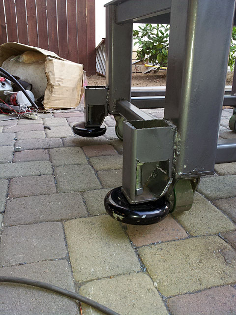
I added 6" steel casters and it rolls really nice even though it is over 400 lbs. Added Barrymount Leveling Mount LM5-B isolation pads that are 6" diameter and weigh over 5lbs each. they are offset the wheels so you can roll the mill around and then level the table after you get it where you want. I will be mounting the flood enclosure on top of the stand.
Pics:
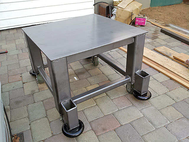
retractable levels:
It was a pain cutting that much thick steel. Plasma cutter got a workout. Thanks for looking...
-
09-20-2012, 03:31 AM #55
Gold Member
- Join Date
- Apr 2009
- Posts
- 5516
With such a kickass machine, I would defintely give other CAM software a look-see. You'll soon find the limitations of using STLs to create parts, especially if you need to control your toolpaths - i.e. to drill holes, pocketing, bosses, 3D surfacing - and these can all be on the same part. I did at one time use Cut3D for doing surfaces, then switch to Cut2D to do pockets and profiling, but then I'd have to make both 2D and 3D drawings of a part... Originally Posted by aaron2496
I demoed VisualMill and it is powerful and easy to use. SurfCAM is nice but not $10K nice. SprutCAM looks good but never demoed it. I did not like BobCAM but I've seen lots of cool stuff made with it. I ended up going with OneCNC which was so easy to use I did complex toolpaths without reading the instructions, and preferred the machining "wizards" over the dropdowns in VisualMill. It is slightly easier, however to manipulate objects in VisualMill.
-
09-20-2012, 04:35 AM #56
Registered
- Join Date
- May 2004
- Posts
- 600
Just out of curiosity, what are the heights of both stands (old and new) from the ground?
-
09-20-2012, 08:15 PM #57
Registered
- Join Date
- Mar 2010
- Posts
- 156
The original stand is 30" tall that I made and the new one is 23" tall. With a manual machine you are standing and cranking all the time and you don't do that with the cnc. The other thing is lower center of gravity is better. Originally Posted by skippy
-
09-26-2012, 03:22 PM #58
Registered
- Join Date
- Mar 2010
- Posts
- 156
Update: I got xyz touch off probing to work. Thanks out to erniebro and this thread:
http://www.cnczone.com/forums/mach_w...tml#post436238
I installed the Mach Blue Probing by Big-Tex screen set and got it to work with the DMM tech DMB4250-8B Breakout board. I need to make an electrically isolated probe next so the stock doesn't need to be taped up, but the probe works. For connections, I connected a wire from the DMB4250-8B Breakout board's "a limit" in and vout terminals to make the circuit and then used the following settings under input signals in ports and pins in mach 3:
Probe:
Enabled
Port#1
Pin# 13
Active low
These settings worked with the dmm tech board. I know this has been out on cnczone for a while but it is still awesome.
Video:
-
10-15-2012, 03:40 AM #59
Registered
- Join Date
- Mar 2010
- Posts
- 156
Update:
I added an ethernet smooth stepper to the DMM Tech servos and it worked just fine. I needed additional imputs beyond the DMM tech board's for touch probe + hall sensor based tach and spindle speed control etc.
I was able to use the a limit input on the DMM tech bob for either a probe input or a spindle tach with a hall sensor but not both. Adding the Smooth stepper, I gained 2 more parallel ports worth of inputes + extra precision and reliability of a dedicated motion control board.
I also started work on my flood enclosure. First I had to make a bending brake. The bending brake is basically 3 6ft 1/4" angle iron pieces, some black pipe and 2 3/8 thick pieces for the arms. Plans I got from here:
www.ch601.org/tools/bendbrake/brakeplans.pdf
Pics:
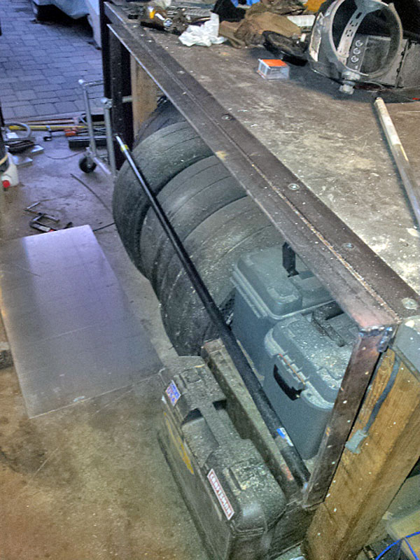
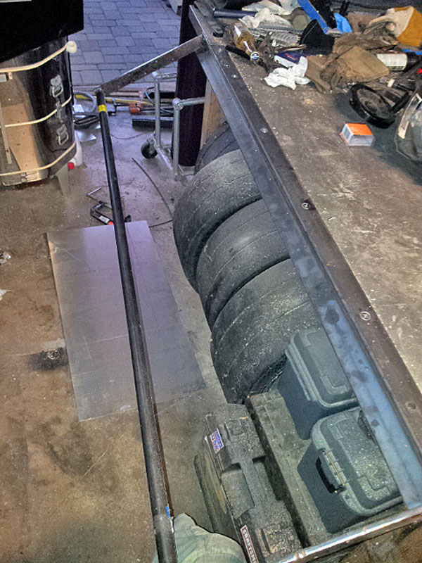
I could bend 1/8" thick aluminum just fine:
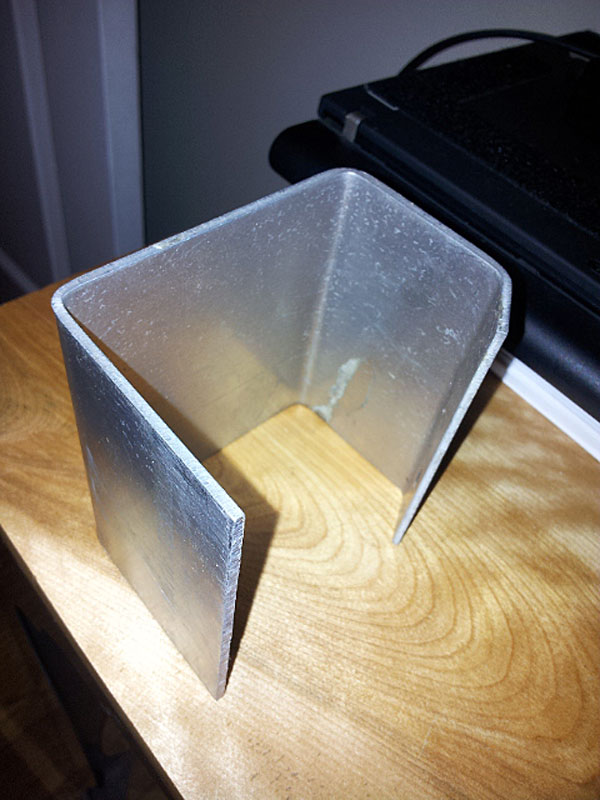
This was the first time I ever bent sheet metal but the brake works great:
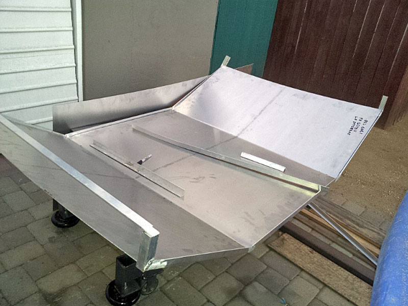
I can't wait to finish the flood enclosure so I can start taking the Mill apart and putting it on the new stand with everything in a permanent setup.
-
10-15-2012, 04:03 PM #60
Gold Member
- Join Date
- Jan 2010
- Posts
- 2141
What material are you using for the flood enclosure?
Is the flood enclosure of your own design (and if so, would you be willing to share dimensions), or else could you provide a link to the plans that you are using? I have seen some plans on cnczone in the past, but I'm not sure exactly where - perhaps they were buried inside one of the Tormach threads.

 Reply With Quote
Similar Threads
-
An Aussie IH Clone Build (Long Travel RF45)
By Wallerawang in forum Benchtop MachinesReplies: 91Last Post: 08-28-2014, 10:22 AM -
What RF45 clone should I get?
By Nigel Tufnel in forum Benchtop MachinesReplies: 2Last Post: 12-03-2013, 06:24 AM -
Build Thread: HF 8x12 variable speed DC motor conversion
By gt40 in forum Mini LatheReplies: 1Last Post: 04-13-2010, 10:16 PM -
X3 or RF45 clone?
By logjammer in forum Benchtop MachinesReplies: 13Last Post: 12-14-2006, 03:34 PM -
convert rf45 type to belt variable speed and some cnc info?
By ataxy in forum Knee Vertical MillsReplies: 20Last Post: 09-03-2006, 04:58 PM
