


Hey,
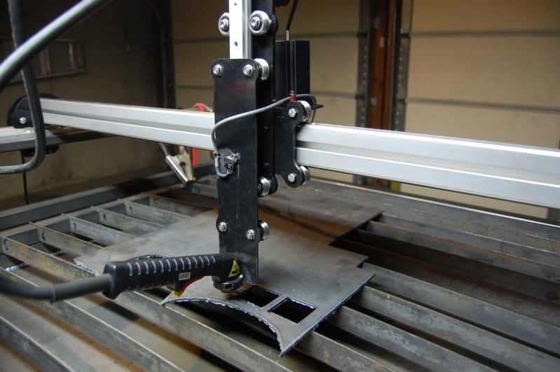
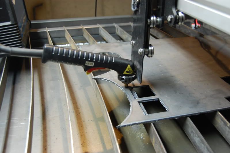
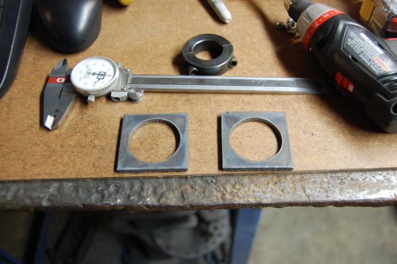
Well my build has been going on for a few months now. I finally have the table in a place where I have been making test cuts! Woo hoo! Ive really not used my plasma much in the past year of having it so I just now destroyed my first electrode believe it or not. Needless to say I have a few days of down time until my new consumables come in...Perfect time to share some pics!
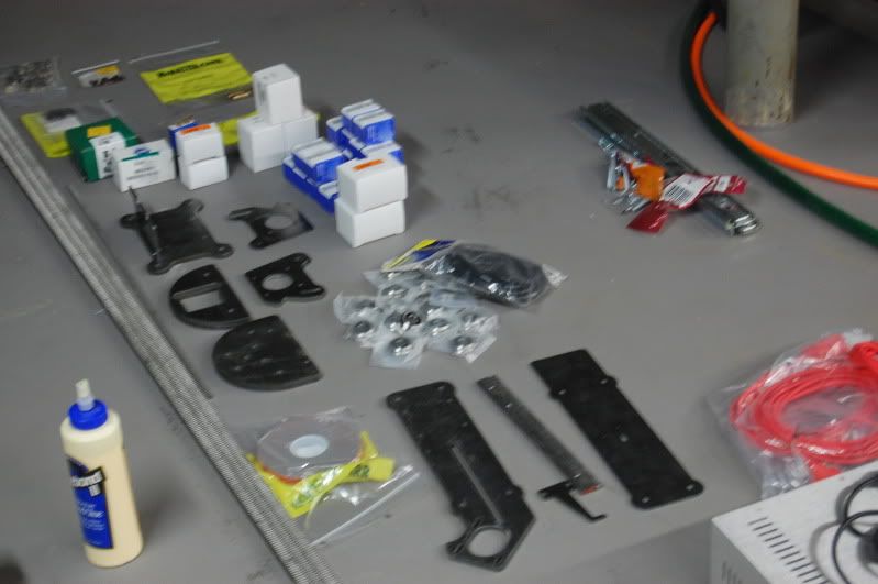
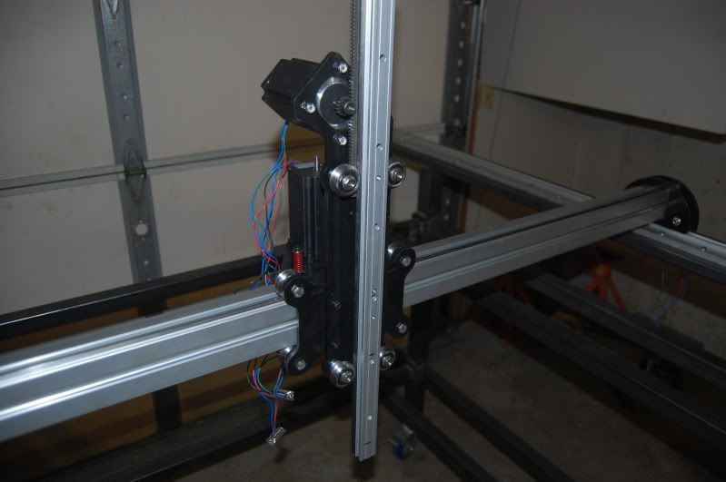
Anyway, about my build.... I decided to go with the plasmabot 3.0 kit. I ordered just about everything for the kit including the floating z-axis, dust covers and the spring attachment. I ended up using everything but the spring attachment...I really only think this is needed with a router setup, my motors seem to do fine lifting my plasma.
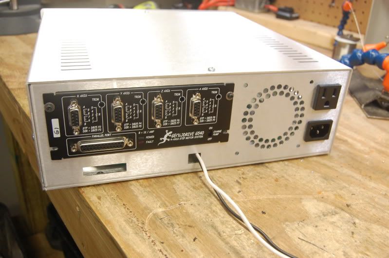
I got the steppers and motor controller from www.kelinginc.net. I ordered the 4 axis g540 package (381oz motors). I also picked up the aluminum controller box they sell. I also go the parallel and heavy duty serial cables from www.cncrouterparts.com. I completed the controller box first while waiting for my rails to arrive (which took two months btw). Here are a few pics of the controller box:
The only thing I thought was a bit tricky in the controller box was setting up the torch relay. At first I didn't realize you could use any voltage relay so I kept looking for 48V relays. I had a 5V DC 240V 30A solid state relay on hand and wanted to use it. I figured out that if you supplied it with its own power you could throw it with the controller quite easily. The power supply is a small 5V wall adapter removed from the case. You can see this on the first pic, left side.
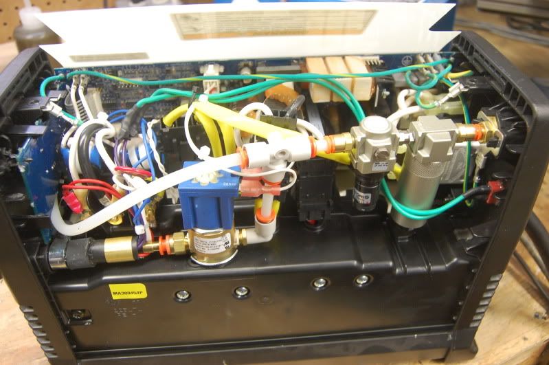
I wanted to still use the hand torch from time to time so I just wired a plug into the case of the plasma cutter that would make the whole thing easy to disconnect from the table. Its a Miller 375 x-treme btw. I ended up just epoxying a plug on to the case.
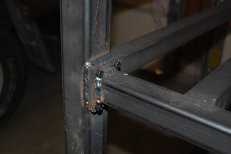
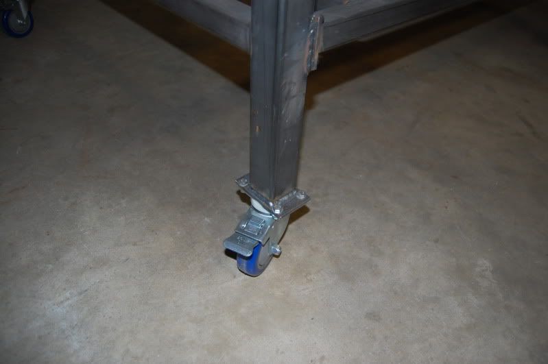
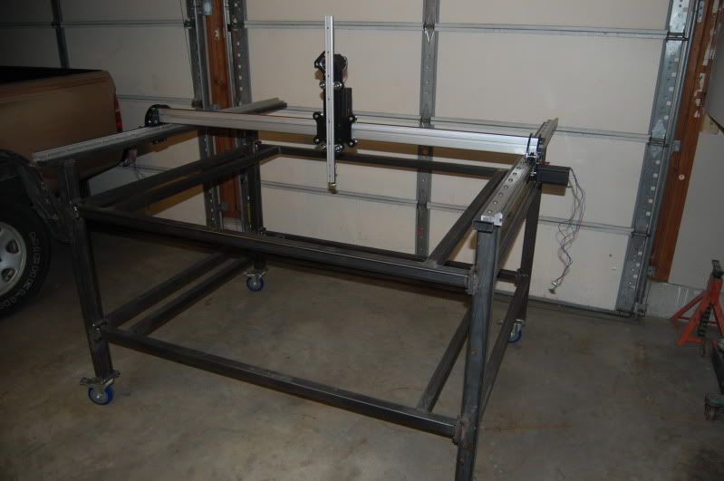
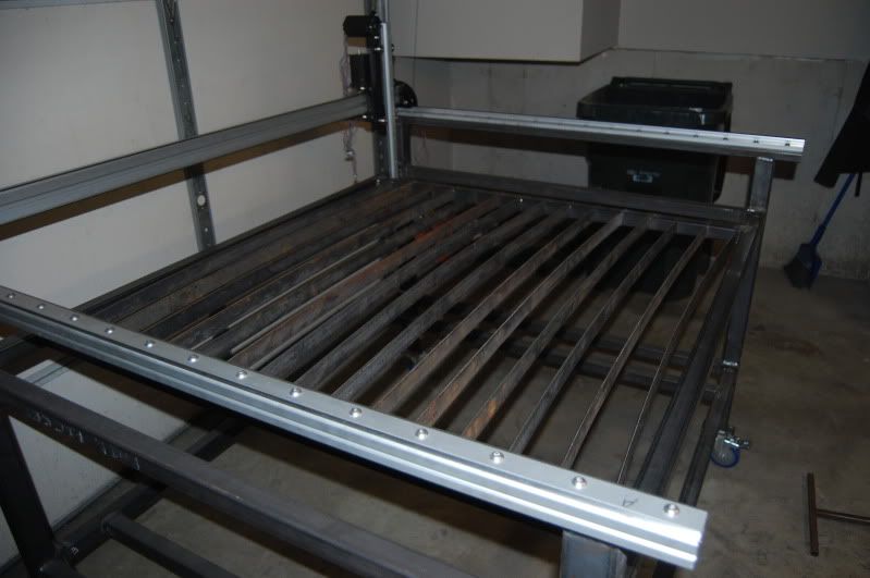
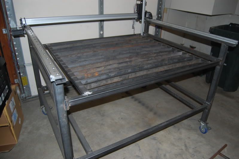
My table is almost the same as what the plasmabot plans call for with the exception of a few things. First I used 2"x"1/8" tubes only on the legs, everywhere else I used 1.5"x1/8" tube. The second change I made was designing the table so that it could be taken apart for moving. The two sides, water tray/slats and bottom level all come apart.
The last design change I made was to the slat system. The plasmabot calls for a complicated interconnected slat design that has to be cut out from sheet each time they need to be replaced. I wanted to avoid this hassle so I just used 1.5"x1/8" flat stock with a slight curve in them. Every few inches a slot has been cut to allow the slats to sink into the tube. Now...this wasnt and ideal design as water can get into the tubing however I decided that I would be going more for cut quality so I may never fill the water that high anyway. We shal see how it works out...
I created the water table from a 44"x44" sheet of 1/8" steel. The sides were created from 1.5"x1/8" flat stock. The entire table is welded to the underside of the top section. I didnt worry about making the tray removable since the entire top section can be removed if needed.
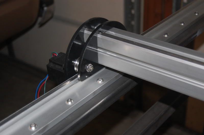
I used a shaft collar to attach the torch to the z-axis. It is currently just tacked in. I made a few test cuts and the angle seems to be a bit off so once I get some new consumables I am going to cut it off and re-tack it or either think about making some kind of adjustable fixture for the torch so that I can easily align it.
Some of my todo's are to install a drain plug for the water table, paint, route cables, build a computer stand, etc.. Ill keep posting as I have more.
Thread: My Plasmabot build
Results 1 to 20 of 25
-
01-04-2012, 09:47 PM #1
 Registered
- Join Date
- Sep 2007
- Posts
- 64
My Plasmabot build
-
01-26-2012, 05:38 PM #2
Registered
- Join Date
- Sep 2007
- Posts
- 64
I have completed my computer stand. I didnt want to attach it to the machine because I often have to rearrange my shop. I will eventually place a piece of oak on there for the keyboard/mouse tray; the plywood is temporary.
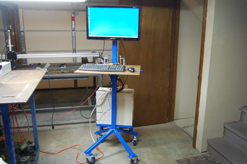
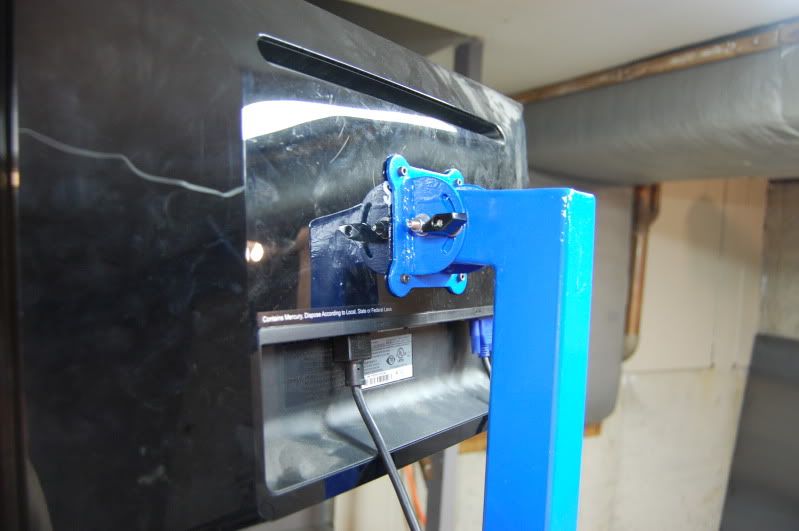
I made the monitor adjustable...although it really didnt need to be. Kind of an excuse to use the plasma cutter.
-
01-26-2012, 06:10 PM #3
Registered
- Join Date
- Jun 2010
- Posts
- 178
Nice work, looks clean and well put together. Also good results! Keep pictures coming
-
01-27-2012, 03:51 AM #4
Registered

- Join Date
- Mar 2010
- Posts
- 0
Do you have a part number for the harden vrail? Or a price it cost just rough estimate...I am sitting here with my credit card thinking trying to decide if I want the 3.0 or the 4.0...went to a supplier today and they said the v rail was discontinued...but thinking they were looking at the wrong thing..I like the way you mounted yours also...looks good
-
01-27-2012, 02:46 PM #5
Registered
- Join Date
- Sep 2007
- Posts
- 64
IVTAAG, IVTAAS and IVTAAN. Be warned though...It takes about two months to get the IVTAAG rails.
I paid:
VTAAG x1, 64.5" - $149.91
IVTAAS x2, 62.5" - $104.53 each
IVTAAN x1, 23" - $24.47
-
04-17-2012, 09:00 PM #6
Registered
- Join Date
- Sep 2007
- Posts
- 64
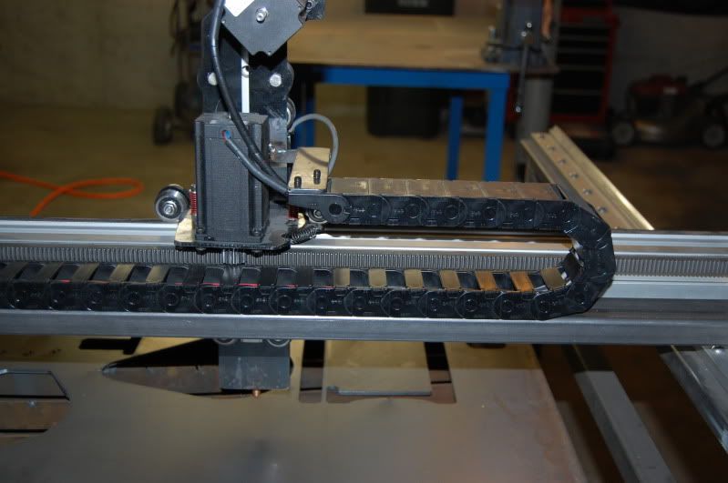
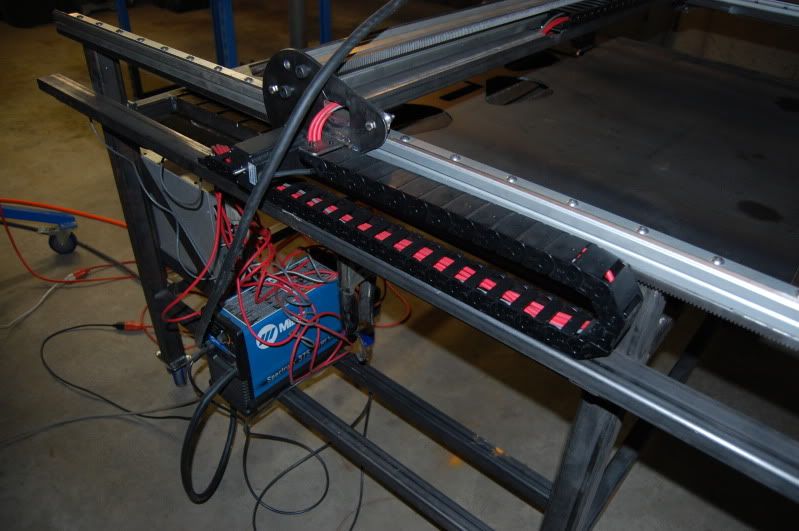
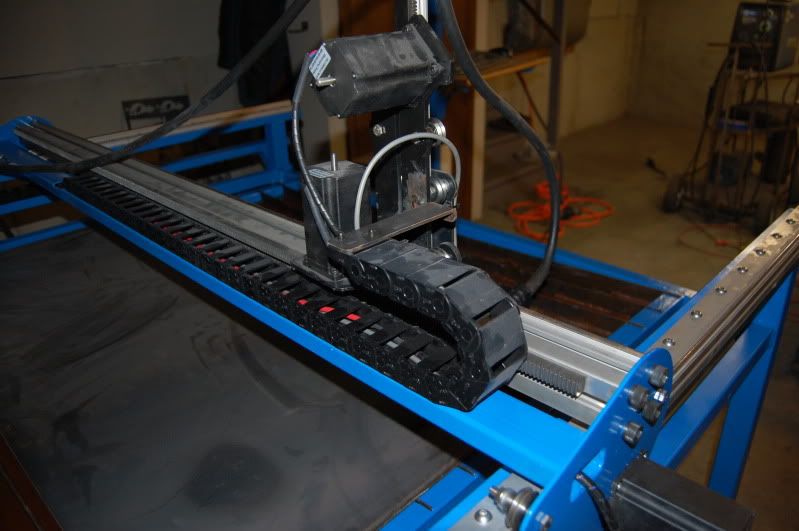
Just an update on my build. A few months ago I purchased some igus cable chains. Its been a long delayed project getting them installed because of the work I wanted to do but its done!! Here are a few pics of the current progress.
I didnt want to mount a bracket to the gantry rail. I wanted to install a separate bar to that would span the length of the gantry so I needed to re-create the gantry plates first. I only had 1/8" plate on hand but it seems to work well so I rolled with it. Once the new plates were cut, installed and tested I attached the tubing.
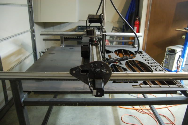
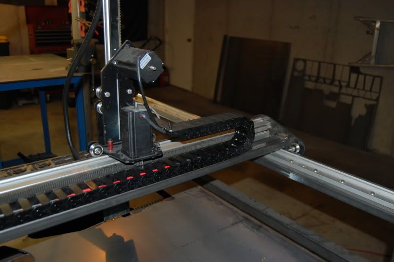
The nice thing about the tubing is that it adds a bit of weight to the gantry and it allows for a channel that the cables can pass through while also having a mount for the cable chain.

I still need to organize the cables a bit and also install a plug for the touch-n-go switch wire but its looking pretty good I think.
Also got the oak keyboard and mouse rest installed.

Who knows how long it will take me to get around to painting this thing but it will be the same color blue as the stand. Thanks for looking!
-
04-17-2012, 10:21 PM #7
Registered
- Join Date
- Oct 2010
- Posts
- 317
Looks great! :cheers:
-
04-18-2012, 12:02 PM #8
Registered
- Join Date
- Nov 2007
- Posts
- 250
Ingus Cable chains really are nice. They make a more professional build.
One thing jumps out at me when I looked at your machine...
Get a thin piece of material and cover the plasma unit and power supply. The sparks and slag are going to burn holes in the wires.
You don't need those problems after you use the machine for a while.
Good Job.
aj
-
04-18-2012, 03:12 PM #9
Registered
- Join Date
- Sep 2007
- Posts
- 64
aj,
This is a good idea. Something else I almost noticed the hard way was that moving the table while the water tray is filled caused the water to slosh around quite a bit. I almost ended up with a big splash of water right into my control box so I will be building some kind of protection for the box and exposed wiring at some point.
-
04-18-2012, 08:40 PM #10
Registered
- Join Date
- Feb 2012
- Posts
- 69
This is the closest to my build and there's some good info here. I am also using PlasmaBot 3.0 Ultimate Gantry Kit, but I have gear reduction. Same Z-axis, same rails and even same electronics package and cotroller enclosure, with exception of I added the LCTHC from CandCNC. Other exception, I am building a 4x8 clear table so I can burn a full sheet of steel if needed.
I will keep you posted on this - hey, did you ever add a cooling fan to your control box? I think it might be essential for complex jobs - might get a bunch of heat buildup in there.
I am waiting for my V-rail to arrive any day now and will get started. Where did you source your cables? I am trying to compile all this into one thread for tihs site, so I might add your cable source there too.
-
04-18-2012, 08:53 PM #11
Registered
- Join Date
- Oct 2010
- Posts
- 317
What are the dimensions for that enclosure box? I didnt see any on the website. Thanks.
-
04-18-2012, 10:50 PM #12
Registered
- Join Date
- Nov 2007
- Posts
- 250
Hello, Originally Posted by Nacs Fab

I bought a lot of wire / cables for igus.. They have a great selection and are easy to deal with...
More often than not.... they had the best price too.
Check them out..
aj
-
04-18-2012, 10:58 PM #13
Registered
- Join Date
- Sep 2007
- Posts
- 64
I got my cables from CNCRouterParts. I used the plastic db9 connectors that the gecko g540 comes with and connected them to the cables via those at first but I quickly found that they would cause my cable chain to bind and snap apart. I ended up having to cut one end off and wire my steppers directly to the cables. Given this it might be easier to just get some nice shielded cable (or larger cable chain). I found the cable chain on ebay (DougDeals.com) was the seller.
I did not put a fan in my controller box but I do notice the gecko does get pretty warm. I have been thinking about adding a PC heatsink and fan to the back of the gecko case.
-
04-18-2012, 11:06 PM #14
Registered
- Join Date
- Oct 2010
- Posts
- 317
What exactly was binding the cable chain? Originally Posted by HakBot
-
04-18-2012, 11:08 PM #15
Registered
- Join Date
- Sep 2007
- Posts
- 64
My cable chain was about 1"x2" on the outside...just enough for a db9 plug and a few other wires to fit it so it was pretty cramped. When two DB9 connectors are together they are about 3"-4" long and do not flex....so the cable chain cant bend and ends up snapping apart or the cables disconnected.
-
04-19-2012, 03:05 PM #16
Registered
- Join Date
- Feb 2012
- Posts
- 69
I linked to the page on the Keling (sp?) website in my Electronics post in this forum. Originally Posted by tjb1
CNC Controller | Stepper Motor Controller
Scoll down to near the bottom and you will see the aluminum enclosure. Its real nice - it comes with all of your power connections, a on/off switch, E-Stop and its even pre-labeled in these locations. It has a few extra openings for DB-9 connectors and has a Fan opening. Oh, it also has the opening for the G540 controller. Well worth the $79 in my book.
I am going to modify mine to also house the LCTHC I bought from CandCNC. Sorry for the thread hijack.
-
04-19-2012, 03:24 PM #17
Registered
- Join Date
- Oct 2010
- Posts
- 317
Ive been there, I dont see any dimensions for the box. Originally Posted by Nacs Fab
-
04-19-2012, 03:54 PM #18
Registered
- Join Date
- Sep 2007
- Posts
- 64
The controller box is roughly 13"x13"x4". I agree its a nice box and it goes great with the gecko g540. I actually ended up buying two of them and replacing the box I used on my Taig mill. I am using a xylotex controller with it so I had to make a custom plate to cover up the hole made for the gecko.
-
06-27-2012, 02:42 PM #19
Registered
- Join Date
- Sep 2007
- Posts
- 64
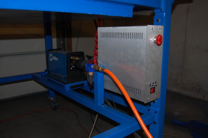
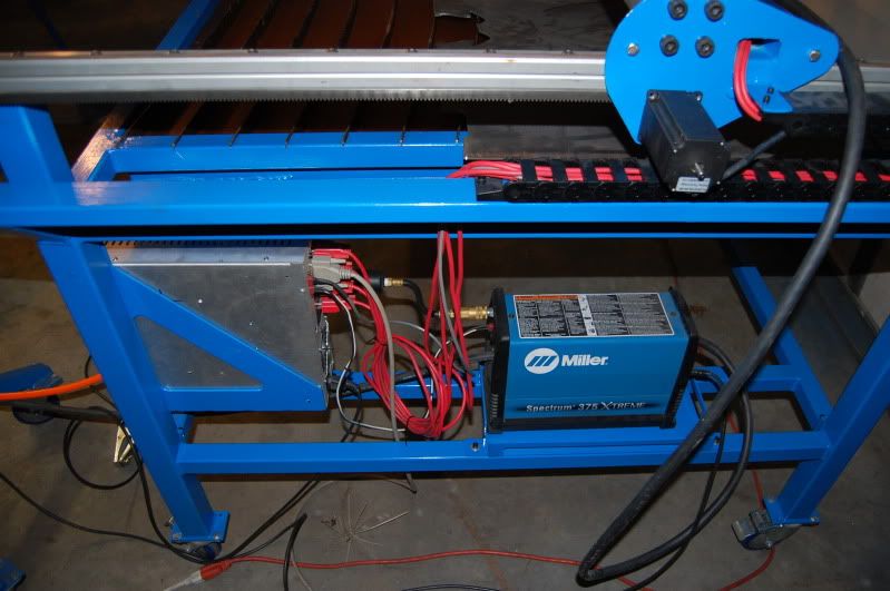
Well Ive got everything painted and put back together. I still need to do some work on getting the wiring all straight but for the most part its done.


-
06-27-2012, 04:47 PM #20
Registered
- Join Date
- Feb 2012
- Posts
- 69
Looking real good, ordered the steel for my table this week, hopefully we will be assembling mine soon. Got the control box done, you can view it under my post about compiling electronics in this forum. I actually mounted the LCTHC in the front face and it worked really nice!
How long is your IGUS chains on each axis?


 Reply With Quote
Similar Threads
-
Johns 4x4 Plasmabot 4.0 Build Thread
By johndjmix in forum Plasma, EDM / Other similar machine Project LogReplies: 87Last Post: 04-12-2013, 03:23 AM -
Starting my "PlasmaBot" 4x4' table build!!!
By winegar in forum Plasma, EDM / Other similar machine Project LogReplies: 340Last Post: 01-28-2013, 10:53 PM -
My PlasmaBot
By tulsaturbo in forum Plasma, EDM / Other similar machine Project LogReplies: 47Last Post: 07-12-2012, 02:16 PM -
DirtBound Offroad's PlasmaBot table build
By DirtBound in forum Plasma, EDM / Other similar machine Project LogReplies: 98Last Post: 11-29-2011, 06:52 AM -
Yet another "PlasmaBot" build :D
By cobretti in forum Plasma, EDM / Other similar machine Project LogReplies: 53Last Post: 07-11-2011, 01:19 PM
