


I recently deployed madCAM as part of my overall CAD/CAM strategy for a new K2 CNC system. I have to say that, with the exception of one workflow, the entire process was rather intuitive and relatively pain free ... and once I discovered how to perform that non-intuitive workflow, the entire process is rather easy and straight forward :banana:
I model my design in RhinoCAD
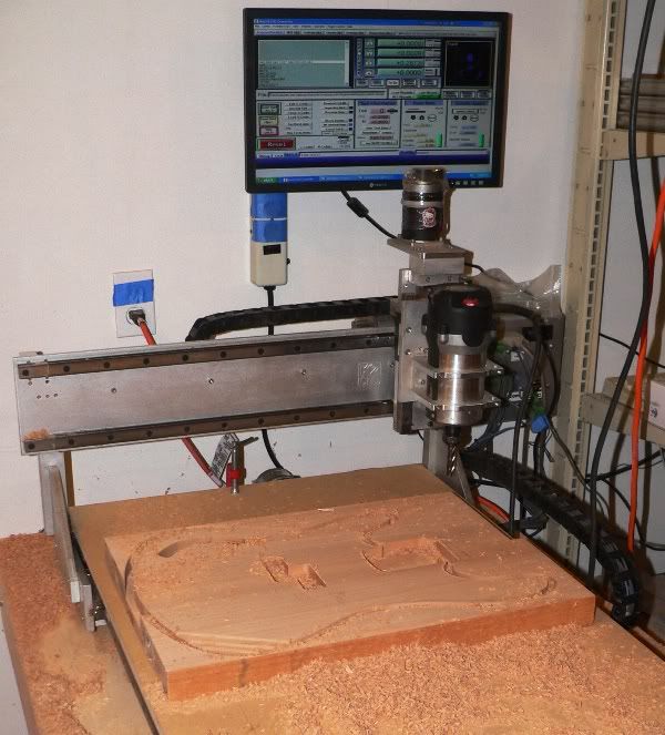
select the tools and define their paths with madCAM
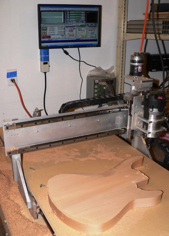
and then post the gcode. Mach3 utilizes the posted gcode files to drive the CNC just like it should
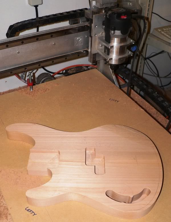
and the end result is a roughed guitar body that's ready to be finessed by hand into a playable work of art
all the best,
R
Results 1 to 18 of 18
-
10-20-2011, 06:26 PM #1
 Registered
- Join Date
- Oct 2011
- Posts
- 41
 madCAM for Luthery (guitar building)
-
10-20-2011, 10:29 PM #2
Community Moderator
- Join Date
- Mar 2003
- Posts
- 35538
Very nice 1st post. Welcome the the Zone.
 Gerry
Gerry
UCCNC 2017 Screenset
http://www.thecncwoodworker.com/2017.html
Mach3 2010 Screenset
http://www.thecncwoodworker.com/2010.html
JointCAM - CNC Dovetails & Box Joints
http://www.g-forcecnc.com/jointcam.html
(Note: The opinions expressed in this post are my own and are not necessarily those of CNCzone and its management)
-
10-21-2011, 12:23 PM #3
Community Moderator


- Join Date
- Mar 2004
- Posts
- 1661
What was the workflow you had problems with?
Either there might be an explanation or it could be a request for change if we ask for it. Enlighten me!
-
10-21-2011, 08:59 PM #4
Registered
- Join Date
- Oct 2011
- Posts
- 41
The madCAM workflow for defining the tool paths on the forearm and gut-cuts are significantly different than the workflow used by VisualMILL/RhinoCAM. During my 30-day eval period I dropped a quick note to Joakim requesting advice on how to perform this operation, and received a nicely detailed reply the following day
I wouldn't call it a bug, just a workflow difference in how the two CAM tools define a surface region to be machined
- in madCAM I need to include the contour surface as part of my solid model, and include a contour curve for the boundary I want to cut inside of. it's easy to extract a border from the feature face
- in the other tool, only the surface face is needed
since I prefer to model my part definitions as solids, I prefer the madCAM workflow over the other method
all the best,
R
-
10-23-2011, 12:02 PM #5
Community Moderator
- Join Date
- Mar 2004
- Posts
- 1661
R,
If you mean that you must select the boundary (Region curve) with the model, you don't have to. You can, but you can make the region on the fly when or if you need it.
As long as you get a process that is fine for your work, then it's all ok I believe.
-
11-01-2011, 08:43 PM #6
Registered
- Join Date
- Jan 2007
- Posts
- 36
Can you walk us through how you develop your model in Rhino in order to use MadCAM? I start with outlines generated in Autocad, import them into Rhino, offset them, generate the pockets and such, and make surfaces rather than solids. What's more efficient?
-
11-01-2011, 11:04 PM #7
Community Moderator
- Join Date
- Mar 2004
- Posts
- 1661
Was that a question to me or to Rodent? Originally Posted by CbrViking

if it was for me - I always keep my models as solids, even when I create surfaces I remake the solid to include that particular surface. With a solid you have better control of the "model body", analysis tools etc.
rhino:soliddiscussion · McNeel Wiki
The good thing with Rhino though, is that any object is accepted at the same time. You can have a solid, polygon and a loose surface together. It's very handy if you want to block a toolpath from an area to stretch out a temporary surface for example.
-
11-01-2011, 11:07 PM #8
Registered
- Join Date
- Oct 2011
- Posts
- 41
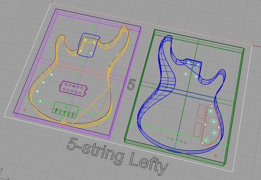
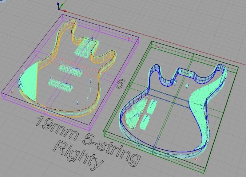
almost all of the MadCAM toolpaths can be generated from 2D curves in this design, the exceptions being
- the top side forearm contour
- the rear side gut-cut
- the rear side heel contour (where the neck is bolted on)
I create an extruded solid from the body contour, create the 3D surface for each of the contours above, trim the body solid with the contour surface, join it all back together into a closed volume, and then generate an outline curve for the contour face.
in MadCAM, select the body solid as your material, select the tool, and then select the contour as your machined area limitation boundary.
depending on the surface contour and your material offset preferences, you may be able to skip one of the two roughing steps (i.e. go right from roughing to machining the final surface)
make sense?
svenakela - it would be interesting to learn if you have any suggestions on simplifying this workflow
all the best,
R
-
11-01-2011, 11:21 PM #9
Registered
- Join Date
- Jan 2007
- Posts
- 36
Thanks guys - I'll try and figure out what you said... Sorry, I'm a total newbie to both Rhino and MadCAM.
-
11-01-2011, 11:50 PM #10
Registered
- Join Date
- Oct 2011
- Posts
- 41
if you already know AutoCAD, take the time to organize your layers well before migrating your work to Rhino. if you need to do any clean-up in Rhino once you data is there, take the time to do so before you go any further Originally Posted by CbrViking
I'm a novice Rhino user from the viewpoint of total hours used .... but I have been a CATIA consultant for over 10 years, and have used several other CAD packages the past 20 years. all of my composites and advanced surfacing activities provide me the foundation to know what I need to do ... then it's a simple matter of learning the workflows for a particular CAD or CAM package.
having tidy work habits that include regular backups will also go a long ways towards making your life with any CAD or CAM package easier.
all the best,
R
-
11-02-2011, 11:37 AM #11
Community Moderator
- Join Date
- Mar 2004
- Posts
- 1661
As a note for Rodent, you cut mostly in soft materials so you can go from roughing to a fine pass. For example Z-leveling is very important if you cut in metal and next tool is prone to snapping (small, long, ball etc), the Z-level path makes next cutter work with constant depth. If you go from roughing directly to a fine path a similar tool will snap right away.
When working in soft materials though, there's not a problem if the cutting depth varies.
-
11-02-2011, 03:18 PM #12
Registered
- Join Date
- Jan 2007
- Posts
- 36
Svenakela - that's great advice. I do mostly wood routing, but I do have a design for a guitar bridge in aluminum that I will eventually get to.
Rodent - I recently discovered layers in Rhino and they help a lot! I use them all the time in Autocad, so it was nice to see them in Rhino.
-
11-02-2011, 06:37 PM #13
Registered
- Join Date
- Oct 2011
- Posts
- 41
svenakela - good clarification. I was thinking specific to wood, but didn't make that clear in my postyou cut mostly in soft materials so you can go from roughing to a fine pass
all the best,
R
-
11-27-2011, 06:58 PM #14
Member
- Join Date
- Feb 2008
- Posts
- 4
limiting toolpath area?
I'm a rank beginner at Rhino and Madcam so I'm glad to find this discussion.
I'm attaching an image of a bass stick I'm making, most of which I already have toolpathed for 2D and would like to limit Madcam to the 3D surface of the neck areas. How do I go about that without it trying to cut to the table height at the ends?
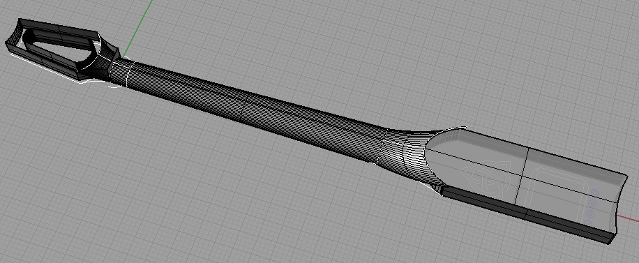
This is probably in one of the PDF tutorials but I haven't come across it yet.
Any tips appreciated.
Thanks
David
-
11-27-2011, 08:10 PM #15
Community Moderator
- Join Date
- Mar 2004
- Posts
- 1661
Regions and clipping planes. See clips below.
Clipping planes and extended stock model in madCAM - YouTube
Making regions in MadCam - YouTube
EDIT: You can make a simple "clipping plane", add a surface at the lowest level you want to cut. Make sure it is bigger than the region curve you will use. Reselect the model with the surface and then add the region curve. By doing this you've restricted the Z-level for the toolpath. i use this procedure when I need a clipping plane that is bent, angled etc.
-
11-28-2011, 04:10 PM #16
Member
- Join Date
- Feb 2008
- Posts
- 4
I've watched those videos. Clipping planes don't seem to do the trick as I want to mill the neck region down to zero of the surface. The body and peghead I want to "mask" are 1.25" high. I've tried making a "region curve" but when I try to use it, it won't allow me to select it. It's a closed polyline. Isn't that right? Here's a sketch of it.
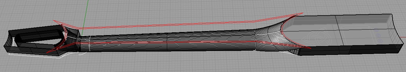
I've tried positioning that region curve at the base and at the top of the work piece and enlarged it to allow for cutter diameter, but still it won't allow me to select it.
Thanks again for your help.
David
Originally Posted by svenakela
-
11-28-2011, 07:01 PM #17
Moderator
- Join Date
- Apr 2003
- Posts
- 1357
Are you sure it's closed? Try using the CloseCrv command and see if it does anything. Or try CrvStart (or CrvEnd) and zoom into the point to see if it's really closed.It's a closed polyline.
Dan(Note: The opinions expressed in this post are my own and are not necessarily those of CNCzone and its management)
-
11-29-2011, 04:56 AM #18
Member
- Join Date
- Feb 2008
- Posts
- 4
Thanks Dan...
You were right Dan, my region curve wasn't closed. Fixing that made it work quite nicely. I had to keep it pretty spot on the size and shape of the neck milling area to prevent it from cutting off the ends, but it looks good now. I'll let you know how it cuts.
Thank you, and Sven for your help.
I ultimately would like to model a near replica of a neck of an old Martin D-28S I used to have. This success at a simpler form has made me hopeful.
All the best.
David
David Beede's home page - more quasi esoteric folk stuff on assorted semi-obscure instruments...
Originally Posted by Dan B

 Reply With Quote
Similar Threads
-
building a cnc guitar pickup winder, need info
By yorttroy in forum Musical Instrument Design and ConstructionReplies: 40Last Post: 04-07-2012, 01:58 AM -
CNC Guitar Building Instructional Videos
By sagreen in forum Musical Instrument Design and ConstructionReplies: 7Last Post: 02-12-2011, 02:22 AM -
CNC Guitar Building CAD/CAM Services
By dishawcues in forum Musical Instrument Design and ConstructionReplies: 3Last Post: 02-11-2010, 08:28 PM -
3d cad cam for guitar building
By belgrado in forum Uncategorised CAM DiscussionReplies: 0Last Post: 12-05-2006, 10:34 PM -
Building an electric guitar by hand
By cncadmin in forum Musical Instrument Design and ConstructionReplies: 1Last Post: 06-09-2003, 06:22 PM
