


Of course, I have to be different. Who knows why. Apparently I'm using somewhat larger switches than other folks are using so some of the possible locations don't work for me.
But, what I got is simple enough.
First rule. All switches will bypass the carriages. In other words, you won't slam into the switches and damage them, you just run past and damage something else.
X and Y are simple enough. The X and Y mounting boards are the same. For the X, I match drilled the mounting holes and installed #6 T-Nuts from the back side. Thus, you can install and remove the switch mount plates without removing all the electronics from their cavities.
The ridiculously long screw protruding the the T-nut to the right is temporary mounting for the power supply on the back side.
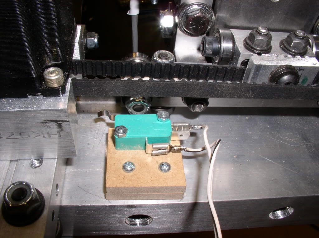
The Y is similar, but I could match drill and tap the gantry tube. I'm indexing off the locknut for one of the bearings. I don't much like that, but it works fine.
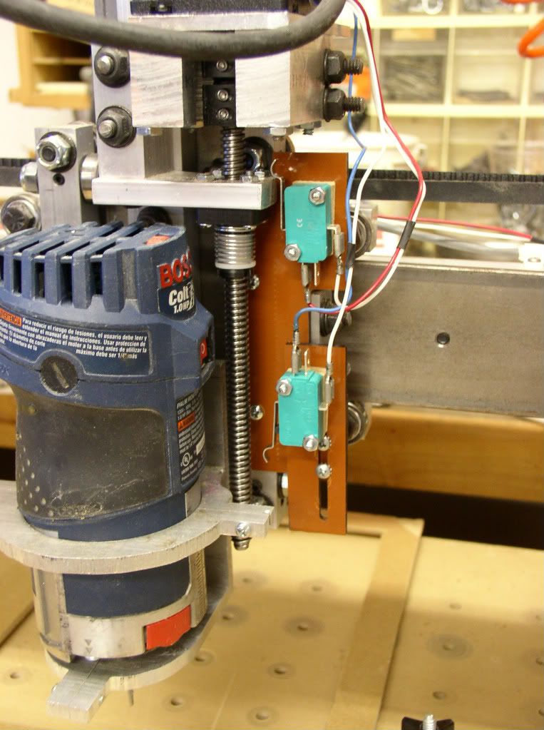
The Z is not simple. I designed this about the same time as Bob did for the switches in his post. I decided to index off the mount for the acme nut. The mounting plates are 1/8" phenolic. The main plate needs to miss a few things, so its not a simple shape. It has to miss washers under the right bearing block and also miss set screws for other adjustments. When I was done, the upper home/limit switch wasn't forward enough to hit the acme nut block, so I spaced it out with a 1/4" MDF shim. The lower limit switch is adjustable. It needed spacing out 1/2" as well but that is to decomflict the wiring so as not to short out anything.
Thread: Michael's Limit Switches.
Results 1 to 3 of 3
-
10-11-2011, 01:42 AM #1
 Registered
- Join Date
- Apr 2011
- Posts
- 121
Michael's Limit Switches.
-
10-11-2011, 02:00 AM #2
Registered
- Join Date
- Mar 2011
- Posts
- 144
How do those clamps work for you ?
-
10-11-2011, 03:13 AM #3
Registered
- Join Date
- Apr 2011
- Posts
- 121
Adequate. I need about another 1/8" offset and the router hits a mounting screw. Good enough for some test cuts and to make new mounts. These are just hacked out of scrap aluminum plate. Originally Posted by fastpcuser

I have a design for a new mount, just have to get a few odds and ends done so I can cut them. Probably this weekend.


 Reply With Quote
Similar Threads
-
Home switches and Limit Switches
By TheBulk in forum DIY CNC Router Table MachinesReplies: 5Last Post: 03-12-2011, 12:08 PM -
Limit switches and homing switches
By AeroKam in forum Open Source CNC Machine DesignsReplies: 16Last Post: 01-05-2008, 02:56 PM -
The relationship of limit switches to home switches.
By MikeAber in forum CNC Machine Related ElectronicsReplies: 4Last Post: 11-04-2004, 08:28 PM -
Limit switches and home switches
By viktorcnc in forum CNC (Mill / Lathe) Control Software (NC)Replies: 2Last Post: 08-03-2004, 12:11 PM -
Home switches and limit switches.
By ynneb in forum CNC Machine Related ElectronicsReplies: 5Last Post: 04-08-2004, 11:32 PM
