


Disclaimer: This is not a standard Momus build. It is not in my nature to leave well enough alone. Even though this is a well developed plan I have altered or redesigned parts to fit my needs, wants or methods of work. Bob has done an excellent job with these plans and unless you like making extra work for yourself, building to the plans is probably best. But, I can’t, so here we are.
Also, please comment. Positive and negative constructive comments are welcome. I have thick skin, beat me up if you want to. And let me know if I need to resize the pics. I think they are a bit too large and will change them if necessary.
Let’s start with the wooden enclosure. For me, this is MDF. Why? Its dead flat and stable. Moreover, its sitting in the wood rack doing nothing so its free. 3/8” thick sheet goods are not easily come by around here, so we will use either 3/4” or 1/4” material in its place altering plans as we go. Also, we will make the left and right side X-rail locations the same height and get rid of the small height difference in the interest of symmetry. The electronics pockets on the right will be reflected on the left as well. We may put a compact computer motherboard in that side or just use it for tooling storage. Don’t know yet.
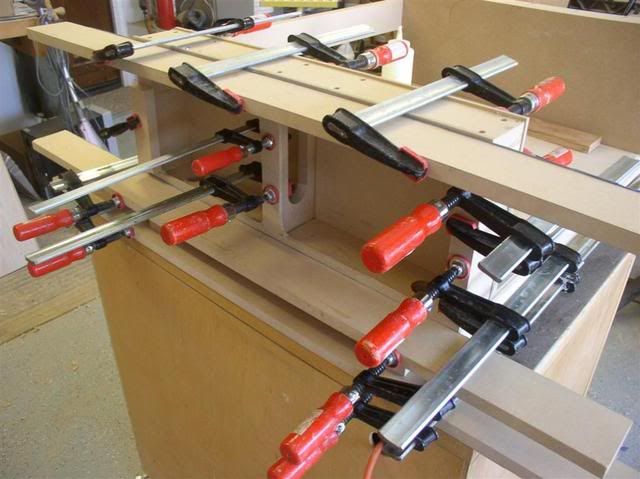
Tools: I’m fortunate to have a very nice table saw and a good chop saw, so dimensioning parts is fairly straightforward. Sharp chisels make quick work of inside corners. A good square is essential. Those cheap plastic drafting squares are good for checking alignment and a set of home-made cabinet construction squares help holding things while the glue dries. And you need a whole bunch of clamps. No nails or screws were used in this assembly. Glue is sufficient.
Time to build was two days, but most of that time is waiting for glue to dry. So, I did other tasks around the house in the mean time. Actual build time was probably less than 5 hours excluding paint.
I started by red-lining the plans to suit the material I had on hand. I had half a sheet or more of 3/4” MDF and several cut-offs of 1/4” material. I decided the bottom and top skin would be3/4” and the right, left inner and outer skins would be 1/4”. Most of the other parts as are according to plan. Since it was going to be left/right symmetric, the front and rear plates both have vertical portions that were 2.875” each side instead of the 1.5” dimension on the left side. This, of course changes the overall width for the bottom and top skins and the Y ribs. I eliminated the bottom plates on the left and right as redundant and made the left inner structure the same as the right. Pretty much every part is a somewhat different dimension. I decided I would use T-nuts and bolts as opposed to lag screws for the X rail attachment making the left/right top plate assemblies 1” thick.
On to construction…
Instead of cutting everything out at once, we will cut as needed since we are altering so much. Since my table saw is very repeatable, no issues with accuracy in doing this.
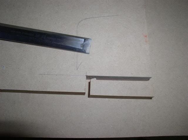
Torsion box: The top and bottom skins were cut and the top notched out on the table saw and finished up with a very sharp chisel. MDF pares easily with a sharp chisel. I do not recommend my method of cutting notches unless you are quite familiar with your table saw.
A little discussion about torsion boxes for a minute. The webs serve to transfer shear from the top to the bottom skin. It matters not how that happens. Within very liberal limits you can use anything you want for this grid including cardboard honeycomb, closed cell foam and the suggested ribs. Rib thickness can be pretty much anything as well. Also, note that the notches add nothing to strength as all the strength is in the glue. Modern glues are stronger than the wood after all. Thus, for this build, I eliminated the notches in the X-ribs and made the Y-ribs in little sections inserted between the x-ribs. This is easier to do since all the pieces are just rectangles. Notches are a pain to make and not necessary. If following the plans, just eliminate the notches in the X-ribs and Y-ribs. Glue in the X-ribs and then cut the Y-ribs to fit each individual location as your dimensions won’t be perfect. Easy.
Note that my ribs are shallower than normal due to the thick top/bottom skins. I guess you could just make the entire assembly taller too, I just didn’t see the need.
And a little glue discussion…Since MDF (and plywood) absorb a lot of moisture on the edges, I like to put a very thin layer of glue on all edges first. Then apply glue to the mating surface. Then go back and add little more glue to the edges. In the end, you still only want just enough glue to make sure when you put the parts together you get glue everywhere. A very minor amount of squeeze out is the goal. Clean up squeeze out as you go with a damp rag.
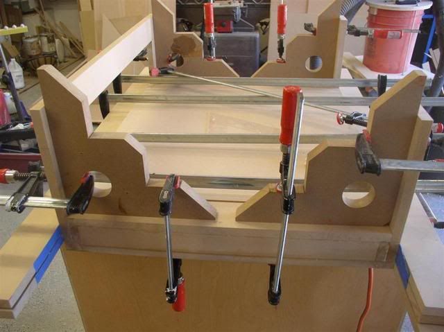
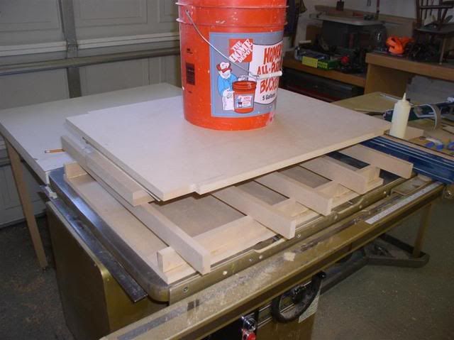
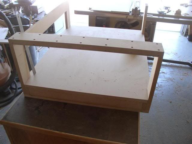
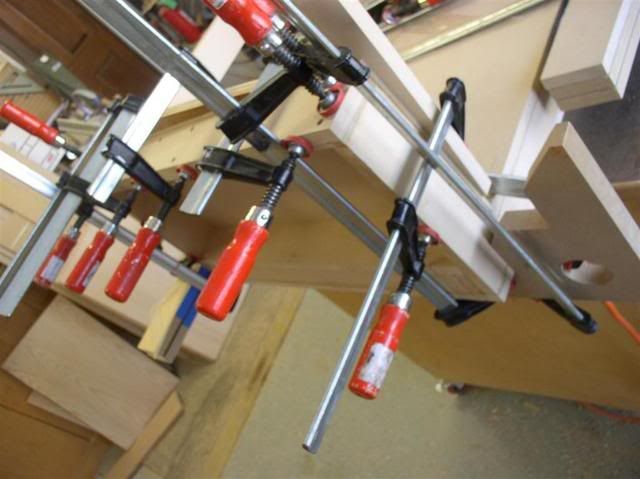
What flatter surface do you have in your shop than your table saw? Makes a great glue-up surface and will helps your torsion box come out flat. Note the incredibly expensive clamping method. 5 gallons of water in a plastic bucket and a few scraps of MDF to spread the load. This is the part that takes the most time. I glued in the outer Y ribs as one glue-up, then the outer X-ribs. Then worked the inner ribs in sections. 5 total glue-up operations and standard yellow glue needs to be clamped for about an hour to set-up enough to continue. Lots of wait time. Then the top skin was applied. Got to work fast so the glue doesn’t dry before you set the top on. You will also see a couple of strips of plywood in the structure. What can I say, I’m cheap and no one but me and you will ever know.
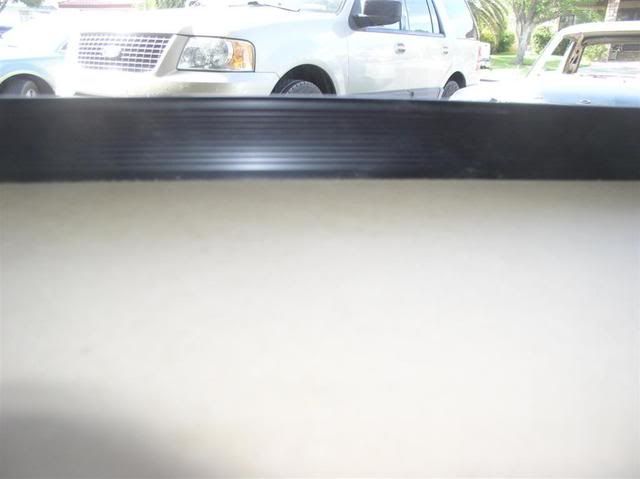
Is it flat? That straight edge is good to about 0.003”/foot. No light under it. Flat enough.
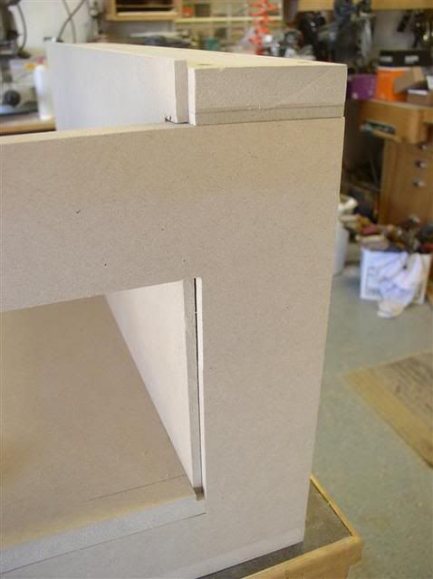
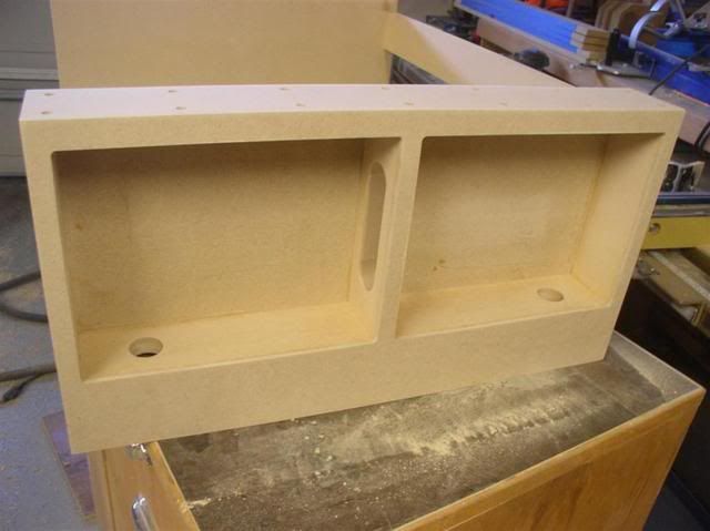
Since we are eliminating the bottom plates on the left/right we need to provision for transferring the mechanical bending loads from the sides into the bottom. We will do that by dadoing the inner side skins into the top skin. This is more structurally efficient than bonding the inner skins to the bottom plates anyway. I also made sure one of the X-ribs was directly under this location so that the load gets transferred into the rib as well. 1/4 x 1/4 grooves will serve this purpose. Forgot to take a picture of cutting the groove, but you can see the result in this picture. I cut the groove by shoving the entire torsion box through the table saw. You need to do this before anything else is attached to the torsion box, so plan ahead.
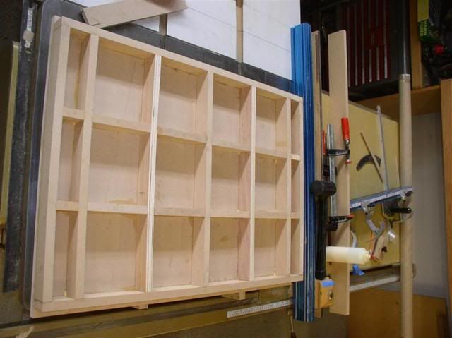
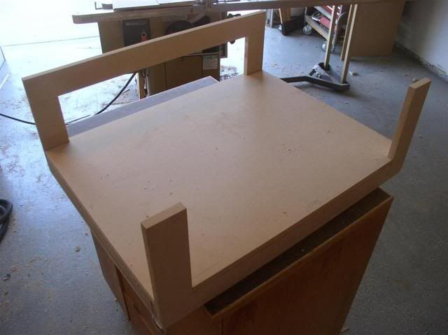
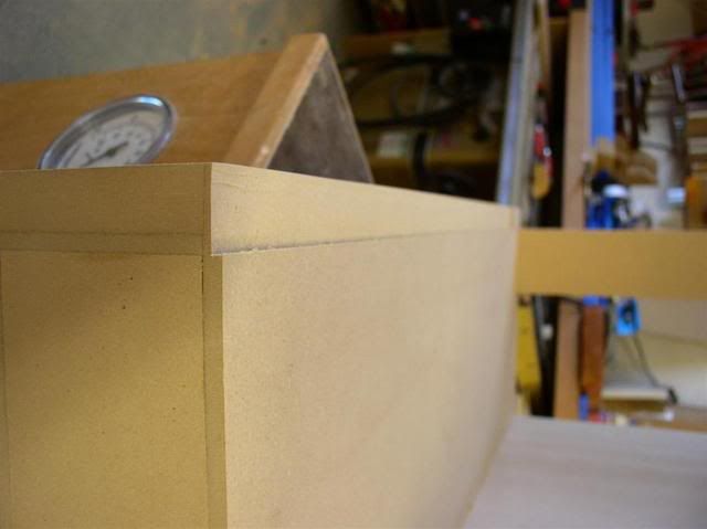
Front and rear plates are next. Not much special except to insure that they get glued on square. I used some assembly squares I had previously made. You need to make sure you cleaned up any glue squeeze out in the pockets of the torsion box where they fit or they won’t sit all the way down and leave a gap.
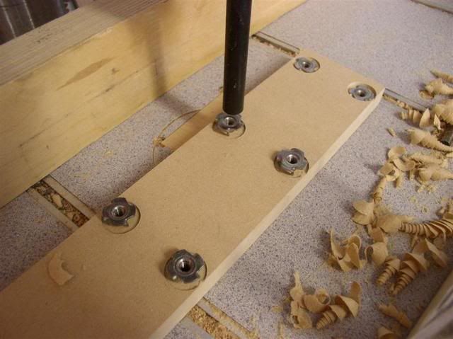
On to the left/right top plates: These are definitely different. I wanted to use machine screws instead of lags. I figured I would assemble/disassemble this multiple times and MDF and lags wouldn’t work well. T-nuts are the traditional choice for embedded threads, but they tend to get pushed out sometimes, so I laminated a ¼” board to the bottom of the plates after installing the t-nuts. I also did not cut out the stepper motor cut-out at this time as it would make the plate too flimsy to glue up. I’ll do that afterwards when I get my motor and make my metal parts.
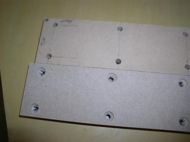
Lets discuss hole lay-out briefly first. Always layout holes from one end/edge of your part only, not from both ends. Also, layout each hole individually from the end to avoid accumulating errors. For instance, in this part, you have 7 holes spaced 3.75” apart. If you make an error of the width of a 0.5mm pencil lead (0.020”) between each of the 7 holes, you accumulate an error of 0.14” by the 7th hole. That would make parts not mate up. If you instead mark each hole individually from the same end, each hole could only be off 0.020. Measuring from the same end is necessary because you might have mis-cut your 24” length of the top plate and measuring some holes from one end and others from the far end would also introduce error you do not need or want. I chose to use the inside back corner as my measurement reference and will do the same for the metal parts that will attach.
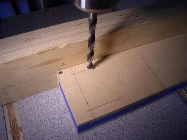
Holes were laid out on one part and the left/right were taped together for drilling. Double stick tape is hard to remove, so I just taped the sides together. I used a brad point bit to drill and its easy to set to long axis offset to the drill press fence by turning on the drill press and sliding the fence fore/aft will viewing the bit from the side. Then, you only need to worry about one dimension when drilling the line of holes. Note the pencil dot indicating the inboard back edge of the part where all the dimensions are referenced.
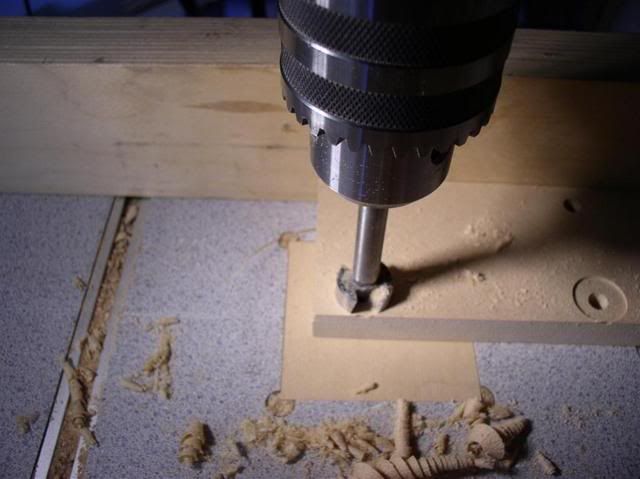
The parts were separated and the spot faces for the T-nuts were made with a forstner bit. Great accuracy is not needed here, just make sure the spot faces are deep enough.
I pressed in the T-nuts with a large drill bit inverted in the drill press head.
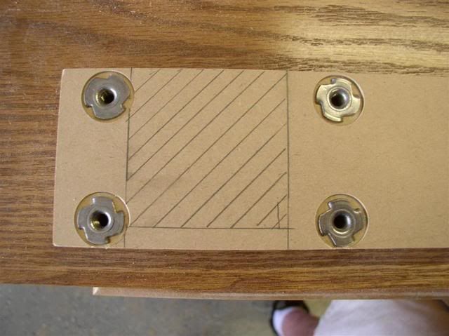
Note that the stepper motor cut-out will be extremely close to some t-nuts. I’ll have to be careful when I make this cut later. I’ll use a well worn router bit so I don’t care if I nick it.
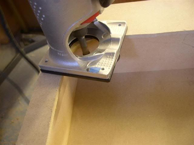
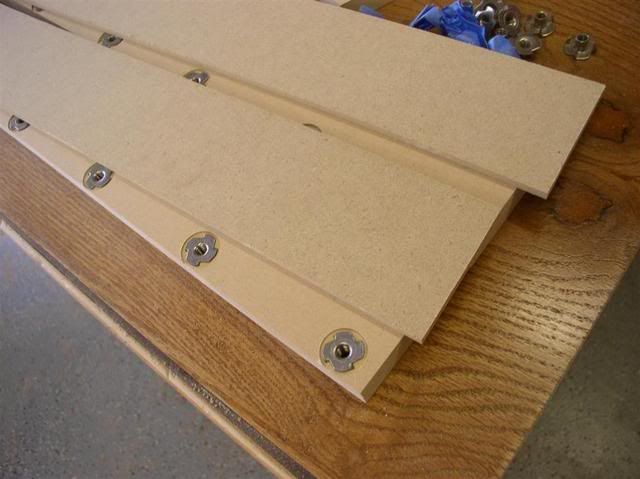
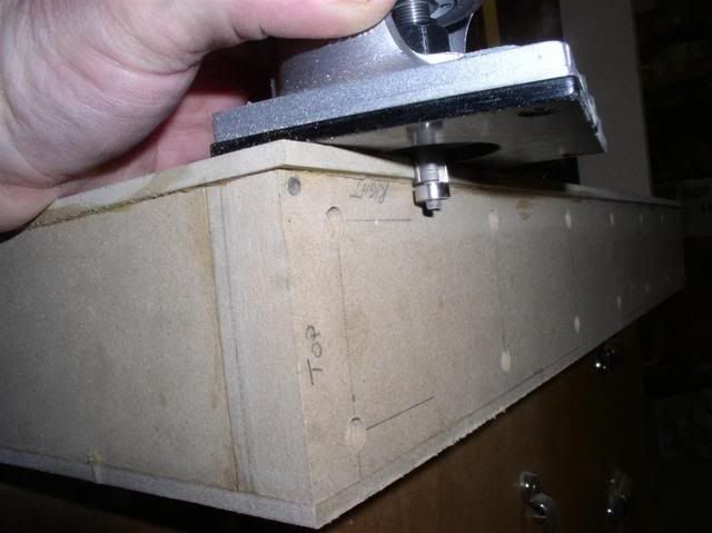
1/4” backers are cut a bit oversized and trimmed later on the router table to exact width using a bearing guided bit.
The end result. I drilled through the T-nuts from the front side and then drilled a relief hole on the back for the screw to poke through the backer.
Sorry for the long diatribe about the X-plates.
Let’s get back to building the basic structure now…
Left/right sides:
Since we eliminated the bottom plate and most of the guts, we stick build this one piece at a time instead of an assembly. Top plates first. Make sure the inside back corner is properly located since the part looks symmetric.
Inner skins were rabbetted to 1” wide leaving 1/8” in thickness. No need for the taper and I didn’t cut the wrenching relief. I’m going to attempt to not cut those, but if necessary, I can cut them later. Here is the rabbet post-glue up.
Inner skins were marked and notched for the rear plate and then glued-up. They were allowed to be a bit oversized and trimmed with a router and bottom bearing bit to flush. I also glued in the center supports at this time, but not shown in the picture. The center supports were built a little long and trimmed after glue-up to fit.
Outer skins were similar. I roughly cut out the two big holes with a jig saw and trimmed them up to the inner frame with a router and bottom bearing bit post-glue-up. I just left the radii in the corners for now. This panel was cut a bit wider and trimmed to fit after glue-up as well.
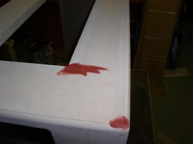
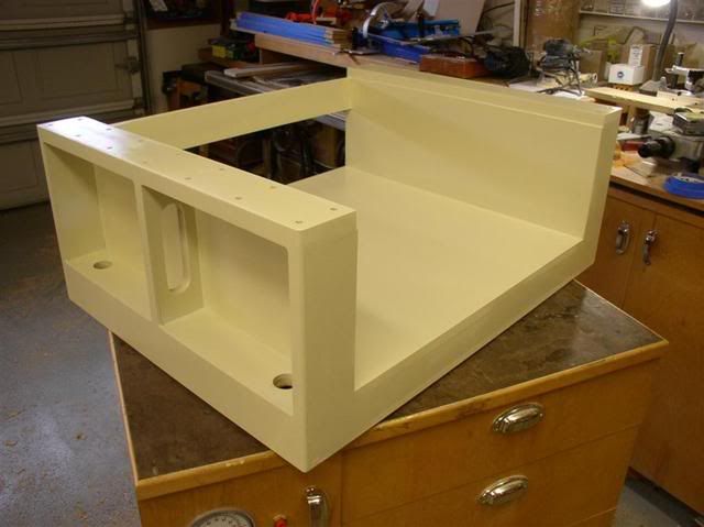
A little sanding and some automotive spot putty to fill the defects. I added a round over on the outside edges since they will get damaged if left square. I chose Rustoleum Almond as the color. Kind of industrial but not too dark and its not pure white to show all the dirt. I sprayed with an HVLP gun. I’m not completely happy with the finish and will likely add another coat after everything is built.
We will worry about the front flange and cover once we have a working machine. Doors will be done later as well.
Total cost out of pocket: $12.00 USD for paint. I like cheap.
Thread: Michael's Momus build
Results 1 to 20 of 27
-
06-08-2011, 05:57 PM #1
 Registered
- Join Date
- Apr 2011
- Posts
- 121
Michael's Momus build
-
06-08-2011, 06:37 PM #2
Registered
- Join Date
- May 2010
- Posts
- 118
Very nice!
-
06-08-2011, 10:53 PM #3
Registered
- Join Date
- Dec 2006
- Posts
- 202
Michael,
Fantastic write-up and photos. Very thoughtful modifications, and the craftsmanship looks top notch. As much as MDF gives me the heeby jeebies, this is going to be a beautiful machine. And for that cost I'd build one out of that in a heartbeat. I'm looking very forward to seeing more progress reports. And I like that blue anodized table saw fence. It perfectly matches your liberal use of blue painters tape.
-Bob
-
06-09-2011, 02:01 PM #4
Registered
- Join Date
- Sep 2010
- Posts
- 0
Well done Michael. Makes me a bit intimidated to post more pix of my build after seeing the excellent workmanship of your build. And all done in a portion of one day - I am at least 3 weeks into the base building process.
Dave
-
06-09-2011, 02:54 PM #5
Registered
- Join Date
- Apr 2011
- Posts
- 121
All - Thanks for the compliments.
Bob - MDF is a fine material as long as you work within its design constraints just like any material. I really want to make things out of carbon fiber, but thats expensive and slightly difficult. If I had an oven (and a pile of cash), I could do it.
Blue tape? Can't live without it. If I'm doing woodworking, I'll go through a roll a project. Much easier than scraping glue and getting rid of layout lines. Wait until I do the metal work. More blue tape there for sure.
The Table saw fence is a 4 foot Kreg Jig extension. The plywood fence face on my Powermatic 66 was a bit wavy so I ditched it for the extrusion. I wouldn't have cared if it were pink. Its a very nice alternative for a replacement fence.
Dave - Two days to build. 5 hours of clock time. Mostly waiting for glue to dry. Admittedly, I might have some better woodworking tools than many. If you have any question about methods of work, please ask. If I were working on a sawhorse in the backyard with a circular saw and a straight edge, it would go very much slower. And Family issues that many folks have are a non-issue.
-
06-09-2011, 02:59 PM #6
Registered
- Join Date
- Apr 2011
- Posts
- 121
Dave,
I went back and looked at your build thread. You are way ahead of me on the metal work and your woodwork is fine. Nothing to feel bad about there.
-
06-09-2011, 07:25 PM #7
Registered
- Join Date
- Apr 2011
- Posts
- 0
Wow Mike,
Just when I thought you couldn't procrastinate starting your build any longer, you didn't!
Looks good!
I work the opposite of you thought, I build per the plans then modify after. Not the cheapest way to go but it lets me see where I need adjustments to fit my needs. Build the machine, make the changes, build the new machine with changes implemented.
I made one change to mine this weekend and that was the left X-rail. The cold rolled steel bar had rough edges that i filed smooth but still wasnt perfect because I would have had to remove a lot more to get a nice flat surface. I picked up a piece of 6061 bar at 1/4" thick to replace it since aluminum bar is pretty uniform in width and the added thickness let my bearings contact the surface completely. Now I get a nice smooth motion on X and the change only took 30 minutes with drilling and tapping. i am at the point I can start the "all metal" build of the machine. Well all metal except for the ribs of the torsion box which will most likely be delrin.
Lookin forward to see more progress!
billj
-
06-09-2011, 08:04 PM #8
Registered
- Join Date
- Sep 2010
- Posts
- 0
Thanks Michael for the compliment. I intended to fix up some rough spots around the hole I cut for the motor cables last night so that I could post a few more photos but got side tracked. Took advantage of my son being available to help with a "dry fit" of the metal machine and found out I need to move the left end out to sit on the left rails. Hopefully that is done and tonight I will get on with what I was planning to do last night.
Dave
-
06-09-2011, 08:14 PM #9
Registered
- Join Date
- Apr 2011
- Posts
- 121
I actually built the base two weeks ago. I just wanted to write one complete post for the whole frame build and needed the time to write it. I don't like doing little updates. I llike reading them, just don't like writing them.
To a degree, I did "build to print" first. I made a sketchup CAD model of the entire machine and then modified it in the computer to suit my needs and wants. It is not easy to look at flat drawings and make the same assessment.
There are certain things I knew I would change as I built the initial CAD model, but I went and built it that way anyway.
By the way, I have my electronics suit ready and my metal is delivered, but you won't see much about them until I have a big thing to present. I like big.
I still need some things like pulleys, belting, some wire, and to decide on the spindle mount.
-
07-21-2011, 03:09 PM #10
Registered
- Join Date
- May 2010
- Posts
- 118
Hi Michael,
Any progress? I'm anxiously waiting to see the rest of your build!
Randy
-
07-27-2011, 05:12 PM #11
Registered
- Join Date
- Apr 2011
- Posts
- 0
I was wondering same. I understand it is summer and you got to take the kids to Disneyland and all but nothing in almost 2 months? Originally Posted by groswald

Everything OK, Mike?
-
09-06-2011, 04:00 AM #12
Registered
- Join Date
- Apr 2011
- Posts
- 121
Nice to know I'm missed. I promise I haven't been seeing another CNC forum. Originally Posted by bjesson

My apologies to all for not staying in touch. Life has been busy. Kids are old enough to take their kid to Disneyland so that is no excuse.
Work and family are more important than hobbies, so they will always come first.
I see we have a few new faces to get to know and a few threads I need to read up on.
What is up with my build? I've had a big long weekend to work on things.
I have all the metal parts assembled excepting the wire booms (haven't figured out what I want there yet.) I'll detail all my trials and troubles about the in one long post like the wood working. Won't be as long as I didn't take nearly the same amount of pictures. I have one or two modifications that are worth pursuing for some folks.
I have tested my electronics on the bench just to make sure the parts were not DOA. Seems to work fine on the bench. I'll start wiring next weekend.
I need to figure out my router mount next. I have no material ordered for that yet.
I don't even have a teaser pic ready to post.
Anyway, progress has been made.
-
09-11-2011, 09:19 PM #13
Registered
- Join Date
- Apr 2011
- Posts
- 121
First Motion
I know I owe some more build pictures, but I just had to post.
No cable management, no limit switches, no real motor tuning. Just barely have the electronics working. I still have some adjustment and tuning of the mechanical parts to do as well.
[ame=http://www.youtube.com/watch?v=g7ldl-1aGyo]Michael's Momus CNC first motion - YouTube[/ame]
-
09-11-2011, 09:26 PM #14
Registered
- Join Date
- Jan 2010
- Posts
- 0
That looks fantastic, Michael! I'm still stalled on my build for the moment, so it's always great to see others making good progress. Keeps my hopes for the future alive.
Congratulations!
-
09-13-2011, 05:36 AM #15
Registered
- Join Date
- Apr 2011
- Posts
- 121
I still need to post the metal part of the build, but the electronics are easier, so we will do that first.
Again, I have to be different and I have to be cheap.
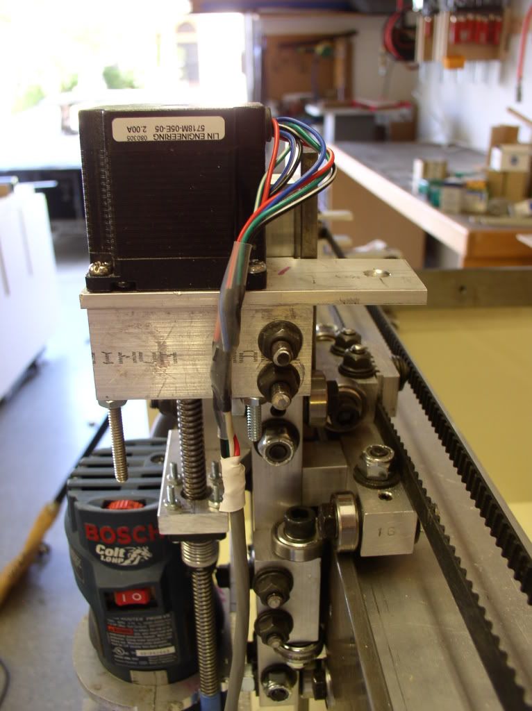
Steppers: LIN ENGINEERING 5718M 2A Unipolar motors for all axes. Small compared to some, but they only cost $10 each. NEMA 23 sized, so they fit just fine. The ones I ordered from E-Bay were 8 wire, thus they could be wired unipolar, bi-polar parallel or bi-polar serial. One reason I picked them (Price being primary) was that I could use any stepper controller I wanted. They are listed at 130 in-oz unipolar, 294 in-oz bipolar.
5718 High Torque Stepper Motor |NEMA 23
I bought them from e-bay seller “cncjunkie”. Note that he sells them with and without the attached gear. Get them without as it’s hard to remove and it’s not the right size. I bought them with the gears hoping they were correct. It took two hours to remove three gears. They were Loctited to the shaft.
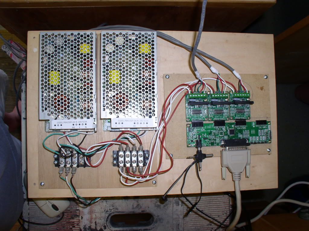
Electronics suite: Probably not one you have seen before. SOC Robotics MK4 Break-out-board and 4 MK160 bi-polar drivers. The drivers are 3.5 amp maximum. Why? Again, cost (as usual) and perceived quality). The drivers are the usual TB6560 chips, but these are a completely different design. I e-mailed the company in Canada and he convinced me that he know what he is doing. Time will tell, huh? $65 bucks.
SOC Robotics Smart Embedded Products
I bought them from E-bay seller “modularcnc” who is actually SOC-robotics themselves. Current price looks to be $75.
Power supply(s): Again, cheap as I can be, I needed 24 volt power supplies and about 10 amps or so. I didn’t find exactly that, but I did find 6.5 amp supplies for $15, so I bought two. I used one for the X-axis and one for the Y and Z. Why so cheap? They used a proprietary power connector. No problem, just soldered on some pigtails.
I got my stepper motor wire and pulleys from Hubbard CNC just like most folks do.
So, what does it look like? The power supply board will fit in the forward right bay and the CNC controller will fit in the aft right bay next to the X-axis stepper. For now, I just put both boards on a larger board to keep them off the floor. I’m not happy with the mounting hole layout on either board, so I’m thinking I’ll wait until I can CNC some better ones.
-
09-14-2011, 06:33 AM #16
Gold Member
- Join Date
- Apr 2009
- Posts
- 5516
Great work so far.... nice... Originally Posted by Michael In Cali
-
09-26-2011, 03:54 AM #17
Registered
- Join Date
- Apr 2011
- Posts
- 121
Metal parts build
The metal part of the build: This kicked my butt far more than it should have. Mostly my fault though and I’ll tell you what I did wrong along the way. Also, there are not many in-process pictures as I somehow managed to not store them someplace I could find them. Sorry about that. That also means Bob won’t get to see too much more blue tape.
To recap, this is not a standard build as I made the left and right sides of the machine the same height and width with the possibility of using the new left hand bays for more entertaining guts. I also made a few enhancements and will note so when they come up.
Safety:
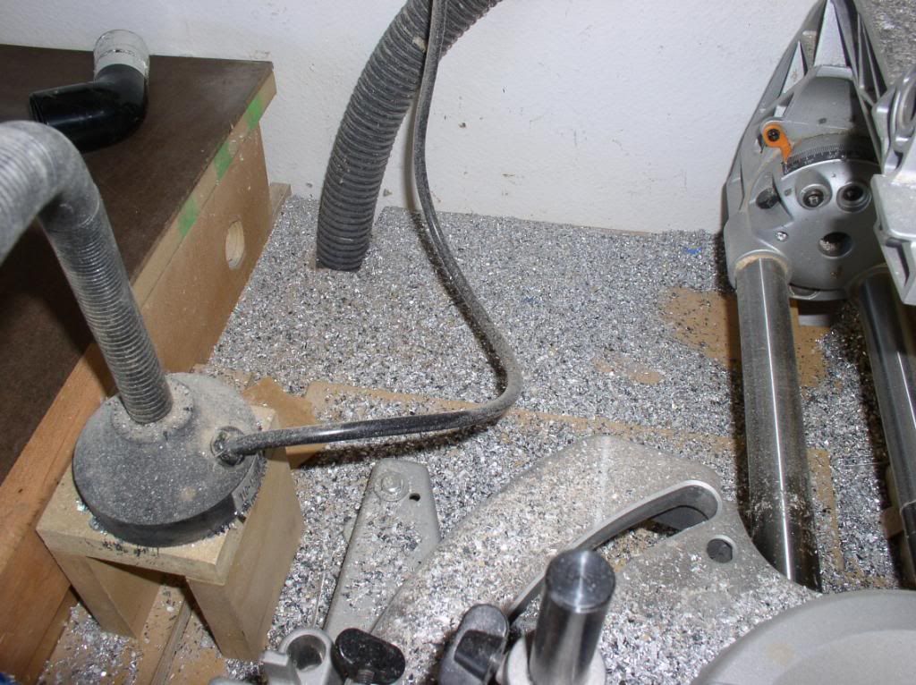
Let’s start with a little safety info. I’m using a common woodworking sliding compound miter saw and it’s not supposed to be used for metal working. So, I took off some of the plastic parts and then put down ¼” hardboard on the fence and table. I knew I’d probably kill the blade, but it was due for replacement anyway. I’d suggest buying a cheap blade if you go this route. I cut the aluminum on the miter saw just fine. I also cut a few steel parts. I do not recommend it. The blade is missing a few teeth and is completely dull now. Remove any dust bag on the miter saw and clean up all saw dust before proceeding. I also did a few cuts on the table saw. I completely vacuumed all woodworking dust up before using it. When you’re done with all the parts, you will have this metal mess to clean up.
Part layout: Always measure starting from the same place on the part. Don’t measure some holes from one end, some from the other. If the part length is not dead-on, you will have errors you may need to fix later. I believe Bob is going to be more consistent when he does the next revision of the drawings. Also, its generally better to mark each hole using the end of the part than to lay out from hole-to-hole. Tiny errors on each measurement add up and the last hole can be off a lot. So, do the math and re-mark the drawing before laying out the part.
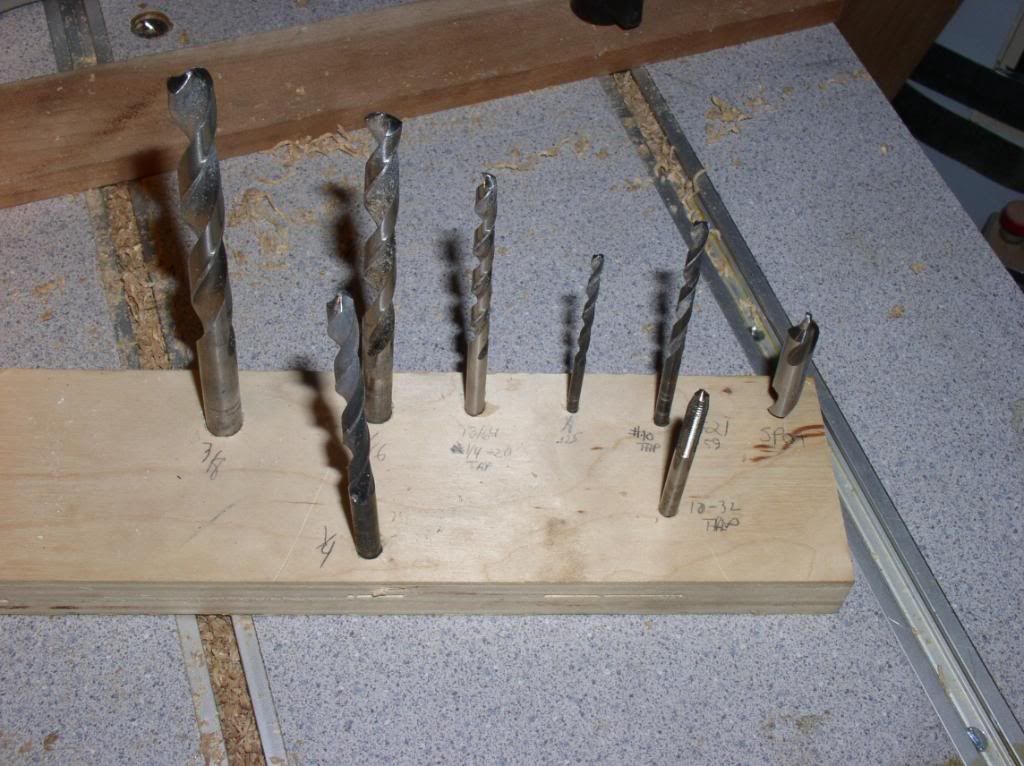
Organization: At the drill press (or portable drill if that’s all you got), you will be switching bits frequently. I took a scrap of wood and laid out my bits and their use so I’d not lose them.
I chose to cut each part or pair of parts individually instead of doing all one operation and then going on to the next one. I did this for a few reasons. Firstly, I wanted to get one or two finished to make sure I had the process down before ruining a lot of metal. Secondly, I have a bit of carpel tunnel syndrome and tendonitis and tennis elbow and the repetitive operations start to hurt after a while. Thirdly, I wanted to build up the machine as I went. To the third reason, I chose to start with the x-axis parts first, then the y-axis and then the z-axis. I left the drive components and various bracketry to the end as they weren’t needed to see the cool parts move.
X-axis:
X rail plates. Since the left and right hand x-rail plates are now mirror image, they both look like part 37 except one doesn’t get the motor holes. I also left out the front pulley attach holes and will explain why later. These parts are taped together and laid out at one time and processed as much as possible before separating and doing the motor holes. If your stepper motor has a raised face that needs to fit in the 1.5” hole, make sure it fits by filing and sanding the hole prior to laying out the 4 attachment bolt holes. Also, you might consider match drilling those 4 holes using the stepper motor itself for accurate alignment. Measuring 0.928 ain’t easy. I have a set of transfer punches so it was an easy matter to put the motor in place, center punch the 4 holes and then go back to the drill press and drill them.
For the x rail angles, again, I made two part 34 and just didn’t cut the motor holes.
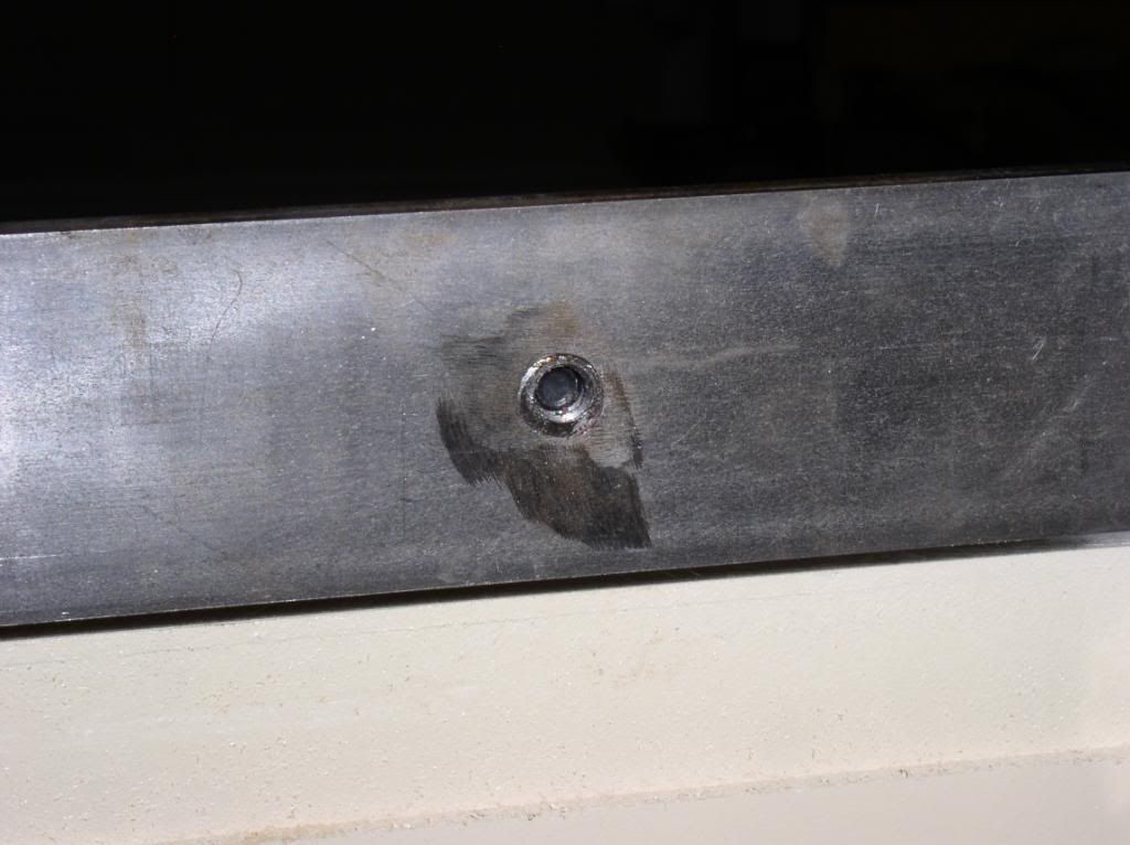
Ditto the X rails themselves. Same on both sides using part 33. This is my first real screw-up. I drilled these to a .3125 clearance hole instead of a tapped ¼-20. No problem, right. I’ll just get some ¼” all thread, cut it into lots of little buttons, plug the holes, loctiting in the plugs then redrill. It didn’t work all that well. I had an extra length of steel, so the right hand rail got re-made. I’m still using the plugged left hand rail and since its working fine, it will probably stay that way. But, it was a hassle not worth doing. When I went to tap the plugs, they would spin in the holes even though they were loctited in.
Here is a pic of the repaired holes.
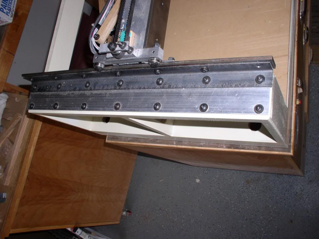
And the finished left rail.
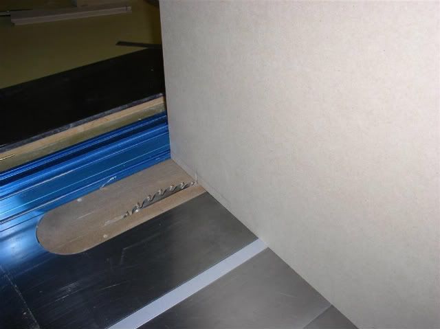
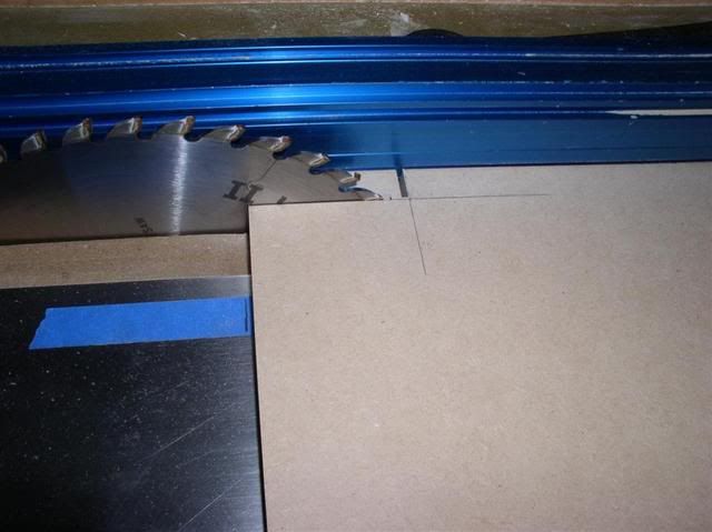
Y-axis gantry: Invest in a step drill that electricians use for drilling into metal boxes and use that to cut the big holes in the gantry tube. I chose to cut the notches on my table saw with the work piece held vertical once the holes were drilled. Not everyone’s cup of tea, but it works for me.
For all the 0.75 x 0.75 parts, the process is pretty much the same. Mark -drill-mark-drill-mark-drill until your head hurts. I use a fence on the drill press table set to a 3/8 center line and only mark for the length on the part. At some point, you will screw up and drill an off-set hole on center line. And you will yell at yourself. Oh well! You will also drill set-screw holes on the wrong side. No worries, just drill completely through and tap the side you like. Heck, tap all the way through if you like. No harm done. I elected to not make the counter bores except for parts larger than 0.75 thick. It works fine. For the thicker parts, you need the counter bore because your tap is likely not long enough.
Y motor mounts. You can skip cutting the notch. It adds nothing but making the part look pretty. Just make both 10-32 holes the same. If your motors have a raised face on them, you need to add some relief in the top face of the mounts or space your motor up on some washers.
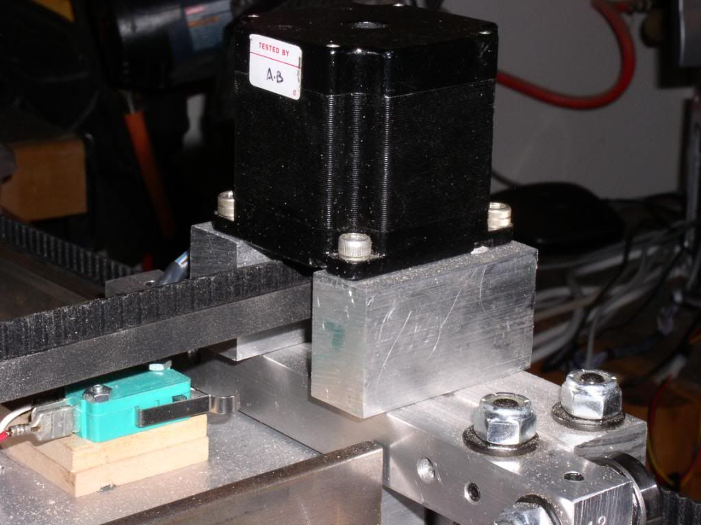
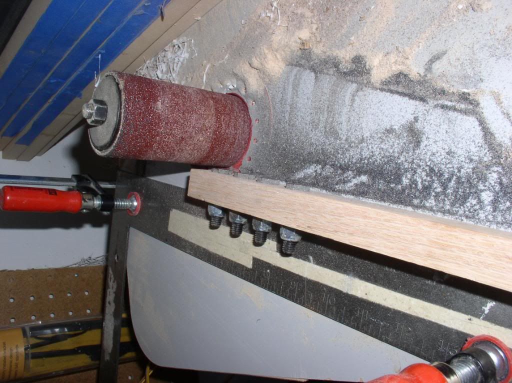
Here is where you need those fasteners with the heads ground down. I just bolted them through a scrap of wood and sanded them down with my drum sander. The fence you see in the pic was just bumped a bit closer to the drum with each pass. Quick and consistent.
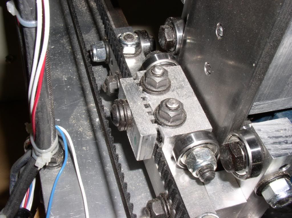
Not much else to say, the axis goes together fairly quickly once all the parts are done. I’ll talk about the belt attachment later. There is one issue you might want to fix on part 8. Go ahead and assemble and adjust. The x-axis can be attached later. You don’t need to slide it on from the end.
Carriage assembly:
More of the same. I screwed up and drilled a through hole instead of a #10 tapped holes for one of the set screws in a bearing block (part 15). Fortunately, only once. I was able to Loctite in a piece of all-thread and redrill successfully here. Plenty of surface area for the Loctite unlike the x-rails.
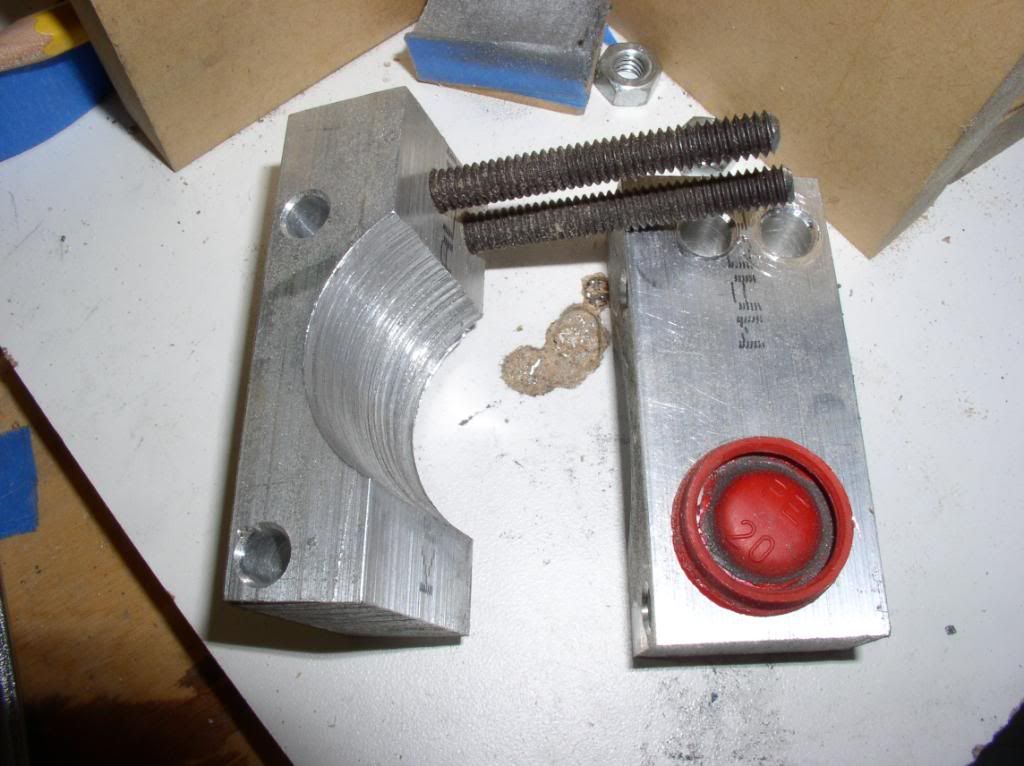
The only thing difficult here is the z motor mounts. For these, you need to cut the 0.625 radius and it seems difficult. But its not with a little trick. Again, skip cutting the diagonal on these parts. It’s unnecessary. Go ahead and drill the 0.3125 holes in part 20 and the mating ¼-20 holes in part 21.
Create a sandwich with some scrap plywood or mdf as a spacer. The spacer needs to be 0.75”. Plywood is a bit undersized, so some masking tape can be used as a shim to get the thickness right. Bolt your part 20, your spacer, and then part 21 together making sure your motor mount holes are outboard if you already drilled them. Use a c-clamp opposite the bolt holes or the parts will want to spread apart. Then, with the center marked and pre-drilled, use a bi-metal hole saw to cut all the way through. You can use a bit larger hole saw and it’s not critical. I happen to have a 1.5” hole saw, so my radius was 0.75. Also, take the plastic pads off your c-clamp. They melt and stick.
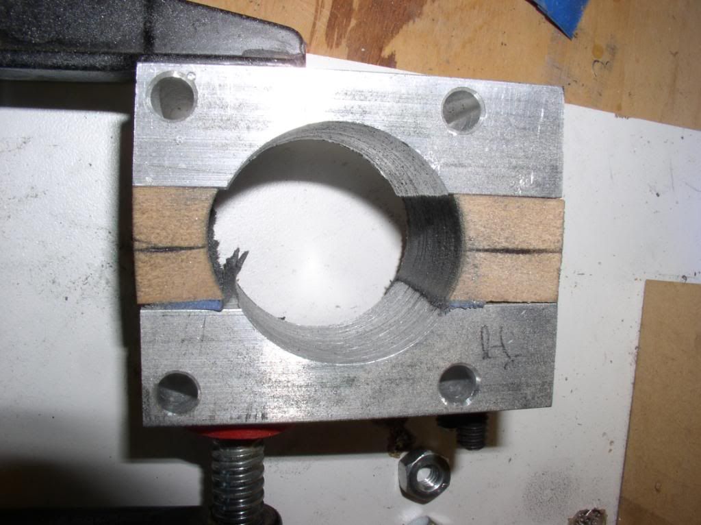
Assembly of the carriage is straightforward. Put it all together on the bench first. Then, remove the lower part 16 with whatever happens to be attached to it. Place the carriage on the gantry and re-install part 16. No need to remove the gantry.
The Z-axis is straight forward. If using one of the available Bosch mounts, account for the different lower two hole spacing before assembly or you going to be taking it apart again. But it’s not difficult if you do.
Odds and ends:
Timing belts.
Y-axis. You can use a 250 tooth (50 inch) continuous belt for the y-axis without any modifications. It’s a perfect fit. No need to worry about installing a spliced belt. The continuous belts at McMaster-Carr can be had in kevlar belting which is a bit less stretchy than the suggested glass belted.
X-axis. You can use a 210 tooth (42 inch) continuous belt for the X-axis with a little modification. It works nice and I’m real happy with this deviation from the plans. This is why I didn’t drill the forward pulley holes in the x-axis motor plate. I’ll have to detail the exact part dimensions for this in another post, but basically, you create a sliding pulley mount. You install the belt with the plate in its most aft position and then use the jack screw to tension the belt. It works real slick. Just don’t over tighten the belt.
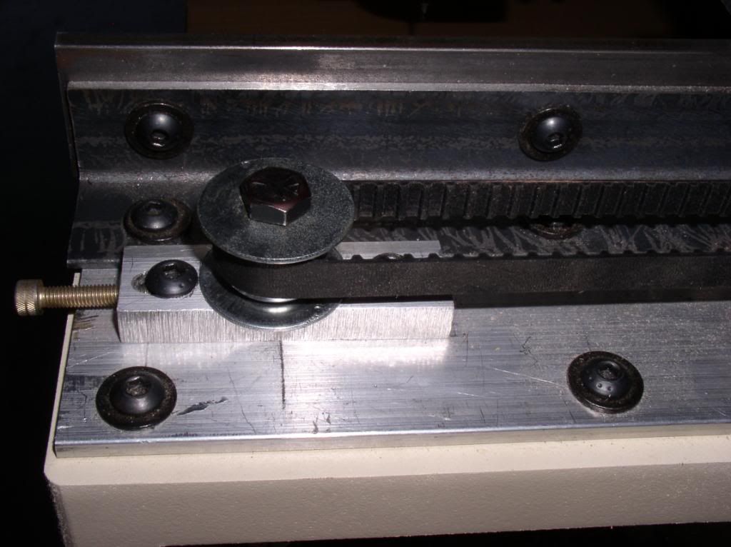
Timing belt clamps.
Firstly, for part 8, the x-belt plate, the two lower holes are better off being tapped ¼-20. Not 0.3125 thru as defined in the drawing. Its too hard to get the nuts on the bolts as designed. It would be a very easy change.
If you have a table saw and don’t mind scaring yourself a bit, you can cut the grooves using a thin kerf carbide blade. You start at one edge of the part and then just move the fence right exactly 0.2” and make another pass until you get all the grooves cut. I clamped a digital caliper to the tablesaw fence to guarantee correct placement. Use a good push block and a second hold down, eye protection and you should probably wear a cup too.

Cable arms:
I used ¾ x ¾ hardwood. Much quicker and easier. If you counter bore the ends with a ½” forstner bit, you can eliminate the custom washers. I'll deal with the wiring and limit switches in a separate post.
-
09-29-2011, 03:27 AM #18
Registered
- Join Date
- Dec 2006
- Posts
- 202
Wow, fantastic post! All of the modifications you've made are really well thought out and implemented. I particularly like that jack screw tensioner on the X belt. But I do think I'll skip the method you used to cut the grooves in the belt clamp. I'm pretty comfortable around my table saw, but that would be pushing the boundary a bit too much for me.
Thanks for figuring out how long of a continuous belt will work on the X and Y. I've been meaning to do that for a while now. I'm really kicking myself now that you point out that both sizes are nice round figures. I'll have to include this info in the next plan revision. But why couldn't you have posted this a couple of weeks ago? I just got an order from McMaster Carr a few days ago and this definitely would have been included, had I known. I've been wanting to test out some different belt/cord materials for a while now.
I do see a little bit of blue painter's tape in a few of those photos. Although you make up for any shortage of tape in photos by showing us your nice baby blue limit switches.
One last thing- those black button head screws and flange nuts look sweet.
-Bob
-
09-29-2011, 03:50 AM #19
Registered
- Join Date
- Apr 2011
- Posts
- 121
Thanks for the kind words. You will have to do some math on the exact position of the tensioner. I just laid it out and center punched the loose end of the slottted holes. The nice thing is it can be done post-assembly and you don't really need to know the location. Eyeball works fine.
The limit switches are lime green. You need a new monitor (or new eyes)
Yes, I like the black oxide fasteners. Not too much more money but the 5/16 locknuts I thought were ridiculously expensive, so I passed. I really should take it apart and polish the aluminum and paint the steel black.
And somewhere, somehow, I'll find more uses for blue tape.
-
10-06-2011, 02:14 AM #20
Registered
- Join Date
- Mar 2011
- Posts
- 144
Do you have any drawing of your router clamp ? or can you take better picture ?

 Reply With Quote

Similar Threads
-
Welcome Momus Builders
By kemper45 in forum Momus Design CNC plansReplies: 5Last Post: 02-01-2012, 07:44 PM -
Momus Design CNC Plans
By iplay1515 in forum DIY CNC Router Table MachinesReplies: 136Last Post: 09-27-2011, 05:46 PM -
Momus Design + AC Servos
By vigen20 in forum Momus Design CNC plansReplies: 12Last Post: 06-09-2011, 10:49 PM -
Momus Logo?
By groswald in forum Momus Design CNC plansReplies: 4Last Post: 05-20-2011, 03:29 PM -
Some questions on Momus CNC Design
By Michael In Cali in forum Momus Design CNC plansReplies: 21Last Post: 05-06-2011, 09:25 PM
