


Hi All
I have posted a set of AutoCAD DWG drawings using 3d solids. The main drawing is Epoxy Concrete 01 Main.
If you download only the main file alone you will see very little You need the linked files for Autocad to display the image.
Just put them all in one directory so Autocad can find them when you open the main file.
You can find the files here:
Free File Hosting Made Simple - MediaFire
There are only 2 layers to check;
One for the way covers
One for Dimensions
Both are turned off
I have a granite surface plate 630 MM x100MM. My plan is to cast all the parts for this mill using the surface plate to generate flat surfaces.
The top of the base (It will be made upside down)
The face of the columns
The face if the bridge
The face of the spindle carriage (using ground blocks)
I am still undecided on the overall height. It can be increased.
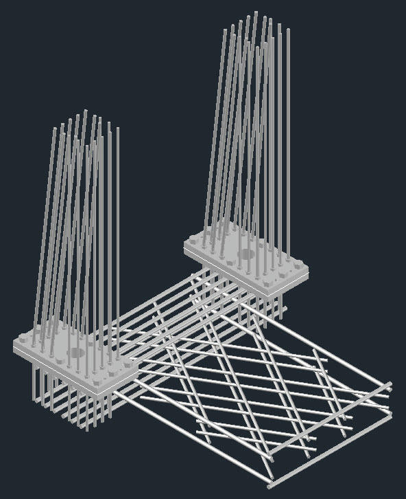
The 190MM High base design has a lattice grid created by polystyrene blocks. It is planned to place 12mm deformed steel bar in each diagonal lattice 40 mm from the top and 25mm from the bottom for reinforcement. The outer edge of the base is reinforced with 12mm deformed bar bent into a rectangle tied and overlapped 40mm from the top and 25mm from the bottom edge.
The columns and bridge beam to be similarly reinforced
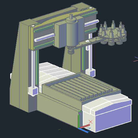
As the plans show the machine comprises a number of frame parts.
The main parts to be made from Polymer concrete are:
Base
Two columns
Gantry brace
These parts are to be made separately, when completed they will be joined as one.
This will allow final alignment of the columns to the bed; ideally this should be done with removable fixings for those with difficult access issues, and limited means of transport.
I am considering cast in studding through metal plates with jack screws for adjustment (The joint to be grouted with the Epoxy from my other thread)
Moving Bridge beam
Reinforced as above.
The Moving carriage that holds the spindle to the bridge beam
This could be made from steel or polymer concrete, I do not know if the thinner sections will be strong enough with polymer. (The spindle is 110mm Diameter) 40 taper socket
All the linear guide rails are size 25
25mm Ball screws for all axes
Next step is to analyze the structure I guess I will have to come to terms with finite analysis software.
The control system will be Mach 3 using servos.
Cheers
John McNamara
http://www.mediafire.com/imgbnc.php/...bfa209216g.jpg

Results 1 to 11 of 11
-
04-25-2011, 09:53 AM #1
 Junior Member
- Join Date
- May 2007
- Posts
- 68
Epoxy concrete CNC mill 500 X 500 X 320h work area concept drawings
-
04-26-2011, 11:10 AM #2
Registered
- Join Date
- Oct 2005
- Posts
- 2392
I like it. It's attractive and the geometry is pretty good.
It's main weakness is trapezoidal, you might consider thickening the uprights (outward) which will also make them easier to pour.
Unless weight or cost is an issue I would also thicken up the top beam to match the size of the uprights. It will be easier to make the mold, easier to pour and more rigid.
-
04-26-2011, 01:33 PM #3
Junior Member
- Join Date
- May 2007
- Posts
- 68
New version 26_04_2011
Hi All
Thank you RomanLini Glad you like it, it’s very early in the design stage.
To be useful it needs and an automatic tool changer.
The question is how automatic? Apart from picking tools from a magazine and placing them in the tool holder, I want to be able to index them. That means the spindle Drive will need an encoder. With a zero point. The locating lugs on the spindle are not an accurate fit with the locating slots on the tool holder. And the tool holder itself has two slots 180 degrees apart. OK by orienting the tools in the magazine and picking them without rotating them that issue can be solved. Or is there better method? Maybe a sensor; that still leaves the angular misalignment due to the loose fitting lugs to be addressed?
With an ATC we already have 4 axis of control. A fifth axis would be very useful; Its the complexity (And Size) of the angular head that worries me. How do you get at least 2 (3 would be better) horsepower, a spindle and an angular drive, into a compact unit?
I would appreciate feedback from CNCZ members on this.
I posted an updated file set.
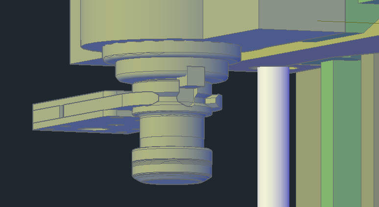
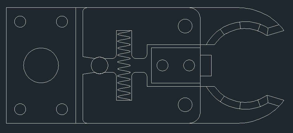
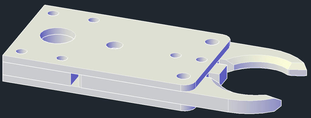
It includes the first draft of an ATC picking arm.
Inside the Zip file you will also find a folder with different gripper arm images and a specification for BT40 (From Iscar) I hope it is right
This time I zipped it so that it is easy and smaller to download as a unit (2.5MB)
You can find the file here:
http://www.mediafire.com/file/wdqywd...26_04_2011.zip
Cheers
John
Re Autocad:
Having started with AutoCad from its early beginnings it is a natural choice for me. Am I making the wrong assumption that most members can open the files? If so
Autodesk supply a free viewer here:
DWG TrueView - Stand-Alone DWG Viewer & DWG Converter - Autodesk
Tool changer images below
-
04-27-2011, 10:00 AM #4
Junior Member
- Join Date
- May 2007
- Posts
- 68
Tool Magazine
Hi All
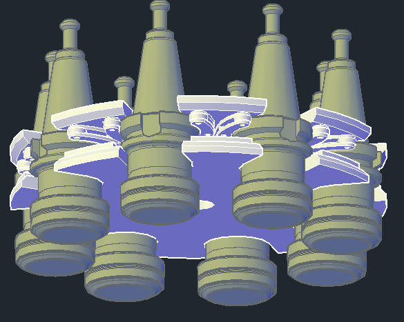
A quick Update
First draft of a tool magazine, I am very happy with the design.
Not so happy with the way it is accessed by the gripper…A lot more work needed there.
Note the small pin on the gripper. It will be used to lock the gripper to avoid dropping a tool.
Cheers
John
I posted the updated file set here :
http://www.mediafire.com/file/e8c61p...27_04_2010.zip

-
04-27-2011, 12:43 PM #5
Registered
- Join Date
- Mar 2004
- Posts
- 1306
I like that moving table design, and have been collecting parts (ballscrews and linear rails) to do a similar but smaller mill with 200x200x200mm envelope.
I don't have Autocad ( at least not from this millenium could you please post an image of your base without the guards installed?
I see a lot of vertical surfaces, are you intending to add draft for moulding, or just use a single use distructable mould?
What is your plan for guarding the Z and Y axis?
How do you plan to integrate the motors?Regards,
Mark
-
04-27-2011, 04:39 PM #6
Junior Member
- Join Date
- May 2007
- Posts
- 68
The devil is in the detail
Hi SMP
As I mentioned in the first posts my plan is to use a granite surface plate to cast the base, upside down with the top surface generated against the precision flat surface.
The columns need a flat surface on the face for the rails so they will be cast face down.
The same applies to the smaller parts. The plan is; wherever possible use the surface plat to generate true planes. The Granite is accurate to .0002 over a foot.
The granite will need to be protected from the epoxy so it will be covered with drafting polyester. I plan to print it with an accurate outline for the formwork that will be placed on top and to mark the position of metal inserts for the rail mounting screws. All formwork joints and the join with the polyester covering the granite surface plate will need to have a carefully filleted bead of silicone applied to stop leaking epoxy.
I also plan to fill slowly in layers allowing each layer to flash off before applying the next hopefully to avoid exothermic heat build up.
Will threaded inserts work for the rails? The screw holes on rail are a tight fit on the mounting bolts…and we need cam adjusters too. If there is any error it would be difficult to recover from it. So the current plan is to use simple mild steel cylinders turned flat on the end and white glued down on the marks on the drafting film, before casting. They can be marked and drilled later.
I plan to use a gel coat so when that sets the inserts should be stable enough to take the filling of the concrete mix.
OK so what of the connections?
I am of two minds?? One option would be to create lugs and holes and after wedging everything into alignment use epoxy grout to fuse the frame together.
Alternately
In the following order: (For each column joint)
Drill 2 pieces of 1.5 inch thick Mild Steel for the bolt pattern required.
Tap for Jack screws that will assist in aligning the machine, Ideally not required but just in case. If used the gap would have to be grouted.
Weld deformed bar dowels to the back of the plates to be cast in.
Machine the face of each pair to create a true plane and pick up and welding distortion.
My preference is the second option… Setting two columns and the bridge beam for a one piece pour, to a true 90 degrees would require elaborate and extremely costly formwork. I will be happy with adjusting and grouting.
As for your other questions:
None of the forms will have draft. They will be screwed together for removal but I doubt they could be reused.
I plan to use bellows to guard the other axis.
The electrics are not yet on the drawing board.
The table drive will be fitted within the box the way covers slide over at the back.
The table actually extends past the base 78mm front and back. If you check the position of the runners they are set back from the edge of the table, they sit at the edge of the T slots. (It would be possible to move them a little further in gaining more table travel)
The 2 column motors will be mounted on top of the columns, driven as a synchronized pair. Alternately they could be in the base of the machine, yet to be designed in steel. That would be neater
The bridge axis drive will need to be mounted on the bridge.
It will have to do battle with the tool magazine for space.
Cheers
John
-
04-27-2011, 07:15 PM #7
Registered
- Join Date
- Mar 2004
- Posts
- 1306
How are you going to vibrate the epoxy concrete on the granite surface plate.
I was figuring on a ply wood mould, with a pneumatic ball vibrator for compacting, and using iron inserted strip which I could mill and scrape into alignment after cure. Then drill and tap and mount the rails.Regards,
Mark
-
04-28-2011, 12:23 AM #8
Junior Member
- Join Date
- May 2007
- Posts
- 68
Cast in Mountings
Hi SMP
You don’t need to vibrate the formwork you can vibrate the mix. Standard practice on building sites; most of the vibrators contractors use comprise a flexible drive with an out of balance rotor mounted within a tubular housing a couple of inches thick, the motor is at the other end. I guess you could do the same with a pneumatic vibrator by mounting it in a tube.
The Inserted strip is another option, although if I did it, having it surface ground first it could be placed face down on the granite then you would have little need for scraping.
The inserted strip will also need have its sides milled similar to a T slot to key it into the epoxy concrete, before grinding the face, because as soon as you cut those sides it would warp.
For series 25 rails… Maybe an inch thick and 2 inches wide before machining; that should leave enough room for the adjusting cams that will be used to straighten it laterally.
Grinding and machining the precision areas of the structure could be done after the pour. Trouble is I don’t have machinery that big.
I am pretty settled on melamine MDF board for the formwork I like the smooth surface it will leave on the work.
One thing I don’t like is some of the Epoxy concrete machines I have seen on the Net are pretty rough. There is no reason why the same techniques used on cast iron…Filling sanding and painting cannot be used.
Cheers
John
-
04-28-2011, 10:44 AM #9
Registered
- Join Date
- Oct 2005
- Posts
- 2392
Most likely you won't get any significant exotherm because of the low percentage of epoxy per total volume. Originally Posted by JohnMcNamara

You will probably have to heat it to get a good cure, and there will be no problem pouring full volume (and better cured properties).
Also do a stick test first on the melamin, I think you will find the epoxy will bond to it much too well, especially if vibration roughs off any mold release agent.
-
04-28-2011, 02:17 PM #10
Junior Member
- Join Date
- May 2007
- Posts
- 68
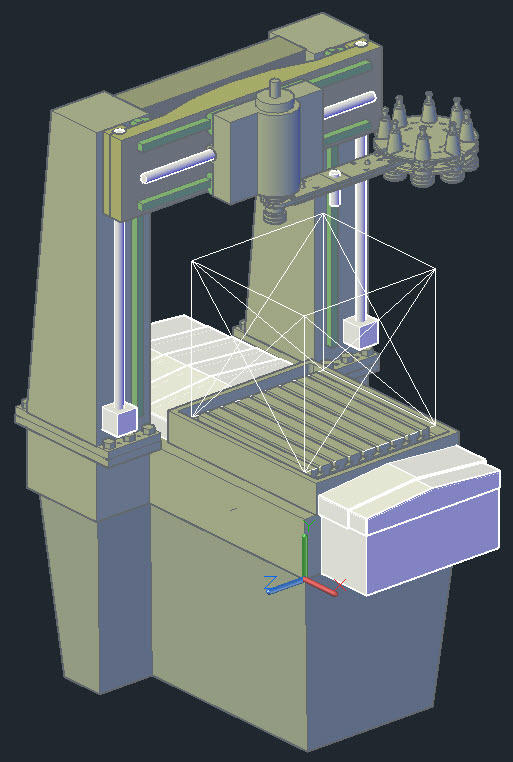
Hi All
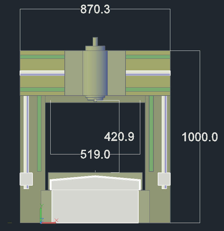
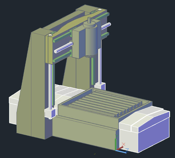
Its now 500x500x500
A fair bit of revision today… The base and columns have been redesigned for a bolted connection. The columns now sit on a foot their width has been increased to 200mm. This allowed me to raise the height of the columns while still allowing them to be cast over the Granite surface plate.
There is 80mm clearance under the tool holder shown to the top of the 500 cube, the tool holder itself is an 80mm projection. Plenty of room.
I have also sketched in a sub base; it could be Steel or concrete. Note that the machine will be supported at three points only.
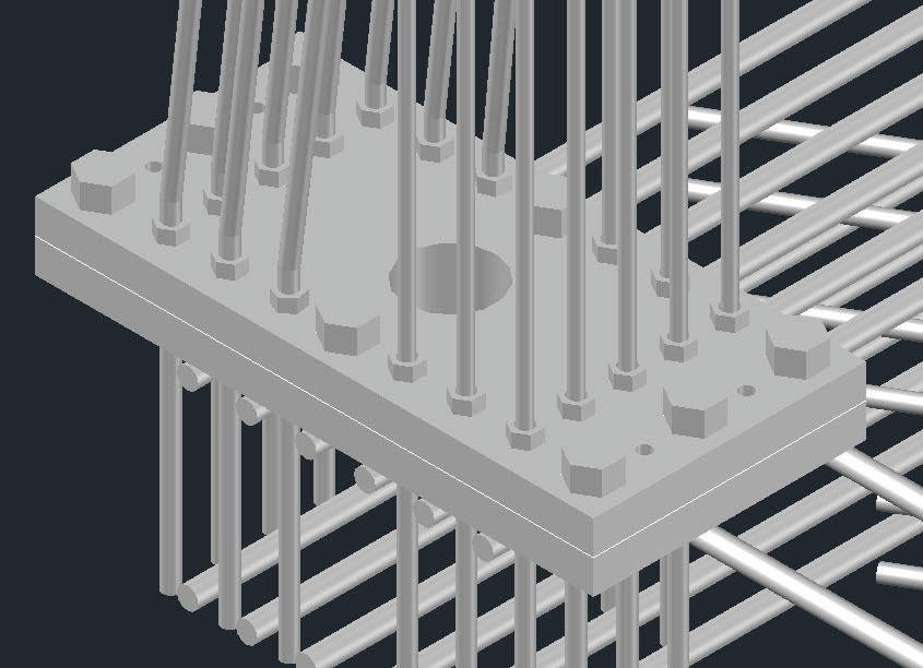
The connection between the column and the base is via a coupling comprising two 25mm steel plates and 8 M20 high tensile bolts (One plate is tapped the other has through holes. Three bolts each end and two in the centre.
There is also provision for 4 jack screws between the M20 nuts at each end of the plates. These will allow adjusting the columns square to the table. The gap if formed to be filled with my Epoxy Bearing Material. Once that is set the M20 nuts can be finally tightened down.
The plates are also drilled and tapped for M12 threaded rods that are screwed into the back of the plate and securely locked in place by a nut. This is essential to pre tension the connection prior to casting. Alternatively they could be welded.
I am very pleased with this design; it will be possible to adjust the machine very accurately.
Cheers
John
The latest file set can be found here:
http://www.mediafire.com/file/1rwrdn...28_04_2011.zip
-
04-30-2011, 07:09 AM #11
Junior Member
- Join Date
- May 2007
- Posts
- 68
Powerpoint and CAD of Epoxy Concrete CNC Mill design
Hi All
Version 30 April 2011
I have done a power point of the design project It better explains the objectives
It can be found here:
http://www.mediafire.com/file/4ez1io...%20CNCZ%20.ppt
The complete set of drawing files can be found here:
http://www.mediafire.com/file/tl0gv4...%20CNCZ%20.zip
Cheers
John

 Reply With Quote
Similar Threads
-
Epoxy-Granite machine bases (was Polymer concrete frame?)
By walter in forum Epoxy GraniteReplies: 5052Last Post: 02-08-2024, 12:42 AM -
Epoxy Granite In Practice (Mineral Casting, Polymer Concrete)
By johnohara in forum Epoxy GraniteReplies: 71Last Post: 08-25-2020, 01:18 PM -
Epoxy/granite machine concept
By Gizmot in forum Vertical Mill, Lathe Project LogReplies: 12Last Post: 02-28-2008, 09:46 PM -
Polyester concrete base. Can this work?
By alexccmeister in forum Mechanical Calculations/Engineering DesignReplies: 10Last Post: 07-13-2007, 04:13 AM -
Polymer enhanced Concrete Work Area
By jsage in forum Open Source CNC Machine DesignsReplies: 0Last Post: 01-29-2007, 11:37 PM
