


This is a build thread for the conversion of a Hafco HM52 to CNC control. The HM52 is a low cost entry level vertical knee mill sold in Australia by Hare&Forbes https://www.machineryhouse.com.au/ I believe it to be identical to many other "badge engineerined" low cost mills.
This is a hobby machine, not a production machine, as such I am not expecting the sort of rigidity and accuracy that you might expect from more expensive machines.
After some discussions with DaveJ (on another forum) I understand the base of the current production HM52 (HM52B) machines is strengthened by additional ribs in the casting, this might also apply to grizzly and other brands of the same machine I suspect. Makes me feel a little happier about proceeding with the conversion.
The inspiration for this project comes from chich2, who travelled down this path a few years back, see his thread here... http://www.cnczone.com/forums/showthread.php?t=25895
Some of the design decisions have been made based on problems that chich had with his conversion, so I owe a debt to his pioneering work.
1. ballscrews, I'm going for ballscrews first up. The costs have become much more reasonable in the last few years.
2. Whether to "Z" the knee or the quill. I am reluctant to go down the path of counterbalancing the knee and stiffening the column to base join, I feel (at this point) that it will be easier to deal with the quill run-out and flex than try to solve the base/column flexing. So I am going to drive the quill, and see what new problems might arise. The knee will be locked as normal while machining.
3. Selection of motors.
If we take mariss's example (from an earlier thread somewhere on cnczone)
Just starting somewhere... 120 ipm and 10lbs on a 6" handwheel
At 120 ipm with a 5 tpi ballscrew == 600 rpm on ballscrew
The torque is 10lb x 3 inches == 480 oz-in on ballscrew
The power required == 213 watts ( 600*480/1351)
Looking around ebay I found some yaskawa 400 W AC servos that will run on single phase 240V, there were some 750W Yaskawa's from the same supplier but they required 3 phase 240V, which I sadly don't have. So my "tim the toolman" approach to design has to be moderated a little.
Having decided on the 400W Yaskawa, we can now repeat the calculations above, and get some idea of the drive reduction.
If I go for about 3:1, what does that mean for speeds and torque?
The Yaskawa is rated at 3000 rpm, so that means ballscrew will be 1000 rpm at 5 tpi (actually the ballscrews I'm looking at are metric 5mm) the maximum will be 200 ipm, which is plenty fast enough for what I'm thinking.
Torque at the motor shaft will be 180 oz-in (from motor data) times 3 (reduction drive) == 540 oz-in (at the ballscrew) with peak torque (during accell/decell ) of 1620 oz-in
4. Control Systems,
The servo amplifiers are yaskawa which came with the motors, and can be set up in a number of different ways, The encoder is matched in some way to the drive, I think I read somewhere that the drive actually communicated with the encoder to identify motor type etc.. for what I am intending this doesn't really matter, the drive generates quadrature encoder and index signals (nicely opto-isolated btw) that will be fed to a mesa 5i23 (buffered by a mesa 7i33TA interface board.
The mesa 5I23 is a FPGA pci bus board that handles the encoder interface and servo control.
The mesa 7I33 is an interface board for the mesa 5I23, and provides noise filtering for the encoder pulses, and also generates the +-10V drive signals for the servo amp.
The Yaskawa drive can also run in step/dir mode with a breakout board and Mach3, in fact I'm running that way at present (bench testing), while waiting for the mesa boards to arrive. You just have to set some parameters in the drive.
The CNC software will be EMC2, still haven't decided on a PC platform as yet, but running the live CD, it looks to have everything I will need and more..
That's about it for the time being, I should be picking up the mill in the next few weeks, so I'll post some more then, I hope that others can learn from my screw ups as I go along..
Regards
Ray
Thread: Hafco HM52 CNC Conversion
Results 1 to 20 of 54
-
03-10-2010, 07:38 AM #1
 Registered
- Join Date
- Feb 2010
- Posts
- 0
Hafco HM52 CNC Conversion
-
03-10-2010, 08:18 AM #2
 Registered
- Join Date
- Feb 2008
- Posts
- 69
I will be watching this thread with interest Ray. Always looking for more ideas for mine.
Dave
-
03-12-2010, 01:27 PM #3
Registered
- Join Date
- Oct 2009
- Posts
- 9
Greetings Ray
Got an email from Davo J about this post. I too am on the path to convert my HM52. I have stalled due to other committments.
I picked up three ball screws today (12/3/10). I was talking to these two young blokes I know who run an excellent CNC shop near me and one of them had three ground ball screws and nuts for a conversion he was going to do but got the real machines instead. The screws are 30 Dia 5 mm pitch with loaded nuts (internal recirculating with negative clearance). He paid $1200 each for them and wants me to make an offer. I still am of two minds as to what to do as they are only 800 mm long so that means I would have to adapt the x axis screw for the overall length (it will accommodate the travel). I will have to dismantle the table next week and have a look underneath before I go any further. I really haven't had any time (or the inclination) as I have been extremely busy with a business I have started up and it has really taken over things at the moment. Just on the day I picked up these screws then an email from Davo J - maybe an omen to get stuck into it!!!!
I haven't bought the screws yet but he insisted I take them home so they weren't lying around his workshop (they are still all wrapped up and boxed) and I was to make an offer if I was interested. I am just about ready to purchase all the screws, motors (1100 oz) and controller sometime next month. I am going to purchase all the components first then tackle the job. That’s the plan anyway. Look I need all the encouragement I can get and it maybe the thing to awake me into action. I too will be watching your progress and maybe Davo J and I can contribute and at best be stirred into action.
Regards Alick
-
03-12-2010, 02:42 PM #4
Registered
- Join Date
- Feb 2010
- Posts
- 0
Hi Alick,
Dave mentioned that he knew someone about to start the same project, so, welcome, I'm planning to push ahead pretty quickly in the next few weeks. The Mesa boards have arrived, (pretty amazing delivery for half way round the world!) I will be wiring them up and doing some bench testing of the motors and drives in the next few days. I'll put up some circuit diagrams and pictures.
As for the ball screws, I think that's a premium price, I don't doubt that they are worth every penny for a precision ball screw. My sights are set a bit lower and I am hoping to pay a lot less... The supplier I'm looking at is this one..http://stores.shop.ebay.com.au/linea...__W0QQ_armrsZ1
Probably not as good as yours, but a lot less dollars. I'm holding off on buying the ball screws until I have a better idea as to exactly what lengths and mounting arrangement I need.
My background is industrial controls, embedded systems and real time linux based control systems. Dave has a lot of experience and knowledge with the HM52 and engineering background.
Should be a good project.
Regards
Ray
-
03-13-2010, 01:35 AM #5
Registered
- Join Date
- Oct 2009
- Posts
- 9
Hi Ray
Looking forward to follow what you are doing. The three ball screws and nuts are being offered to me for what I would have to pay for one screw in today’s price. The person had paid $1200 per screw (with nut) when he bought them. Basically he is offering me the lot for about $1200 or ?.
It’s hard when you are dealing with people you know but these guys are 100% genuine and have also offered to help in so many ways. It’s just a matter of getting started. My contact with you and Dave will certainly spur me on. My background is fitting and machining (heavy) – taught in the tafe system for quite a few years - my son is also a fitter/machinist/toolmaker with a good background in electronics and robotics so I will be relying on his knowledge and experience – I am just an old fart (with hopefully a young mind) trying to keep up with things and enjoy myself in the bargain. My workshop contains a AL 336/D Lathe (new), HM-52 Turret Mill (new), KAO MING KM-40S Tool and cutter grinder, Alexander Pantograph (next CNC project after the mill) plus the usual workshop accessories.
Cheers
-
03-13-2010, 02:10 AM #6
Registered
- Join Date
- Feb 2008
- Posts
- 69
Hi Alick,
Just check and make sure the 30mm nut will fit under the table. With 600mm travel and a 800mm screw doesn't give you much to play with. You would have to put the ball nut on the end of the saddle like Chich2 has done, but with a floating end as I said in the PM.
The price I got from LMBearings was $28US per nut and $49US per meter of screw plus postage. That only works out to be around $200US plus around $100US postage.
Davo
-
03-18-2010, 12:25 AM #7
Member
- Join Date
- Jun 2006
- Posts
- 475
Ray,
I'll be watching this thread with interest. Interested to see your angle on how you choose to convert your mill. I hope you enjoy every part of the conversion as I did.
Chich
P.S. Thanks for mentioning my thread.
-
03-26-2010, 12:43 AM #8
Registered
- Join Date
- Feb 2010
- Posts
- 0
Time for an update.
The particular model HM52 I wanted wasn't in stock and deliveries are due mid April, so in the meantime, I am re-organizing the workshop to make room for when it arrives. Added extra power points for the CNC and storage for tooling. Looks strangely clean for a change.
The Aluminium plate for motor mounts has arrived, 1/2" 6061 T6 and ballscrews and ac bearings have been ordered.
The ballscrews are from this guy. http://stores.shop.ebay.com.au/linea...__W0QQ_armrsZ1
I have ordered RM2505, 25mm diameter and 5mm per turn pitch.
The AC bearings, are from http://www.vxb.com/page/bearings/PRO...ONTACT/Kit1087
The computer is now ready to be set up, I'm using a shuttle pc with compact flash for the hard drive. I chose the shuttle because of the compact size and good cooling.
All the Yaskawa servos have been test run and look to be all ok.
The 240v VFD for the spindle speed has arrived and the spindle motor as well, although not tested yet.
So all the bits and pieces are almost here, just waiting on the machine itself. Which will be a couple of weeks.
So back to learning what I can about EMC2...... nice system.
Regards
Ray
-
04-09-2010, 10:01 AM #9
Registered
- Join Date
- Mar 2004
- Posts
- 142
I'll be following this thread. I'm curious as to how you plan to preload these bearings. I'm also in the planning stages for the cnc conversion of my Rambaudi V2. I've got all the spindles and servos. Now I need to work out how to mount them to minimize backlash.
Erik JanWhat goes down, should come up.
-
04-09-2010, 11:50 AM #10
Registered
- Join Date
- Feb 2010
- Posts
- 0
Hi Erik,
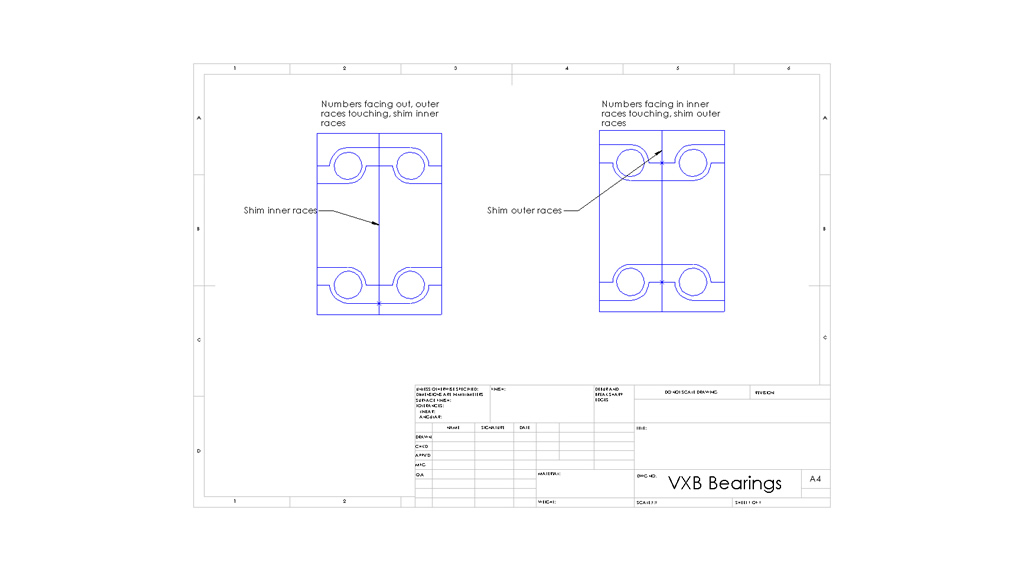
Thanks for your interest, I haven't finalized anything yet, but the following diagram illustrates how I am thinking of doing it.
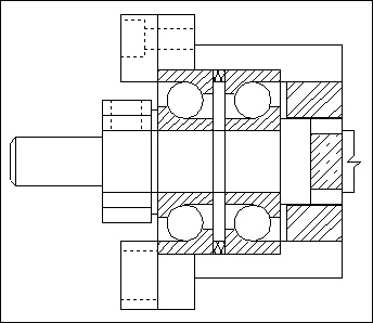
The idea, is to put shims between the bearing pair that will apply a preload to the bearings when the screws holding the retaining cap are tightened.
That drawing is from another thread here on cnczone... I can't seem to find the link at present.
Regards
Ray
-
04-10-2010, 12:56 PM #11
Gold Member
- Join Date
- May 2006
- Posts
- 2420
Hi Ray, keen to see how you go with the retrofit, I probably can't help all that much but will keep watching anyway

Russell.
-
05-10-2010, 06:59 AM #12
Registered
- Join Date
- Feb 2010
- Posts
- 0
HM52 finally arrives
Time for a progress update on the project.
The HM52 arrived last week, after a month waiting it's good to finally have the machine so we can finalize some of the design questions.
We are starting by installing the ballscrew on the X axis, and then using that experience convert the Y-axis to ballscrews.
Here is the bottom of the cross slide for the table.
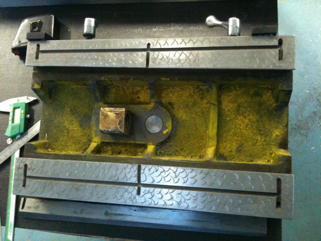
A new ballnut mounting something like this will replace the existing leadscrew nut
After some discussions with RodM and DaveJ on the other forum, it was decided that we needed a means of adjusting the rotation of the ballnut, so the bolts will come in from the bottom of the crossslide, (so they can be accessed when the table is assembled with the cross slide in place) and the holes will be a little oversize to allow for the ballnut to be aligned by running end to end before finally tightening.
The x-axis power feed is on the right hand side (that's the free end of the ballscrew), and the thrust bearings are on the left, so we will retain the existing bearing support on the right hand end, and reference everything from the axis of the existing leadscrew. That means we have to machine the ballnut mounting surface slightly lower to keep the centerline of the ballnut in line with that reference point. After a lot of mucking around we referenced from the ground surface of the dovetail slide and will machine that with the table removed, and the crossslide rotated 90 degrees and using the Y-axis feed and turret to machine the ballnut mounting point.
The new servo mounting plate and AC bearing block will go on the left hand end, and the plan is to re-assemble the machine and using a center finder with the DRO as a digitizer to digitize the hole locations to match the existing centers.
Meantime, on the controls side the wiring on the servo test bench is complete and up and running. We are using EMC2 to close the loop at the PC, the Yaskawa drives are running in velocity mode driven by +-10v signals from a Mesa 7i33/5i23. The encoder signals are generated by the drives, the cable running from the drive to the encoder has serial data and the drives communicate with the motors in some fashion... The drive controller then re-generates the encoder output which goes the 7i33, one little gotcha is the servo_enable on the Yaskawa is 24v opto-isolated input so the output from the 7i33 for servo_on will need to be buffered with a small opto board. The drive has provision for scaling the encoder output, and the default setting is 16384 pulses per rev, but the encoders that were fitted to our motors were only 13bit, 2048 pulses per rev. So if you are using Yaskawa drives, check the encoder resolution, the factory default setting is wrong..
When first powered up and enabled, we kept getting joint following errors, and had to increase the error tolerance until we could get the PID tuned somewhere close, so that we weren't getting wild oscillations..
The PID inside the drive, is cascaded with the EMC2 PID, so tuning can be tricky until you get somewhere close..
Here is our setup running the EMC2 demo
[nomedia="http://www.youtube.com/watch?v=y4LohuMTdfo"]YouTube- HM52 CNC conversion. Part 1[/nomedia]
Here are the hm2-servo.hal files and the 5i23.ini files for the test setup.
Please note we actually don't have a machine with 30 meters of travel, edit to whatever suits your setup...
Regards
Ray
-
05-10-2010, 07:24 AM #13
Registered
- Join Date
- Feb 2010
- Posts
- 0
Servo Bench Test
Anyone know what the procedure for embedding youtube videos is?
Just pasting the embed tag doesn't seem to work?
<object width="480" height="385"><param name="movie" value="http://www.youtube.com/v/y4LohuMTdfo&hl=en_US&fs=1&rel=0"></param><param name="allowFullScreen" value="true"></param><param name="allowscriptaccess" value="always"></param><embed src="http://www.youtube.com/v/y4LohuMTdfo&hl=en_US&fs=1&rel=0" type="application/x-shockwave-flash" allowscriptaccess="always" allowfullscreen="true" width="480" height="385"></embed></object>
Let's try this way..
<embed src="http://www.youtube.com/v/y4LohuMTdfo&hl=en_US&fs=1&rel=0" type="application/x-shockwave-flash" allowscriptaccess="always" allowfullscreen="true" width="480" height="385"></embed>
Ok, what about..
http://<object width="480" height="385"><param name="movie" value="http://www.youtube.com/v/y4LohuMTdfo&hl=en_US&fs=1&rel=0"></param><param name="allowFullScreen" value="true"></param><param name="allowscriptaccess" value="always"></param><embed src="http://www.youtube.com/v/y4LohuMTdfo&hl=en_US&fs=1&rel=0" type="application/x-shockwave-flash" allowscriptaccess="always" allowfullscreen="true" width="480" height="385"></embed></object>
Hmm... never give up
[youtube]y4LohuMTdfo[/youtube]
Regards
Ray
-
05-10-2010, 10:04 AM #14
Gold Member
- Join Date
- May 2006
- Posts
- 2420
Hi Ray, you are most likely doing it right, I tried to embed a video a few days back with no success, have done it several times in the past. I ended up just copy and pasting the link into my response. I have seen this in the past on this site when video's don't embed, after a while they seem to work again.
Cheers.
Russell.
-
05-10-2010, 10:12 AM #15
Gold Member
- Join Date
- May 2006
- Posts
- 2420
Try this for now :
http://www.youtube.com/v/y4LohuMTdfo..._US&fs=1&rel=0
Cheers.
Russell.
-
05-10-2010, 10:20 AM #16
Registered
- Join Date
- Feb 2010
- Posts
- 0
Hi Russell, Originally Posted by epineh

Thanks for that, having never posted a youtube video here before, I just assumed it was something I was doing wrong. The other vbulletin sites, where I have posted video you can just paste it as a link, and then the system picks up on the youtube url and does the rest.. I guess?
Regards
Ray
-
05-12-2010, 08:55 AM #17
Registered
- Join Date
- Feb 2010
- Posts
- 0
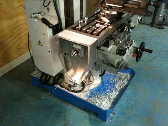
X-axis ballnut mounting
The ballnut mounting for the X-axis is now finished.
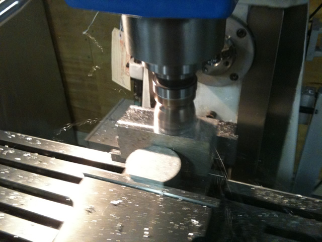
Squaring up and facing the stock, the finish from the indexable face mill is nice.
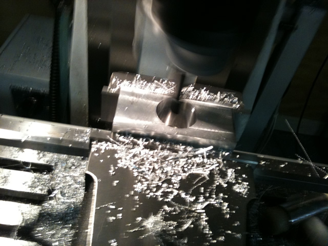
Boring the 40mm hole for the ballnut.
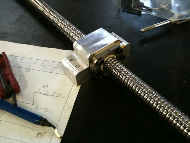
The finished part, with a bit of chamfering to clear the bottom of the table dovetail.
The ballnut mounting holes locations were transfer punched using the ballnut as the template
and then tapped for M6, the holes for mounting to the cross slide are tapped M8 and the holes
in the crossslide will be drilled oversize to allow for alignment.
Only design issue I can see at this stage is the grease nipple needs a little more clearance.
Next task is to finalize the design and making of the servo mounting plate.
Then machining of the ballscrew ends will be after that.
Regards
Ray
-
05-13-2010, 06:11 PM #18
Registered
- Join Date
- Feb 2010
- Posts
- 0
Machining Ballscrew ends
Time for a late night update
It's getting close to the time for machining the ballscrew ends, so I figure I should make sure it's going to work.
The critical things are, not to damage the ballscrews, so the ballscrew is held in a brass "collet" of sorts,
the ballscrew passes through the spindle and there is a plastic insert to center the ballscrew and provide a bit of support.
There is a few layers of tape to stop the ballnut from unwinding off the ballscrew.
I don't want to have to learn how to reload ballnuts just yet..
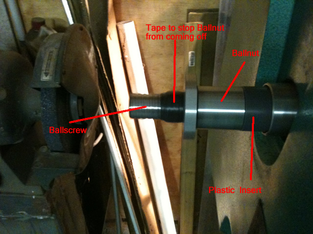
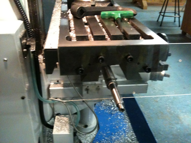
Here is the back of the lathe spindle.
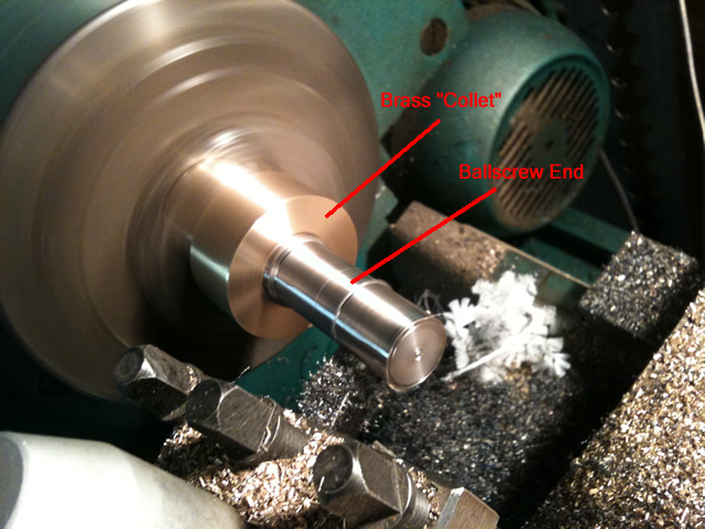
The brass collet setup.
The brass "collet" is machined to be a sliding fit over the ballscrew, and I have cut slits in the section
where it is clamped by the chuck. The runout is checked with a dial test gauge. I didn't feel the need
for a center on the tailstock, but machining longer sections I might need it.
The ballscrew is hardened, but as RodM had pointed out earlier, one you get through the hardened threads
it went fairly smoothly with TC insert cutters. Light cuts and low feed rate until you get past the ball threads.
Interrupted cuts on hardened material (not to mention expensive parts) make for nervous machining...
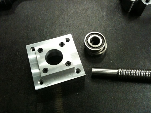
Here is the finished test part. With the AC bearings and bearing housing.
The idea here was just to do a test to see how easy it would be to setup and how hard it would be to machine,
expensive little things these ballscrews, can't afford to have any stuffups.
So far so good...
Regards
Ray
-
05-21-2010, 02:04 PM #19
Registered
- Join Date
- Feb 2010
- Posts
- 0
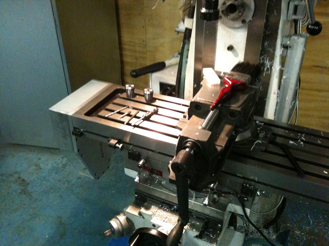
x-axis conversion continued
Time for an update on the progress of the x-axis conversion to ballscrews.
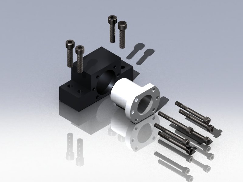
Here is the final x-axis servo mounting design.
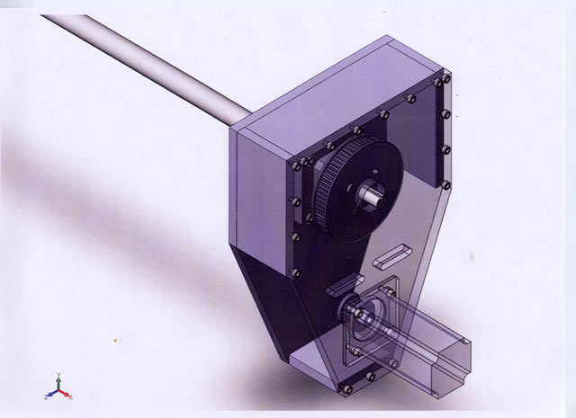
Some pictures of the build so far.
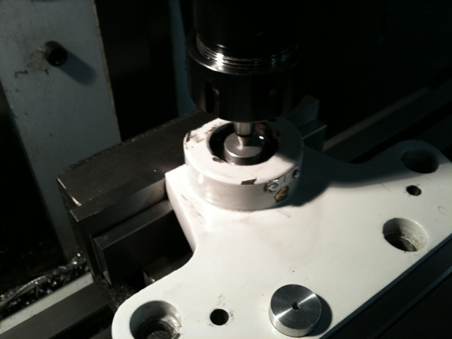
Using the dro to digitize the hole pattern on the end of table.
Made a test part using acrylic to double check the hole locations. Once
finally locked down there will be a couple of new dowells fitted.
Test fitting the servo mount, the bottom panels are perspex.
The next job is to machine the ballscrew ends, now that we can get the final dimensions. After that it's time to pull the table off and machine the ballnut mounting , at that stage we will be running the x-axis with ballscrews, no servo control yet..... but almost...
Credit for the machining goes to my son Josh who has done an outstanding job.. One day, I might get to have a go too...
Regards
Ray
-
05-21-2010, 02:19 PM #20
Registered
- Join Date
- Feb 2010
- Posts
- 0
VXB AC Bearings
Some test fitting and preload setup for the vxb ac bearings.
Here is a sketch of the bearings,
After reading all the posts I could find on cnczone.. (lots of them) on how to set up the preload, I was
more confused than ever, so I set up a test system to try a few different things.
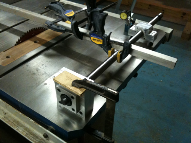
The bearing block is clamped to the table saw table, and a dial test guage is
set up to watch the movement of the ballnut. (later I clamped the ballnut to the table to simulate a load)
I clamped a 6' aluminium tube to the ballscrew, so I could get really small amounts of rotational movement of the ballscrew. Just rocking the end of the aluminium tube slightly produced deflection back and forward on the dial guage. (minimum divisions 0.01mm)
The bearings are stacked numbers out, large inner races facing inwards, and when clamped up the outer races were touching and the inner races slightly loose. So I made shims for the inner races.
I couldn't detect any backlash with 1 thou shims, and I could feel a very slight increase in drag when compared with no shims, when I increased the shim to 2 thou, there was a noticable increase in drag, but still no measurable backlash.
The setup for making the shims is pretty basic, just a stanley knife and a pair of scissors.
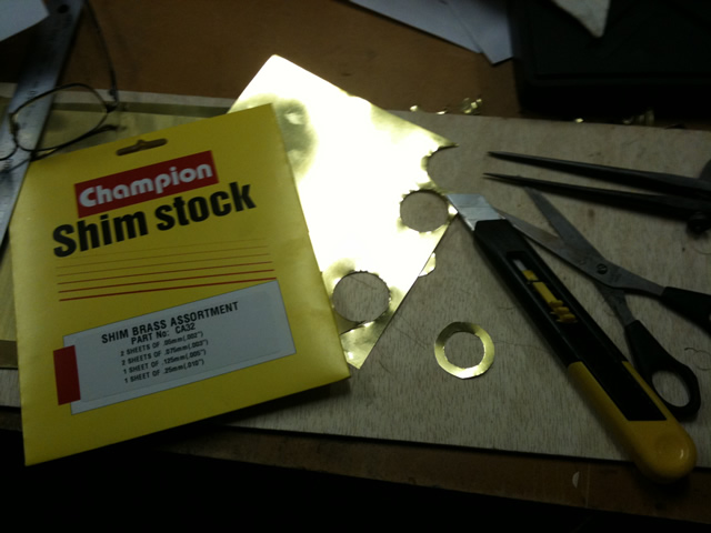
I will probably go with 1 thou shims, but now I have a much better handle on how to go about the setup.
I can wait to see what it's like when installed on the mill, then fine tune a bit if needed.
Regards
Ray

 Reply With Quote
Similar Threads
-
Hafco Metal Master HM-52 CNC Conversion
By chich2 in forum Vertical Mill, Lathe Project LogReplies: 327Last Post: 11-28-2014, 12:47 PM -
Hafco CNC Conversion
By Johnnysilk in forum Australia, New Zealand Club HouseReplies: 8Last Post: 04-16-2013, 09:30 AM -
HAFCO VM1
By Steveb1307 in forum Australia, New Zealand Club HouseReplies: 3Last Post: 04-04-2010, 09:09 PM -
4 Axis DRO Fitout to Hafco HM52
By DMBGO in forum Knee Vertical MillsReplies: 9Last Post: 07-27-2009, 01:27 PM -
Perth Hafco HM35 CNC Conversion
By XaserTech in forum Australia, New Zealand Club HouseReplies: 0Last Post: 01-09-2009, 01:06 AM
