


Ray, I shall follow with much interest. I need to choose suitable motors and drivers for my King Rich Mill conversion. Your knowledge of industrial control will prove invaluable and your progress so far on your project is very impressive.
Cheers,
John
http://www.cnczone.com/forums/showthread.php?t=105668
Thread: Hafco HM52 CNC Conversion
Results 21 to 40 of 54
-
05-22-2010, 08:03 AM #21
 Registered
- Join Date
- Sep 2008
- Posts
- 157
-
08-08-2010, 09:10 AM #22
Registered
- Join Date
- Feb 2010
- Posts
- 0
I got a bit of time to do the VFD spindle conversion, after deciding to use the MESA 7I47S I/O card for spindle control, I have ordered one, but delivery will be in October, so in the meantime I want the ability to manually override the automatic control anyway.
A PDF of the preliminary circuit design is here ... http://www.backsaw.net/pics/HM52_Spindle_Circuit.pdf
The circuit diagram contains notes on modifications required to the HM52 wiring.
The motor I got was a 1.5kw TECO (from ebay) and the VFD happened to be a TECO FM50 (again off ebay)
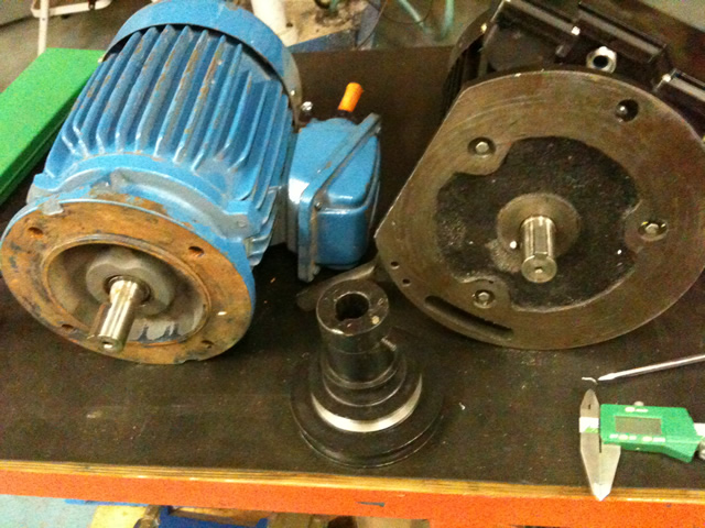
The shaft diameter and keyway was the same as the original motor, which made things a bit easier.
The flange mounting bolts are the same on both motors, it's a standard 90L frame but the spacing and bearings are different, so I have to make an adaptor plate.
This was cut from 1/2" aluminium plate on the bandsaw and finished by hand (no mill you see!)
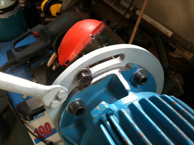
The flange on the teco interferred with the mounting bolts so I had to grind a bit off the flange to clear the washer.
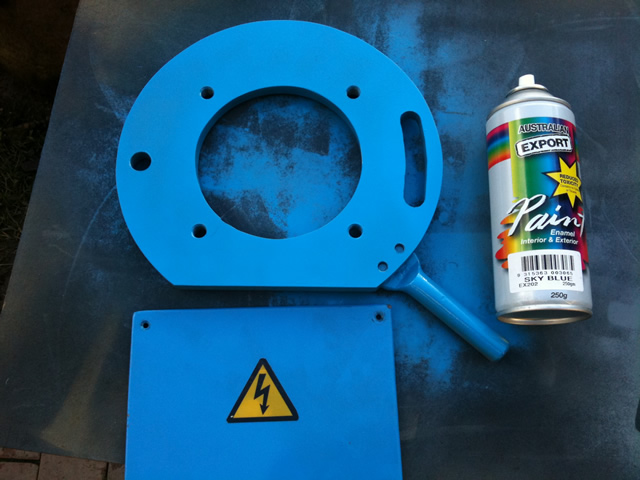
The finished adaptor plate, the colour is "sky blue" to match the H&Fcolour scheme..
I cleaned the motor and primed it with Galmet and then painted it to match.
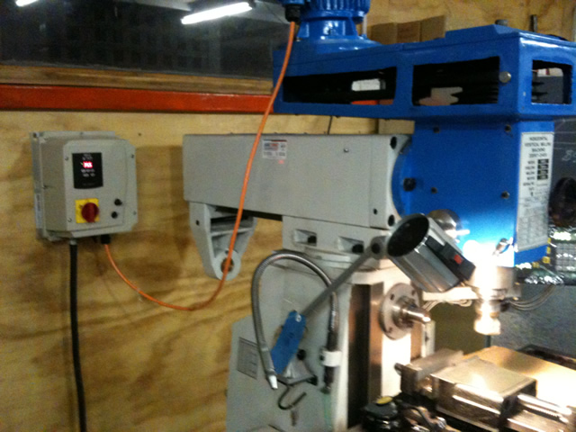
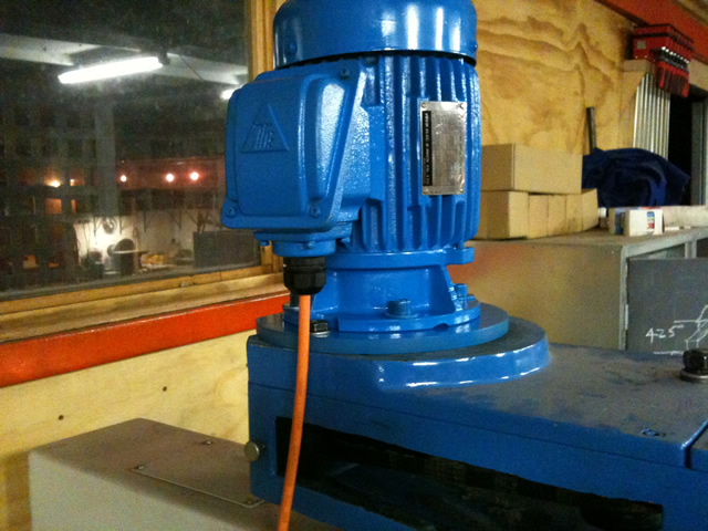
VFD temporarily mounted on the wall, The new control panel will go on the front of the machine, where the H&F nameplate used to be. This frees up the side of the Quill for the Z axis.
The front panel will have a RPM display which will pick up the spindle speed directly from the spindle itself, so that when adjusting speeds
the belt configuration is automatically corrected for.
Regards
Ray
-
08-08-2010, 11:15 AM #23
Member
- Join Date
- Jun 2006
- Posts
- 475
Nice job Ray,
Keep up the good work,
Chich
-
11-10-2010, 01:00 PM #24
Registered
- Join Date
- Feb 2010
- Posts
- 0
Z axis progress update,
After playing around with dozens of variations of different ways to do the bearings, I finally settled on NSK 7912A5 AC bearings and housed in a cast mount.
Here is the general arrangement

The quill return spring stays, but with a different spring, tensioned to just balance near the top of the travel. The back of the ballscrew bearing mount is cut out to accomodate the quill return spring.
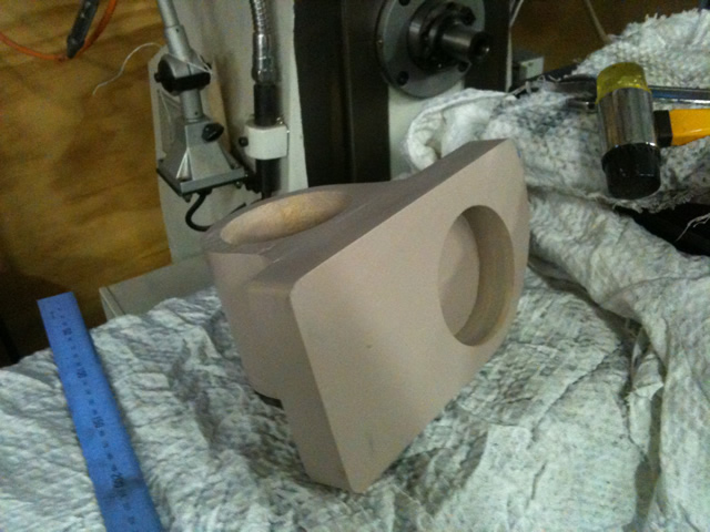
I still have to make the core molds, and the parting line will be centered on the axis of the main bearing. The quill spring cutout will be filled in before casting, and machined out after.

The center of the quill clamp need to be built up before casting, to accomodate any shrinkage, and then machined to finished size afterwards.
Material will be aluminium bronze.
The side of the mill where the bearing mount is going to go is dished and the next job is to try and flatten it as much as possible..
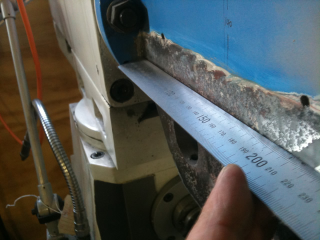
I've got most of the bog off and now trying to come up with some way of flattening it..
Regards
Ray
-
11-10-2010, 01:49 PM #25
Member
- Join Date
- Jun 2006
- Posts
- 475
Nice work mate!
Can I suggest removing the head and mounting it to your table. Then you can mill it flat with your horizontal spindle. You will either have to electricaly disconnect your vertical spindle motor OR just remove your vertical spindle motor and hang it from a rope out of the way while it is removed.
Cant remember if the standard cable is long enough to just leave it all connected or not???????
Watching with interest,
Chich
-
11-11-2010, 09:23 AM #26
Registered
- Join Date
- Feb 2010
- Posts
- 0
Thanks, Chich, the motor cable was long enough to leave it connected.
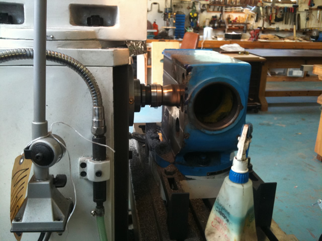
No sense in waiting around, I stripped the head assembly as much as I could, using the knee to support the spindle and gently lower it out, worked a treat.
No need to disconnect the motor wiring, just unbolt the motor and leave connected.
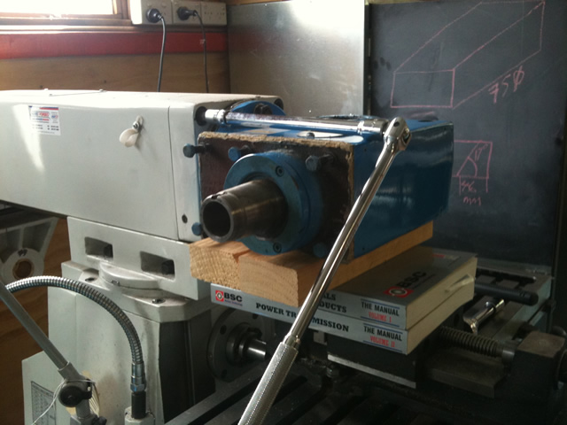
Thanks Dave (on the other forum) for the advice on removing the head, those big 12mm hex bolts have to come off first. The head is trapped by the gear/worm drive that does the head rotation.
I used the Knee, wound all the way up, and a bit of packing to support the head, and then when it came loose, used the Y axis to back it out of the column. No heavy lifting required. (No swarf in the worm drive either)
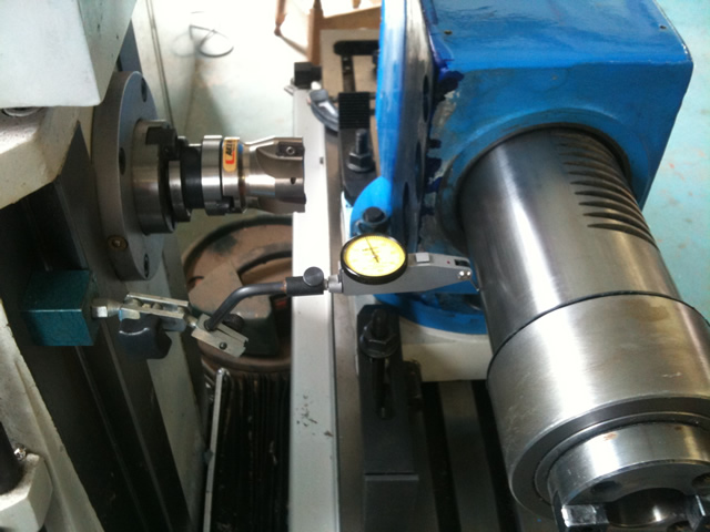
I put the spindle back to use as a reference to tram the assembly alignment to the X axis table. With a DT indicator.
Lots of light passes, in hindsight, I probably could have done it two cuts, but it's a bit nerve racking watching your mill slowly eating itself..
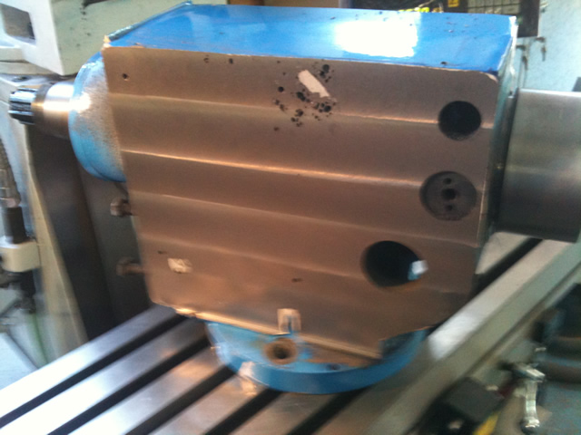
At last a flat surface, parallel to the spindle.
The machining uncovered a few porous patches in the casting, not sure justyet, but a bit of bog seems to be the original manufacturers cure for all these issues...
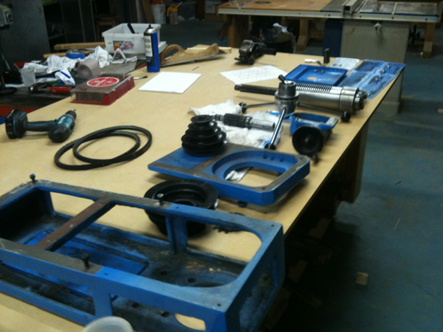
Now where do all these bits go?
Next job is to get setup to cast the quill clamp and the ball nut bearing support.
Regards
Ray
-
11-11-2010, 11:29 AM #27
Registered
- Join Date
- Jun 2010
- Posts
- 0
What can I say?
Apparently you have done a good job. I might try what you have done in the future.
Best regard,
rusty.
-
11-11-2010, 12:12 PM #28
Member
- Join Date
- Jun 2006
- Posts
- 475
Excellent work. That was "the right way" to do it. You have done a nice job!
Chich
-
03-09-2011, 06:21 PM #29
Registered
- Join Date
- Jul 2006
- Posts
- 13
Step/dir configuration of yaskawa drives
Ray,
Excellent work, congrats!
Can you share with us the parameters you set in the Yaskawa drives so they run in step/direction mode? Did you hook them directly to the parallel port to read the step and dir signals?
I am building a gantry router, and trying to instal 3 yaskawa motors and drives, but the drive configurations are tricky, and I am lost ...
Drives are SGDH-08AE-S with matching motors
Best regards,
Dimitrios
-
03-10-2011, 12:49 PM #30
Registered
- Join Date
- Feb 2010
- Posts
- 0
Hi Dimitrios,
The project is in a parts acquisition mode for the next phase of the conversion. I hope to start finalizing some of the design in the next month.
Thanks for the comments, I didn't use the step/dir inputs, I used a Mesa 7133 with +-10v analog output.
However I did earlier-on power the drives up and used a parallel port card that came with the drives to just make sure that they ran ok.
The manuals I have are for the SGDM series, but you can download manuals for the SGDH from here
Download
If you are interested I can get the drive configuration, I'm using for the analog position mode.
Regards
Ray
-
03-11-2011, 10:56 PM #31
Registered
- Join Date
- Jul 2006
- Posts
- 13
Ray,
Many thanks for your answer. It was enlightening, but i do not want to hijack your thread wit my own problems :-) . I will stick to driving the motor directly (sort of, we are building a line driver to do it) from the parallel port. Yesterday we solved the first problem (parameter settings).
If you are intersted, I can send you a PM explaning it better.
I will keep reading your excellent thread.
Best regards,
Dimitrios
-
03-12-2011, 05:19 AM #32
Registered
- Join Date
- Feb 2010
- Posts
- 0
Hi Dimitrios,
The drive configuration for +-10v analog control
Pn000 Digit0 =0 Digit1=0 (analog reference) You would use 1 here for pulse train reference
You wouldn't use these parameters, I don't think.
Pn100 = 20 (gain)
Pn101 = 5000 ( 5 seconds)
Pn300 = 1000 (10v=100%)
The connection to the parallel port, is step signal supplies current to opto isolator in the drive, via pins 7&8 and direction signal to 11&12.
The overtravel inputs inhibit drive output in the direction of travel, so you can still reverse off the limit switches. You need an external 24v dc supply to drive these..
+24v dc goes to pin 47, and 24v ground is switched to the inputs.
Refer to the circuit diagram in the manual for confirmation that your model is the same as mine.
Pin 40 is servo on
Pin 42 is forward inhibit
Pin 43 in reverse inhibit
I'm leaving out other connections, but you need to supply power to these inputs to get the servo running. Especially the inhibit inputs, when these are OFF the servo is inhibited (fail safe)
Regards
Ray
-
03-12-2011, 05:40 PM #33
Registered
- Join Date
- Jul 2006
- Posts
- 13
Ray,
That is what we did, less the analog parameter settings, since we do not use analog.
We are having trouble with the parallel port signal, which we do not pinpointed yet.
Thank you very much, I will tell you what we did after tomorrow, since all the gear is in the yaskawa rep office for testing.
Regards
-
03-19-2011, 12:39 AM #34
Registered
- Join Date
- Mar 2011
- Posts
- 0
Nice conversion!
do you loose any of the Y axis travel when converting to ball screws/nuts?
-
03-19-2011, 03:18 AM #35
Registered
- Join Date
- Feb 2010
- Posts
- 0
Hi Landslide,
I haven't done the Y axis yet, but I don't expect to lose any Y axis travel in the conversion.
I will move the factory fitted X axis scale from the rear of the table to the front, like DaveJ has done with his mill.
See the link here...
Installing a DRO scale on front of table HM50/52 - Woodwork Forums
The mill as supplied with DRO has a Y axis travel of 160mm stop to stop.
Wheras the specifications are for 220mm Y axis travel.
With Dave's modifications that should end up around 280 mm Y axis travel.
Regards
Ray
-
03-19-2011, 10:48 AM #36
Registered
- Join Date
- Feb 2008
- Posts
- 69
I am still watching on with interest Ray.
This is the Y axis extension Ray is referring to.
Hm50-52 Y axis extension (160 to 280mm+) - Woodwork Forums
Dave
-
03-21-2011, 10:05 AM #37
Registered
- Join Date
- Mar 2011
- Posts
- 0
thanks for the info. after looking at a few drawings using two ball nuts back to back to eliminate backlash I was wondering if the Y axis would suffer.
it is really tempting to buy one of these mills and try a conversion also.
the z axis is the only thing holding me back. chich2 seemed to have good success using the knee, but latter in the thread the issues start appearing.
using the quill as the Z looks just as intimidating.
good luck, looks like great fun.
-
08-07-2011, 10:17 AM #38
Registered
- Join Date
- Feb 2011
- Posts
- 0
Hi Ray, I am trying to interface Yaskawa SGDH-02AE ServoPacks with Mach3 using Step/Direction using the SN75174 line driver interface. Do you have any idea what the ServoPack parameters should be? I tried the parameters you listed above in this thread for +-10v analog control. These settings had no effect on my results. Is the +-10v analog control considered Open-Collector with with an external power source? Do you have any idea what to do with pins 14 & 15 "Clear"? Any advice you can offer would be greatly appreciated.
Ray
-
08-07-2011, 01:36 PM #39
Registered
- Join Date
- Feb 2010
- Posts
- 0
Hi Ray,
The analog input is a voltage input that varies from -10v to +10v, to use the step direction inputs you don't use the analog signals.
You want to configure it for digital inputs NOT analog. The digital outputs are from the parallel port (on your PC running Mach3) and need to be buffered to drive the digital inputs on the servopack.
If you look at this circuit diagram, you will see that all the signals you need to drive the servopack are driving opto-isolators inside the drive, so you need to supply external power to drive the signals.
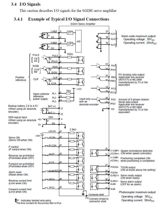
The step signal connects to PULSE input, and the direction input connects to the SIGN input, you don't need the CLR signal. make sure you get the polarity correct.
The other signals you need are the 24v dc signals that is the switch inputs as per the diagram above.., S_ON, and don't forget the limit switches should be connected to the N_OT and P_OT, if you are just bench testing, then you can just wire these inhibit inputs to be on all the time. But the idea is that the travel limit for forward will inhibit forward motion, but not inhibit reverse, so you can back off the limit switches under program control. If you don't provide these signals the drive won't run.
Finally...
The configuration should be set to pulse train reference.
This is Pn000 digit 1 == 1
Do you have the manual?
Regards
Ray
-
08-08-2011, 12:55 AM #40
Registered
- Join Date
- Sep 2008
- Posts
- 157
Position control
Letray,
I have Samsung drives, which are very similar and use the same connection terminology, running using Mach3 and a simple buffer board. I have later added a smooth stepper board to improve motion control and reliability.
http://www.cnczone.com/forums/891316-post60.html
Takes a bit to get your head around but I hope you find something there that is relevant to your project.
Cheers,
John

 Reply With Quote
Similar Threads
-
Hafco Metal Master HM-52 CNC Conversion
By chich2 in forum Vertical Mill, Lathe Project LogReplies: 327Last Post: 11-28-2014, 12:47 PM -
Hafco CNC Conversion
By Johnnysilk in forum Australia, New Zealand Club HouseReplies: 8Last Post: 04-16-2013, 09:30 AM -
HAFCO VM1
By Steveb1307 in forum Australia, New Zealand Club HouseReplies: 3Last Post: 04-04-2010, 09:09 PM -
4 Axis DRO Fitout to Hafco HM52
By DMBGO in forum Knee Vertical MillsReplies: 9Last Post: 07-27-2009, 01:27 PM -
Perth Hafco HM35 CNC Conversion
By XaserTech in forum Australia, New Zealand Club HouseReplies: 0Last Post: 01-09-2009, 01:06 AM
