


I've noticed that I have 0.086" backlash on the Z axis on my SX3 machine. I get about the same value from the spindle or the head block so that rules out the spindle assembly.
I believe the backlash comes from the coupler over the Z axis ballscrew under the back cover plate.
My question is how to adjust out the backlash? I know the four screws need to be tightened, but, how much and how do I know how much?
Wayne
Thread: Z axis backlash.
Results 1 to 20 of 22
-
07-11-2008, 08:54 AM #1
 Registered
- Join Date
- Jun 2008
- Posts
- 9
Z axis backlash.
-
07-11-2008, 03:21 PM #2
Gold Member


- Join Date
- Feb 2007
- Posts
- 4553

Wayne,
Why not check what size the screws are and torque them to safe capacity
The bottom half of the pdf shows metric specs.
Jeff...
-
07-11-2008, 08:42 PM #3
Registered
- Join Date
- Mar 2008
- Posts
- 3655
Hi wyc. Welcome to the Zone!
Helical couplers are much better than lovejoy types.
They are currently out of stock, but Keling offers some interesting ones:
http://kelinginc.net/CNCPackage.html
CR.
-
07-11-2008, 11:01 PM #4
Registered
- Join Date
- Jun 2008
- Posts
- 9
That sounds great. I'm a total NOOB to this and I am not familiar with Helical coupler or lovejoy for that matter. Is the type on the SX3 a lovejoy or are you just pulling my leg on that? Originally Posted by Crevice Reamer


Is there a diagram or explanation of how the coupler works in relationship to the ?? set screws that set the coupler tightness, slop or backlash.
Wayne
-
07-11-2008, 11:20 PM #5
Community Moderator
- Join Date
- Dec 2003
- Posts
- 24223
If you are looking at helical for servo coupling (not encoder coupling) , stainless is the way to go, don't be tempted to buy the cheaper aluminum variety, these are OK for encoders etc.
As regards the set screw arrangement on helical, they come in basically two types, offset split, these are intended for shafts that do not have a flat area on the shaft, the other is the centre screw solid, these are intended for shafts with a flat spot.
If you visit the Helical site, they should show examples.
BTW Lovejoy is a maker of couplings (all kinds) not a type, but the name is often given to the spider type coupler.
Al.CNC, Mechatronics Integration and Custom Machine Design
“Logic will get you from A to B. Imagination will take you everywhere.”
Albert E.
-
07-11-2008, 11:23 PM #6
Registered
- Join Date
- Mar 2008
- Posts
- 3655
Ok. It sounds to me like you need this:
CNC: Computer Numeric Control. CNC can do things that you couldn't DREAM of doing manually. Properly programmed CNC can cut a sphere or any other geometric shape. All by combining axis moves to position the cutter in 3D space.
CNC Software:
G CODE: Actually there are many other letters involved also. This is the language that tells the Control program how to direct the machine to make the part.
There are three programs involved:
CAD: (Computer Assisted Design) A program to draw plans and maybe 3D objects with.
CAM (Computer Assisted Manufacturing) This program sets up the tool paths for the mill or lathe. It may translate the CAD output to G code.
CONTROL: This software actually runs the mill or lathe or router from the G code.
MACH3 is the hobbiest defacto best computer software for machine control. It can control either Steppers or Servos. Mach operates by sending out pulses to to the drivers that control the motors. The NUMBER of pulses is limited by the speed of the computer and by an upper limit. 35 to 50 thousand pulses is an average amount.
POWER SUPPLY: Device that changes 120 volt AC to smooth DC for CNC motors. Choosing the proper voltage to match drivers/motors is one of most important decisions needed. You NEVER want to install a switch on the DC side of the power supply.
BREAK OUT BOARDS: Mach3 uses the many wires in a parallel port (printer) cable to send control from the computer to the drives. Rather than fastening each tiny wire in the cable to its destination, the breakout board accepts the cable plug and then puts each wire on an accessible screw terminal.
BACKLASH: When reversing direction, any handle movement that does not also move the axis (or table or head/quill) is backlash. It is measurable directly by the dial on the handwheel. For CNC, backlash must be checked and adjusted often. Backlash will turn a circle into a vague blob.
RAPIDS: Non-cutter axis moves to get quickly from one point to another. These are cumulative, so if they are slow it slows down the whole job.
ACME SCREWS are the standard for most manual mills. They are just a relatively close tolerance screw thread and give fairly high precision and backlash while the adjustment lasts.
Acme screws and nuts wear quickly. Usually the screw wears most in the middle and less on the ends. After a while, you can't use the ends because it's too tight. Even relatively cheap ballscrews, which HAVE some backlash, are better because the backlash does not vary so often. Mach3 can compensate for backlash that doesn't keep getting worse
BALLSCREWS have large threads that allow a ball bearing to roll IN them. The ballscrew nut contains many small steel balls that recirculate inside to reduce friction. The ball nuts can be extremely tight to eliminate backlash--yet still have little friction.
Once ballscrews are installed, manual control may not be possible. Because ballscrews turn so easily, the table or head might not hold a position, but be free to move on its own. So while you COULD install hand cranks on double shaft motors, you might have to constantly lock the gibs on the other axes and it just may not be practical.
Ballscrews come in two types: Rolled and ground. Ground ballscrews are best, but can cost thousands of dollars for just one screw. We small-time automators usually can't afford them.
Rolled ballscrews come in several grades. The better they are for accuracy and low backlash per length, the more they cost. We usually use a medium grade.
If you buy say a six foot length of ballscrew, it needs to first be cut to axis lengths. It is hardened material, so this is usually best done with an abrasive cutting disk.
After they are cut, each end is turned down on a lathe. Because they are hardened, this is difficult to do. One end is usually turned to one diameter to fit a bearing. The other end may be turned to several decreasing diameters to accomodate thrust bearings, threaded for clamp nuts, and turned at the end to fit stepper coupling or pulley.
Once you have determined the LENGTH of the screws you need, there are companies who will make your ballscrews to order.
BALL NUTS: These are basically just enclosures that contain and recirculate the small ball bearings.
PRE-LOADED BALL NUTS: These have been re-loaded with larger balls. This takes up all available wiggle space and help eliminate backlash.
DOUBLE BALL NUTS: Two ball nuts with one tightened against the other to counter backlash. These are even better, but more expensive, and because they are longer, cost a loss of axis travel.
PULLEYS are used to increase torque by gearing down the motor RPM. However, stepper motors get weaker as speed increases, (To a limit of 800-1500 RPM depending on PS voltage--up to 20-25 times motor rated voltage if the drivers can handle it.) so most of the gain in torque results in lost speed. That's why most stepper motors are connected direct drive.
COUPLERS: These connect the direct-drive motor to the lead screw. There are at least 3 type: Solid, Flexible, or Flexible solid.
Solid couplers are just a tube with set screws and are not flexible.
Flexible couplers allow for some misalignment of the motor/lead screw connection. These vary from a length of rubber hose, to three piece Oldham or Lovejoy types. These multi-part couplers can have some serious "wiggle" or backlash.
Flexible Solid couplers are solid metal, but with cuts and slices that let them flex. These "Helical" couplers have little to zero backlash.
IPM: Inch Per Minute is the speed rating for the X, Y & Z axis motion. Cutting in a mill usually happens below 30 IPM. But rapids may need to be as fast as possible, to get from one place to another.
STEPPER MOTORS are designed to move just a tiny bit each time they receive an electrical pulse. Four wire Steppers can only be wired Bipolar Parallel. Five or Six wire steppers can be wired either Unipolar or Bipolar Series. Eight Wire steppers can be wired in any of the three methods.
Unipolar wired steppers are the easiest and cheapest to control, but lack power, because they only use half of the motor's coils at once.
Bipolar Series wired steppers are somewhat more powerful than Unipolar--And actually have the most torque at low speed.
Bipolar Parallel wired steppers are the MOST powerful at speed.
EXAMPLE OF BIPOLAR PARALLEL: Hold your hands out in front of you with palms facing you and thumbs up. Now fold down the two middle fingers. Each hand represents one of the four motor coils. Touch the pointer fingers and the little fingers together. This is one half of your motor coils wired in Bipolar Parallel. The current will flow into the pointer fingers and out of the little fingers. Because there are TWO paths for the current, there is LESS resistance and inductance this way, Current flow (Amps) is greater so the voltage must also be less.
EXAMPLE OF BIPOLAR SERIAL: Now rotate your right hand 90 degrees right and your left hand 90 degrees left. The thumbs are pointing right and left. Touch the little fingers together. This is one half of your motor coils wired in Bipolar Series. The current will flow into one pointer finger, through one coil, out of the little finger, into the next little finger and out the other pointer finger. Now there is only ONE path for the current, there is MORE resistance this way, so current flow (Amps) is less and the voltage can be greater.
EXAMPLE OF UNIPOLAR: Just like Bipolar Serial above, but the two coils are center tapped, (Little Fingers) and only one half (Or HAND) at a time is powered. So power would go INTO one Little finger, and then out of that hand's Pointer finger. To run a Unipolar motor in reverse, power is directed from the center tap (Little Fingers) to the OTHER coil. (Or Hand)
MICROSTEPPING: Some drivers are designed to artificially reduce the distance the motor will turn by electronics. A full step is hardwired at 1.8 degrees and with 200 computer pulses it will complete one revolution. With microstepping set at 10 (Or one tenth) The motor will theoretically take 2000 steps (And computer pulses) to complete a revolution. I say theoretically because microsteps get just a little more vague in size as their number increases. Micro stepping operates at the expense of speed, and promises extremely high accuracy by increasing steps per revolution, but practically 8 or 10 microsteps are the limit. The computer and software can only put out just so many pulses, and the higher the step count, the slower the motor will run.
CONTROL DRIVES:
Stepper drives are the electronics that translate the pulses from the computer into useable current for the motors. They are fairly expensive and many are easily damaged. Wiring the drive wrong or disconnecting it during use will destroy most drives. Generally, the more expensive drives (Like the Gecko G203 Vampires) offer the best features like overheat protection, micro stepping and speed morphing. Steppers tend to get hottest standing still. Overheat protection will 1. Cut the current down, and 2. Put the motor in "sleep" mode after a short wait. Both will drastically reduce heat buildup. Morphing changes the speed to micro step at low speed accuracy, but jump to full steps for high speed rapids. You can have a powered driver without a motor connected, But you NEVER want to disconnect a motor while power is applied.
PID: A Proportional–Integral–derivative controller (PID controller) is a generic control loop feedback mechanism widely used in servo control systems.
Servo Drives that WE can afford, use basically the same pulse system as stepper drives. Actual expensive commercial servo drives use a different, more expensive system.
GECKO DRIVES are generally acknowledged as the best. Gecko "Vampire" drives are virtually unkillable. The G203V "Vampire" drive can also morph from high resolution microstep cutting to very fast Full Step Rapids.
The new low-cost Gecko G540 board (Accepts up to 50 volt power supply) will combine four axes of tiny cheap drives with a "Vampire" morphing breakout board so that all you need to connect is the parallel cable, power wires, and motor cables. In a short while, CNC conversion is going to be a LOT easier and less expensive.
SERVO MOTORS, which are more expensive, do not have the starting torque that steppers have, but they maintain what torque they have into high rpms. They are usually geared down 2 or 3 to 1 to gain starting torque. Even geared down, they can still attain thousands of RPM, so speed is not a problem with pulleys. Servo motors are also equipped to tell the computer (through encoder feedback) exactly where the motor is at any given time so there are no missed steps. Stepper motors can stall and miss steps unbenownst to the operator until the finished part is measured. Servo motors will destroy themselves if stalled or if encoder fails.
CPR: Count Per Revolution.
PPS: Pulse Per Second.
Encoders: These send position and speed feedback to the controller and are rated in CPR. They are quadrature devices that require 4 times the PPS per revolution. For example: An encoder rated at 250 CPR, will require 1000 drive Pulses Per Second.
Each system has its pros and cons. Steppers used with proper power supplies are reliable, consistent and cost effective--That's why most hobby applications use steppers.
POWER SUPPLY: Both types of motors run on DC Voltage. The power supply simply converts ordinary alternating current into this direct current. Stepper motors need around 20 times their rated voltage to perform at their best. For example, a motor rated at 2 volts will perform best, without stalling or losing steps, with a 40 volt power supply.
NEMA= National Electrical Manufacturers Association. They set the USA electrical standards.
NEMA SIZES: Both steppers and servos may come in different Nema flange sizes.
Nema 23= 2.3 inch flange. Nema 34= 3.4 inch flange etc. We usually use either the smaller Nema 23 or the somewhat larger Nema 34. The torque may overlap between the sizes, but generally the larger motor has an easier time.
For example, a 500 oz Nema 23 stepper motor will be working hard (and getting hotter) to attain the torque at which a 500 oz Nema 34 will be easily cruising. Generally, power is added by extending the length (stack) of the motor.
RESOLUTION: The measured (In mm. or inch) amount of accuracy possible in an axis move. This is a combination of number of steps per motor revolution and number of turns per inch of the lead screw. For example: A direct-drive Stepper motor with driver set for full step will take 200 steps for one full revolution. If that revolution turns a ballscrew with 5 turns per inch, then there will be 1000 steps per inch or a resolution of one thousanth of an inch. (.001) If that same motor was turning a 20 turn per inch Acme screw, the resolution would be 4000 steps per inch, or 4 thousanths of an inch. (.0004) Pulley or gear ratios add to the resolution.
LIMIT SWITCHES: These are usually Normally Closed switches that tell mach when an axis has exceeded its limit of travel. On a servo system they will prevent the servo from stalling and burning itself up. On a high speed stepper system they may prevent impact damage to the motor. On a low speed stepper system they are probably not needed as the stepper motor will stall harmlessly. It is almost impossible to limit switch the lower end of Z travel because of varying tool lengths. Mach3 will also allow you to set up "soft limits" that operate independent of any switch.
HOME SWITCHES are usually Normally Open, and set at one of the limits of travel. When Mach orders a home operation, the axes go to the home switch location, close the switch, and then move slightly back and stop. This gives a reference position for mach to start from and position the tool.
It is possible to combine the upper N.C. limit switch with a N.O. home switch in the same switch. (double throw)
MGP: Manual Pulse Generator. This allows easy manual CNC axis control without programming. Can be either a hand-wheel or joystick control.
And another source:
http://www.cncroutersource.com/
CR.
-
07-11-2008, 11:32 PM #7
Registered
- Join Date
- Jun 2008
- Posts
- 9
OK,
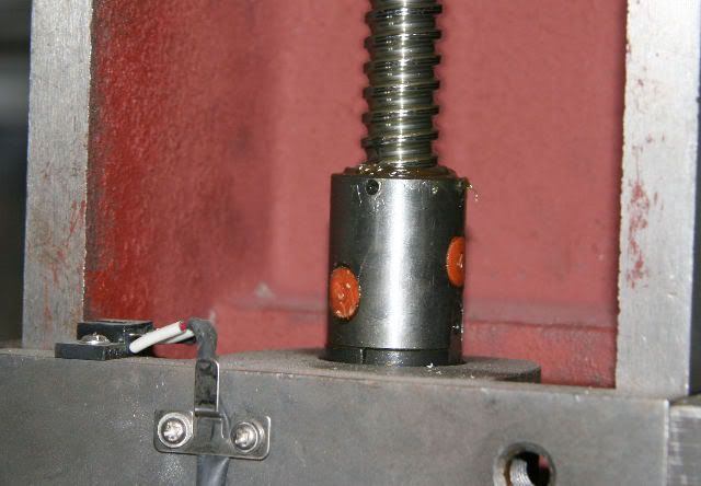
I've got the back cover off and I can manually twist the leadscrew and can see that the backlash appears to be in the coupler. There is no pressure (spins freely) when between where it tries to push the head up or down.
I'm not sure where the adjustment on the coupler is. Is it under the two orange caps and how do I get the caps off?
-
07-11-2008, 11:38 PM #8
Registered
- Join Date
- Mar 2008
- Posts
- 3655
That is NOT the coupler, but the BALLNUT. DO NOT remove the orange caps. The coupler should be at the bottom of the lead screw, connected to the motor.
CR.
-
07-11-2008, 11:43 PM #9
Community Moderator
- Join Date
- Dec 2003
- Posts
- 24223
You have a rolled ballscrew there, if that is the only nut, no lower one, then you do not have the best kind of pre-load, the cheaper version is slightly larger balls but this only works up to a point, it cannot be adjusted or is only good for lower pre-load values.
The orange caps appear to be ball-loading apertures.
In my experience, rolled ball screw without double nut, always seem to have some backlash present.
If you see the screw turn and no up or down movement then the BL is in the nut.
Al.CNC, Mechatronics Integration and Custom Machine Design
“Logic will get you from A to B. Imagination will take you everywhere.”
Albert E.
-
07-11-2008, 11:50 PM #10
Registered
- Join Date
- Jun 2008
- Posts
- 9
CR,
Thanks. it turns out I was turning the coupler to spin the leadscrew with my fingers.
There is some slop in the coupler. I can wiggle it back and forth fraction of a turn where it is loose.
But, there must be another source of error as there is over 1/2 turn when turning the coupler where it is still in free space.
So, if I wiggle it back and forth I can see some in the coupler, but, the rest is above where the leadscrew is connected to the load. Don't know if that's the ballhead or not.
I can see the setscrews now in the couple. If I tighten up the coupler that would fix the minor backlash. There would still be a large backlash somewhere else.
Wayne
-
07-11-2008, 11:55 PM #11
Registered
- Join Date
- Mar 2008
- Posts
- 3655
There should be a nut on the UNDERSIDE of the ballnut. If this nut is loose then there will be more backlash than usual between the ballnut and the head carriage.
CR.
.5K
-
07-12-2008, 12:16 AM #12
Registered
- Join Date
- Jun 2008
- Posts
- 9
The only thing I can see is a bottom plate. I have taken out the slop on the coupler. I need to find my loctite before I put back in the second set screw and hopefully that will prevent the coupler from coming loose again.
Now for the top assembly.
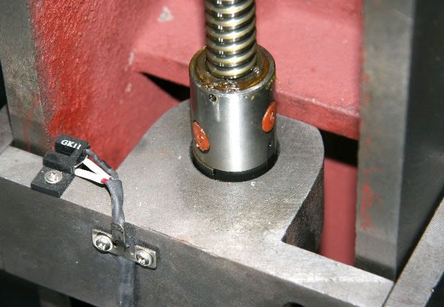
Top view:
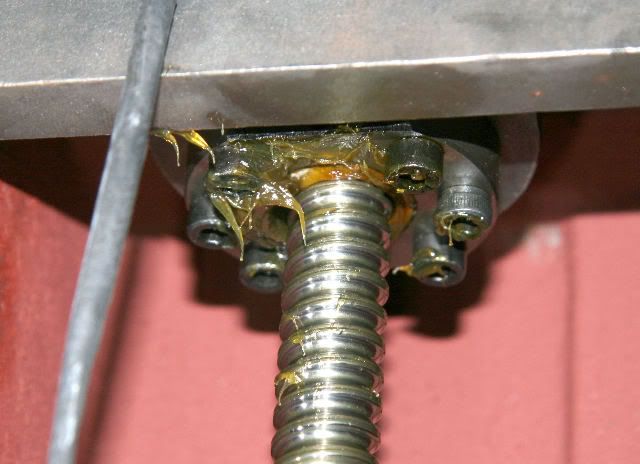
Bottom View:
I'm making progress. Thanks a bunch.
Wayne
-
07-12-2008, 12:32 AM #13
Registered
- Join Date
- Mar 2008
- Posts
- 3655
Those set screws are holding the lock nut in place. If it were possible to tighten that nut until the next set of holes lined up, then you'd be good--But I doubt if that is possible. You could at least make sure the screws are tight though.
CR.
-
07-12-2008, 12:44 AM #14
Community Moderator
- Join Date
- Dec 2003
- Posts
- 24223
One other source is the thrust bearing at the end of the ballscrew, this can also show up as actual vertical movement of the screw when under a load and the nut stay stationary, if it is loose. Originally Posted by wyc
Al.CNC, Mechatronics Integration and Custom Machine Design
“Logic will get you from A to B. Imagination will take you everywhere.”
Albert E.
-
07-12-2008, 05:02 AM #15
Registered
- Join Date
- Jun 2008
- Posts
- 9
I reassembled the unit and checked the Z backlash. It has gone down from 86 thous to 80 thous. So, the coupler has improved the backlash 6 thous.
Woohoo! ( I guess)
I'll just have to keep an eye on it and modify my quick Z move from 0.1" to 0.2" since tools coming back up barely clear the work surface and it makes me worry.
When the machine was new the Z backlash was down around 8 thous.
I don't think the backlash at the moment has any impact on the work or performance of the machine. I'm mostly cutting aluminum at the moment.
I also just opened a set of T handle allen wrenches and I didn't apply too much force putting back in the bottomside coupler allen when it went "Snap". Now I have a chunk of allen key stuck in the allen screw. I hope I don't ever have to work on that allen screw anymore.
Got them off ebay. They must be junk.
Is there a parts diagram of the machine or is there an upgrade to any parts on the Z axis?
Wayne
-
07-13-2008, 06:11 AM #16
Member
- Join Date
- Jun 2007
- Posts
- 3734
The allen key size.
You probably needed a 4.0 mm allen key. If the key is not a good tight fit get the correct key. The Syil machines use METRIC HARDWARE.
No doubt you got a 5/32" which is 3.968mm. Only a little bit under size. Buy some good quality METRIC KEYS, and don't use the 'BALL END TYPE' for getting things really tight. They only contact in ONE SPOT, and can damage the hex socket.
But once you've damaged the screw that makes it difficult.
If it is the earlier coupler with multiple straight slots then the screws tightens against flats on the stepper shaft and the ballscrew end which also should have flats. IMHO dimples would have been better than flats.
With the POWER ON so that the stepper is held from moving, jog Z using page-up/down keys until the screw is accessible.
Now gripping the ballscrew firmly but without causing it any damage turn it back and forth. You can grip with pliers and some aluminum right NEAR THE BOTTOM as the head will never go down more than 380 mm from the top without hitting the bed.
There should be NO BACKLASH.
Make sure the screws line up with the center of the flats and then tighten.
I had the same problem. You should be able to get it better than 0.001" if loose gibs are not creating subtle errors with head tilt.
After getting the coupling tightened adequately, you can check the backlash in the nut.
TURN OFF the power, temporarily LOCK the GIB with the locking lever, then attempt to turn the coupling and hence the screw. Any movement there will be backlash in the nut AND/OR the thrust bearings.
Don't forget to unlock the gib.Super X3. 3600rpm. Sheridan 6"x24" Lathe + more. Three ways to fix things: The right way, the other way, and maybe your way, which is possibly a faster wrong way.
-
09-04-2008, 06:16 AM #17
Registered
- Join Date
- Jun 2008
- Posts
- 9

I have revisted the Z axis problem on my machine and found several things.
First off the ballscrew nut assembly appears to be fine. I've taken apart the ballscrew thread detaching at at the coupler.
What I discovered is I believe a brass nut on the bottomside the bottom bearing. The end near the coupler.
This nut had completely come loose. I spun it hand tight and reassembled the unit. Now I have backlash down to 0.005" or so. That's much better, but, I believe the nut may be the preload on the ballscrew.
I have a few questions. If this is the preload screw then what should the nut be preloaded to in foot pounds.
If the nut has nothing to do with this then maybe there is somewhere else I should be looking? If so, where?
Any thoughts or ideas would be most welcome.
-
09-04-2008, 08:51 AM #18
Registered
- Join Date
- Oct 2007
- Posts
- 166
If that nut was only finger tight then there would've been very little preload on the two angular contact bearings that should be behind the washer the nut sits on. There should be shims between the bearings, so tightening it to an ever increasing level shouldn't really do much. Without the proper equipment to set and measure the preload, I just tried to get a balance of backlash vs smoothness when I had to change the factory ones on my X axis as they were really notchy. Foil shims and lots of fiddling.
For some reason the factory bearings (memory fails me exactly) are a high angle and these are expensive when you compare them to the standard low angle ones you see at most bearing suppliers. Luckily I was able to get an exact high quality equivalent pair for favours owed, otherwise I would've tried the much cheaper lower angle ones.
I can't remember my Z backlash measurement, but I will be doing it again very soon as I've got the thing apart...yet again. I don't think it was any better than what you've measured though.
-
09-04-2008, 01:50 PM #19
Registered
- Join Date
- Jan 2008
- Posts
- 458
Sure looks like a bad place for the stepper mount. Any lubricant on the ball screw will eventually migrate down to the exposed bearing on the motor.
-
09-04-2008, 04:28 PM #20
Registered
- Join Date
- Jun 2008
- Posts
- 9
I'll admit I'm not mechanically inclined. I'm all thumbs and lucky to still have all 10 digits!
That said I've been pondering this and it takes me a long time to see things clearly. Now that I've pondered over this overnight I have a couple of observations.
Even if I get the nut tightened to pre-load the ball screw nut and it takes out the backlash there is nothing to prevent the nut from working loose again in the future. Of course if this happens in the future I will hopefully remember where to tighten it up again.
But, what you can't see is the upper bearing mount has two pins in it. Great. It won't be moving. But, why? there is no pressure or load on the upper bearing mount.
Now the bottom bearing mount seems super critical if the nut needs to maintain precise pressure. If the bottom mount moves so does the nut and thus the pre-load.
How is the bottom bearing mount held in place? With two screws and the bearing mount holes are slotted allowing it to adjust. That means the bottom bearing mount can move over time since it has no pins to hold in place.
Yes, any grease will flow down the ball screw lubing the bottom bearing which is good, but, also onto the nut that shouldn't be moving. Bummer.
I wonder if this is different on the X4 machine.
Off to the hardware store to get an open ended 15mm wrench to tighten the nut up. I'll post an update if I can get rid of all the backlash.
Wayne

 Reply With Quote
Similar Threads
-
X2 Backlash Y axis
By BrassBuilder in forum Benchtop MachinesReplies: 9Last Post: 01-28-2008, 04:45 PM -
Backlash C-axis
By M-man in forum Daewoo/DoosanReplies: 1Last Post: 05-10-2007, 04:40 AM -
'Z' Axis Backlash ?
By andy_ck87028 in forum DIY CNC Router Table MachinesReplies: 7Last Post: 09-08-2006, 02:45 AM -
Z axis backlash
By maxxdog21 in forum Benchtop MachinesReplies: 2Last Post: 03-02-2005, 05:12 AM -
Z-Axis Backlash
By ger21 in forum DIY CNC Router Table MachinesReplies: 8Last Post: 05-19-2003, 02:42 AM
