


That machines come along fantastic! That's an awesome job you've done there, and to make your own spindle especially. I'm enjoying watching this build very much.
cheers, Ian
Results 181 to 200 of 3662
-
03-25-2013, 09:37 PM #181
 Member
- Join Date
- Dec 2007
- Posts
- 2134
It's rumoured that everytime someone buys a TB6560 based board, an engineer cries!
-
03-26-2013, 10:02 AM #182
Gold Member
- Join Date
- Jun 2004
- Posts
- 6618
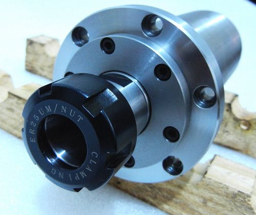
It is looking very nice. For a small one man operation, I don't think the ER collet will be too cumbersome. It any type of production setting though, time is money. ER collets take time. Quite a bit of it.
I am a big fan of R8 and TTS tooling. I have a couple ER collet holders for those too, but I find that setting the end mill height in these collets to be very difficult. Trial and error really. Tightening the collet pulls the end mill further in. For that reason, I don't use them often.
I use a butterfly impact on the drawbar and TTS tool holders.
I can change a tool by hand just as fast as an ATC and faster than most. It takes only seconds.Lee
-
03-26-2013, 05:57 PM #183
Registered

- Join Date
- Jul 2011
- Posts
- 441
Hi guys. thank all of your inputs on the spindle and tool changging issue. It seems to be a interesting point here and have many thoughts on this subject.
I decided to go with the very basic way on the spindle system because I know I couldn't get both of the accuracy and convienience with economic spindle system. Considering most personal appliactions don't repeat cutting many times or need rapid batch machining, I think it should be best to keep the accuracy as the key point and basic configration. We know each joint point, like R8 taper to spindle hole, ER collect to R8 chuck will contribute error. so totally with a R8 tool holder with ER collect, the last rotate error at the tool end will be around 0.02mm. So I think wiout the middle joint taper, the ER spindle will have less than 0.01mm error. I agree that changging the ER collect and tools frequently take long time, but... if don't repeat this whole day, it should be okey at least, it's some same cumbersome as doing with a manual R8 spindle system---but better accuracy.
I agree with Handlewanker, many nuts for every ER collect is helpful to save time and don't cost much. And even the batch milling works mostly don't need upto 6pcs tools. And I agree, repeating one process with one tool for batch machining is the best way to save time. but the key point is to locating the workpiece exactly as last turn.
About the power tool changging system, I think we don't need to talk about the BT series for industrial here. Actually I think ISO15 or ISO20 series spindle system is the best for such small size benchtop CNC machines with power draw bar or even with ATC.---but they are not any cheap thing and I think the ISO tooling system will be even more expensive because not common as BT ones.
I understand Tormach tooling system very well and agree it's a very good design: easy updating, fast changing and economic. It should have similiar accuracy as common manual R8 system. with the big round top touching the spindle nose, it can set the tool hight repeatable. The potentional problem of TTS is that the rigidity is not as good as BT or ISO ones. Of course, ER collect body can be designed to be similiar to TTS with power drawbar. But the problem is that the ER collect is too short to hold a tool holder( I guess it's another ER tool holder with parallel shank). So I think the whole spindlle holding torque maybe weak and also maybe easy to damage once tool collision happen. I have some better thinking similar to BT series, but very initial now. I think I will do this some day in future if the market is strong
The key point actually is the maket volumn. We always can do very good design and make a perfect part. If only several person need this, it will be expensive, but if 1000 persons need this, it will be economic.www.skyfirecnc.com
Email: [email protected]; Skype: skyfirecnc
-
03-26-2013, 06:42 PM #184
Registered
- Join Date
- Jul 2011
- Posts
- 441
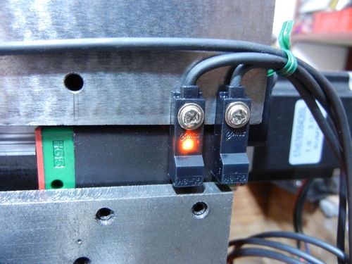
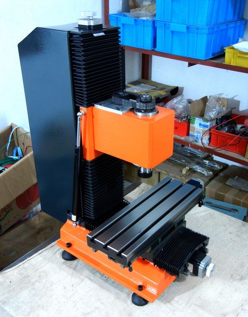
I tested the home and limit senser switch today. they work well. This is the best choice for very long life, IP67 protection grade. I set them on all three axises.
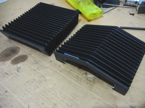
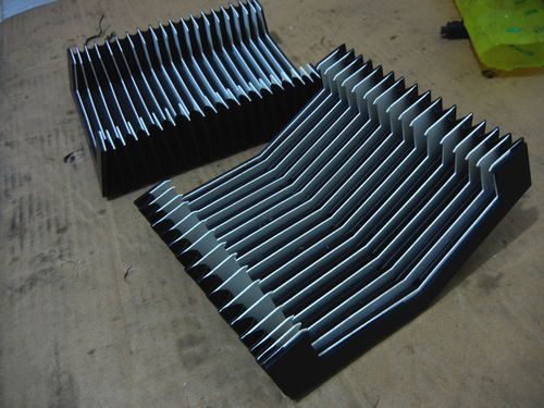
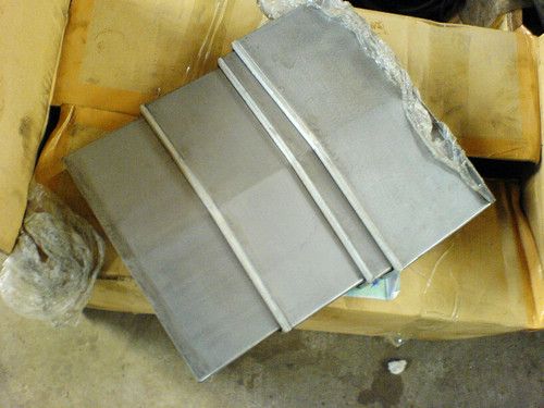
I also received the special ordered axis covers. They look very nice as my former orther ordering. I totally designed as industrial level and asked for best materials. The Y axis cover is of umbrella type as big industrial machines I'm sure it will make the machine cool..
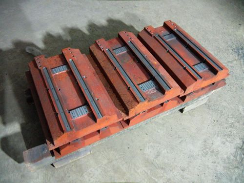
I'm also working on the batch production arrangment now.. so maybe take order very soon. parts are under machining and begining long term part storing now.
 www.skyfirecnc.com
Email: [email protected]; Skype: skyfirecnc
-
03-27-2013, 02:38 AM #185
Member
- Join Date
- Sep 2006
- Posts
- 6463
Wow, awesome set-up.....I love the logistical approach to the future sales potential as oppposed to just making/selling if/when an order arrives.......lots of hard sell for the design needed to put it into the class it deserves and highlight the unique features.
Ian.
-
03-27-2013, 03:06 AM #186
Gold Member
- Join Date
- Jun 2004
- Posts
- 6618
I agree. As a starter machine, it ain't bad at all. I'd even say in small production runs, it would do very well. Keep it up. Looking great so far.
Lee
-
03-28-2013, 06:43 PM #187
Registered
- Join Date
- Jul 2011
- Posts
- 441
Hi guys. Thank all of you support my thread so much. That drive me must make sure won't let you guys feel sorry at last
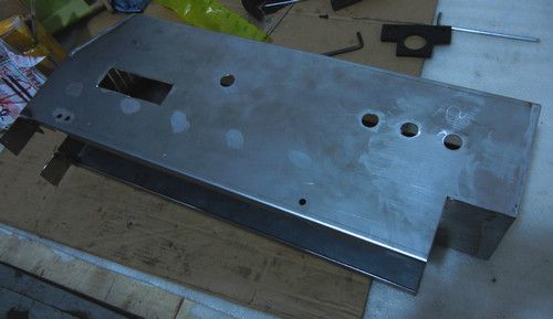
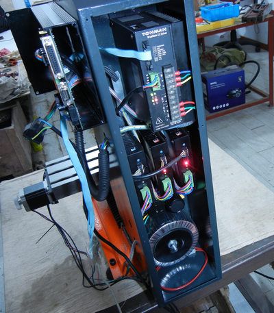
Finally I get the last decision of the simple electric box design and made the first one. I think I'm satisfied for this design. This cost me much time to make the most reasonable arrangement considerting:
1. most reasonable arrangement for wiring.
2. supporting upgradeable 4th axis driver.
3. can fit in both BLDC driver or VFD driver for user selection.
4. enough power capacity of transformer DC supply system.
5. best cooling air flow design.
6. minimum EMI possible.
7. as compact size as possible and beautiful appearance.
8. full protection of all axis totally covered.
9. compatible of other controller board attached or updated by users. I'm sure this will make some fun on the machine.
10. a small control panel with main power switch, ESTOP button, LEDs, and AXIS FREE buttons.
Some features above actually have many contridiction points. so... just many balance works.
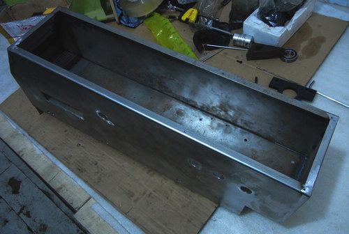
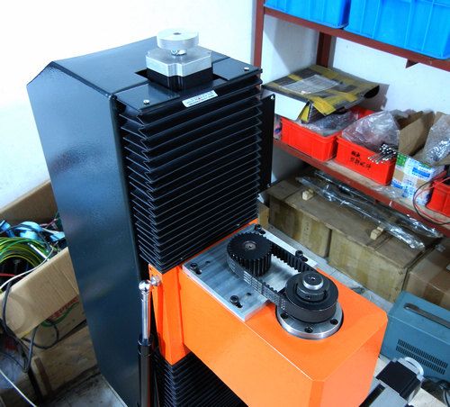
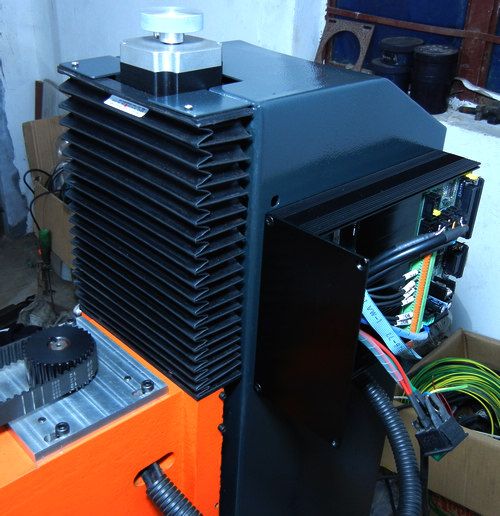
here are the pictures of axis cover attached and electric box and part arranging. Not completed yet but I think the whole machine is very near to completed for final test now.

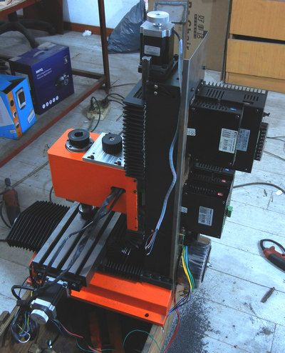


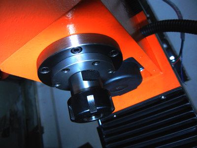
and a picture of trying to install the spindle unit to the head.
 www.skyfirecnc.com
Email: [email protected]; Skype: skyfirecnc
-
03-28-2013, 07:21 PM #188
Registered
- Join Date
- Mar 2013
- Posts
- 124
Very nice work.
Why spend so much time on the control box? I can't imagine that couldn't have been done with just tabbing and rivets/nuts. Seems like that would be a better option for any future production of these.
-
03-28-2013, 07:53 PM #189
Registered
- Join Date
- Jul 2011
- Posts
- 441
Hi Topdecking. Thank you for your inputs. Maybe it seems not complex things after all parts settled now. You can just pile up all parts any way you want and connect them to workable. But from my experience before, electric system always have some issues can't be seen by eyes. For example, we must aware that the VFD itself and motor phase lines will generate big EMI around that could crosstalk to stepper pulse signals may cause stepper motor shake or lose step. So we must try to make it as far as possible to controller board and signal wires. and avoid parallel to any other signal wires. And we'd better isolated with shield to controller. This is only one of the considerations of part arrangement. Originally Posted by Topdecking

I didn't just attached a simple electric box to the machine because I tried to make the machine whole as something of art. So I will try to avoid show many screws or mounting marks on the surface. Many other detail considerations I can't list here one by one... Just give the last best result from my capacity. Maybe it will be easier to understand if you take it as a car.
Cheers~www.skyfirecnc.com
Email: [email protected]; Skype: skyfirecnc
-
03-29-2013, 03:26 AM #190
Member
- Join Date
- Sep 2006
- Posts
- 6463
Hi, that's one big mother of a toroid transformer in photo #1.....one question.....with the toroid transformer at the bottom all the heat it generates will add to and increase the heat in the rest of the circuitry above it as heat rises........would it be better to have the toroid tarnsformer at the top with a large fan at the bottom to direct cooling air first over the more sensitive electronics and finally to the tooid transformer and venting out of the top?
Those way covers are really eye catching, but how practical are they when they compress with the slots filled with chips?
I quite agree that the electronics enclosure is an area that does need total shielding from ingress of coolant, atmospherics and fine dust, and the fully welded seams are what it needs, however the cover or door has a seal that really needs to be 100% tight or the welded seams of the casing are overkill and could, as has been said, be screwed or riveted......I prefer the welded seams as this reduces the possible ingress of contaminants.
In the last photo of the spindle end you show the end of the motor behind the spindle sticking out of the casting bottom with gaps round the sides......(the motor is round and the cavity is square).....is this practical as that is a big swarf gathering area directly behind the cutter?
I would have thought that it would have been better to have the bottom of the head casting behind the spindle totally enclosed at the bottom mainly to give clearance behind the overhang of the spindle and also to keep that area "muck" free.
If the end of the motor, sticking out of the head casting, is designed to give cooiling to the motor, it will also get lots of "muck" too......bad point in my estimation.
Ian.
-
03-29-2013, 03:33 AM #191
Member
- Join Date
- Sep 2006
- Posts
- 6463
Hi, just looked at the photos again.......there is no door......the casing is a total enclosure round the column.....hope the seal is good.
Ian.
-
03-29-2013, 05:47 AM #192
Registered
- Join Date
- Jul 2011
- Posts
- 441
Hi man, Thank you for the questions of all the details. here are my answers to them: Originally Posted by handlewanker
1. mounting the big transformer at the bottom of the casing is some best choice to lower the center of gravity to make machine more stable. I understand your worrring about the heat issue. The point is to ensure the transformer never get "hot". I choosed the toroid type transformer instead of the traditional square one because it has much better efficiency to lower the heat generation. Another issue is to make sure the transformer have enough power capacity to be just "warm" instead of "hot" even under heavy duty. If any transformer will get "hot" under normal working conditions, the only excause is that made of bad material or short of power efficiency. And at last, the current pictures didn't show that I actually arranged a big cooling fan just mount on the top of the tranformer and the rectifier board.
The casing only has a air entrance at the bottom by a cooling fan with air filter, and a louver at the top. other positions are totally sealed by welding. there is no way to allow chips or dust come into the casing. So I did consider this casing from industrial level.
2. About the axis covers, I think you mean the ones on the Y axis travel. Yes it will gather chips there, and that's why I designed the covers to be unbrella shape to help chips fall. But the covers will still need manual cleaning after cutting works done. The only way we solve this perfectly is to using the steel covers like this one I used on big machines. But it's much more expensive and will cause the whole machine structure design complex and losing the economic features.
3. as to the motor sticking out of the spindle box, I had noticed this when I first tried to mount it in. You ar quite right that this part should be shielded from chips. So I leave the screw holes there to add a cover later. Just have not done it yet. Actually I have not finished the cover sealing works yet. there will be some small stainless cover parts to be added to make the machine completly sealed.
chees man!~ Thanks again for your questions here.www.skyfirecnc.com
Email: [email protected]; Skype: skyfirecnc
-
03-29-2013, 02:13 PM #193
Registered
- Join Date
- Apr 2006
- Posts
- 169
:banana::banana::banana::wee::wee::wee:
-
03-29-2013, 02:55 PM #194
Member
- Join Date
- Sep 2006
- Posts
- 6463
Yes, I forgot the balance point of view....the Toroid is a biggie and could cause some inertia vibration resonance problems if at the top.
That's a good plan to have a large Toroid that barely gets warm.....most manufacturers would go for a smaller unit to cut cost and hope the heat is not a problem.
The way covers look so professional and really enhance the appearance of the machine.....colour matches the paint work with good contrast.
This build has been an eye opener as to the lengths you have to go to, to achieve something out of the ordinary....not just a simple conversion of a manual mill and a slap on a few ball screws and a stepper or two type of job.
Whatever the price I think it will be the real deal.....now to find something to make....LOL.
I would imagine that if the design of the 4th axis unit is anything like the spindle build it will be awesome.
I've come to the conclusion that even if you don't need/want to make money with a machine like this, just owning it to "mess" about with in your spare time would be most satisfying, as the build would not need to have any upgrading done to really output the work if the need arises......once you have the means the incentive to be innovative is catered for, and engineers just love to see the wheels go round.
I'm getting worried at all the "goodies" being added to the build....... starting to look expensive ......hope you're keeping count of the cost...LOL.
Ian.
-
03-29-2013, 08:20 PM #195
Registered
- Join Date
- Jul 2011
- Posts
- 441
Hi man. Thank you for more comments here~ Originally Posted by handlewanker
I really don't like the cut cost way of low quality and using any part not enough specifications like a smaller power transformer even it's not obvious to see and you will not know before some real damage happens. I think that's something small but will destroy all other good works. So I will insist to use good parts on this machine even it will cause some cost rising. But I will still do my best to control the total price to the aim of under $4000. High quality VS reasonable price is my target to make the machine most valuable to customers own it. And I really don't want to generate headache post sale problems with any bad parts. So...maybe some more cost to me, but actually be good to both of customers and myself.
And I certainly will develop a 4th axis part next to make the machine have update possiblity. I hope the machine can have some good market so I can keep to provide more and more update devices to improve the value of the machine. I do take this project seriously now to be a real deal.. This is the only way to make sure it's worth to have
I will give the machine all of the "goodies" possible to make it a good "base" to handle real works or having fun. There are also some funny things can be done on it like upgrating the controler to higher level. I have consdiered the upgradable convience on the control system design.www.skyfirecnc.com
Email: [email protected]; Skype: skyfirecnc
-
03-29-2013, 09:12 PM #196
Registered
- Join Date
- Jul 2011
- Posts
- 441
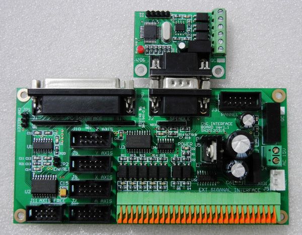
I think I should post the controller I will use on this machine now. This controller board is my personal design and finished at the end of last year. Basically it's a traditional controller just take the PC parallel port to support MACH series software. But I have tried to make it as good as it can be. The features are as following:
1. 15V AC power input. the board contains rectifier on board and a linear regulator of LM7812 to provide the stable 12V DC voltage.
2. PPTC resettable fuse on board for short cut protection.
3. on board DC/DC converter to provide 5V logic power and isolated to external circuit.
4. 4 axis driver support and PWM/direction spindle drive output
5. charge pump enable signal support for MACH software. All signal outputs will be shut down without CHP pump signal (but a jumper on board can disable this function and give the CHP signal chanel to a secondary relay control)
6. one or two(disable CHP function) relay control out put
7. all IO signals are buffered to make sure signals to be enough 5V TTL and enough driving current capacity for motor driving. This is especially useful to laptop because it's parallel output is 3.3V. some times may cause mulfunction.
8. all external input signals like HOMEs and limits, and all relay control output signals are isolated by photo coupllers to make sure controller work stable.
9. AXIS FREE function support to allow free every stepper motor so can rotate the hand wheels any time(useful to any manual works like setting tools)
10. necessory status LED indicate outputs including MACH software control enable(for Charge pump signal), spindle error, stepper driver error, travel over range, master alarm( any error occure or emergency button pushed) I'm making another small panel PCB then to support these features.
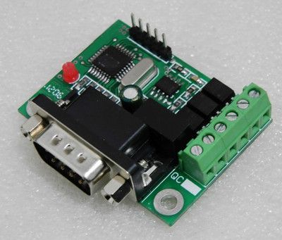
11. another small interface board that can convert the PWM/DIRECTION spindle control signals to traditional standard 0-10V VFD control signals.
So totally I designed this controller board reasonable and high standard for basic 4 axis drive system and providing as many features as possible. It consdiered much about EMI issues so many isolating methords used on it including the power suppy circuit and signal IO. It should be enough for most users. And can also be connected to any other standard MODBUS based controller board that generates high frequence pulse for SERVOs or high microstep driving(my drivers in former picture support up to 256 microstep).
here is the picture of the controller:

the PWM-VFD signal convertor:
two part connected:
hum....please make sure to ignore my electric welding and test table in a mess.
 www.skyfirecnc.com
Email: [email protected]; Skype: skyfirecnc
-
03-31-2013, 08:08 PM #197
Registered
- Join Date
- Jul 2011
- Posts
- 441
Hi guys. I have many updates now. Just finish many works today.
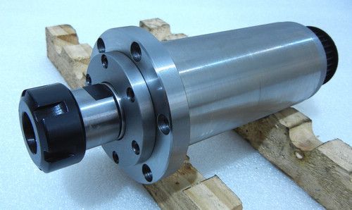
1. I have the small dimentions of the spindle unit fixed and completed the whole spindle unit assembling now. It rotates very smooth and I make it under grinding-in process with the spindle motor connected. I will measure the spindle error after this process and report here.
here is the spindle unit. seems satisfied to me


2. I have painted the electric casing with the same dark gray paint and mounted to the machine body formally.Just maching well.. And then connected the Z axis upper soft cover to the casing. The Z motor stick out of the casing for heat dissipation and easy to rotate the hand wheel.

3. All electric parts in casing are installed now(except the optional 4th axis driver) and wires connected also. Initial power on tests is no problem. All motors are succefully power on and manual tested for hours.
Here is the electric casing inside. Wire works is clean

The wires will be last settled after all other works done before closing the electric case. The cooling fan is not installed yet.
4. the attched controller box: This is a seperate part attached to the main electric case. This is an important part have many considerations here:
1. The controller board is best shielded in this isolated Aluminium box to make sure it works stable.
2. The Aluminium box is more than very nice appreciated. It has big capacity for any other controller board to update or add-in( USB controller or what ever). It has two 140mm wide PCB slots and just fit my current controller board in.
3. It's easy to open and disassemble like following picture and do any small works on controller installation and make holes on panels for ports or switches, LEDs etc.
4. The front panel will be the operation panel with main power switch, emergency button, indicators, switches. And I will praint the lables etc on it.

So.. until now, my building is very near to finish now. just some small works of worktable covers, small steel axis covers and soft cover brackets. And some electric connecting, cable tubes etc. And for the control panel.. I'm waiting for another small PCB arrive now..www.skyfirecnc.com
Email: [email protected]; Skype: skyfirecnc
-
04-02-2013, 10:28 AM #198
Member
- Join Date
- Sep 2006
- Posts
- 6463
The moment of truth....what are you going to call it?
I would have to say that EVEN if it did not get switched on it would still look very impressive just standing in the workshop to impress your mates with......it's almost a shame to make the paintwork dirty with coolant and swarf.
Is there going to be an enclosure too?....you did say that the build was almost finished.
Ian.
-
04-02-2013, 11:46 AM #199
Registered
- Join Date
- Jul 2011
- Posts
- 441
Hi my friend, Thank you for your so high praise:cheers Originally Posted by handlewanker
Yes, actually I designed the full enclosure even before this simaple electric case.. A sample is been made now too, but not finished welding by now.. The enclosure intigrated with a electric box on it. so don't need the current one at all. I developed this current simple electric casing because you guys suggest some compact size for shipping issue.. Maybe this is the best way for many customers. But a full enclosure should be easy to build and to added on the current machine, just some screwing works to the electric casing now.
The machine building is near to finishing now. just some wiring works and last tests to do. maybe mostly finish in several days. and then some commercial works like a trad mark design, a formal control pannel with prints, and some formal operation labels, manual works etc. ..
I will show the fnishing pictures and some test pictures, videos very soon.. I'm gathering some work materials for testing now.
www.skyfirecnc.com
Email: [email protected]; Skype: skyfirecnc
-
04-02-2013, 09:48 PM #200
Registered
- Join Date
- Aug 2008
- Posts
- 8
very good work skyfire, i started reading this post of yours a year or so ago, and then you went quite for a while. im so glad you came back and have now nearly finished this machine, i've thoroughly enjoyed reading its progress.
your attention to quality and detail is superb, and your posts have been very informative, i've learnt a lot from it.
i wish you the best of luck in selling this machine to many customers in the future, im sure you will be successful in doing so. i would love to buy one myself, however i plan to build my own!
how much are you planning on selling these for anyway?

Similar Threads
-
Show us your machine stands
By OHLEMANNR in forum Benchtop MachinesReplies: 7Last Post: 05-05-2013, 03:19 AM -
a machine design (pics) from beginning to end
By blurrycustoms in forum Vertical Mill, Lathe Project LogReplies: 42Last Post: 04-25-2013, 02:36 AM -
dry build or glue from the beginning?
By Ezra in forum Joes CNC Model 2006Replies: 2Last Post: 10-29-2010, 04:44 AM -
Newcastle: Beginning of build plan
By pippin88 in forum Australia, New Zealand Club HouseReplies: 7Last Post: 09-16-2010, 10:22 AM -
Beginning to build my Z-axis.
By zonk2 in forum DIY CNC Router Table MachinesReplies: 0Last Post: 12-23-2008, 06:17 AM
