


Ok, so I really didn't pay much attention to the placement of the pancake cylinder in my first design and had to move it forward a bit to clear my motor.
I didn't have a chance to make my first design, so nothing lost there.
On another note, Thanks again Hoss for steering me in the right direction on info to reuse the stock Tach. And Michael (mhackney) for posting the info on how to make it happen {post #478 on his G0704 build thread}. But this also lead to a bit of sadness. Turns out my KBBM-125 was set somewhere around 85 VDC, and I was only getting in the ball park of 4500 rpms. when I crank it to about 120 VDC, it gets to about 6500 rpms. Problem is My AC bearings on the spindle don't seem to like that speed and get HOT! The upper quill bearings are getting very Hot as well. They are Deep groove bearings and the bigger one is rated for 7800 rpms iirc. I ended up turning the KBBM-125 down to about 92.0 VDC to get around 5000 rpms.
Not really happy about the heat Issues I'm having. Hopefully someone can suggest somethings to help trouble shot it. It maybe time to get a temp gun and hand held tach?
I'm using a 7007B (9500 rpm limit) and 7005B (13000 rpm limit) for the spindle. The upper quill has a 6209ZZE (7800 rpm limit) and 6007ZZE (12000 rpm Limit). All from VXB.com, using kluber to grease the AC's. The retainers were turned to they stopped and then given a very light nudge tighter. Maybe I need to go to just where it stops?
I'm using the stock tach, currently powered by a 9 volt battery and I'm holding the pick up sensor by hand. I know.... hokey!
Help me Obi' Hoss Kenobi, your My only hope!
Andrew
Thread: Andrew's G07040 build
Results 21 to 40 of 241
-
08-21-2013, 05:41 PM #21
 Registered
- Join Date
- Sep 2012
- Posts
- 323
PDB Idea! .... 1.1 And spindle\upper Quill heat issues
-
08-21-2013, 06:26 PM #22
Registered
- Join Date
- Mar 2013
- Posts
- 124
Question, I understand now about keeping the load off the spindle bearings. Makes perfect sense.
However... How is the drawbar supposed to be able to spin freely in these designs? Does the entire stack of washers + drawbar spin and is there a bearing then in the "lifting plate" below the belvilles?
-
08-21-2013, 06:53 PM #23
Registered
- Join Date
- Sep 2012
- Posts
- 323
There will be a plate that will sit against the risers for the motor mount. It will have clearance around the spindle and will have a .050~.100" gap between a "top hat" and the plate. The disc springs will sit above the top hat. and there will be a gap above the drawbar so the lever doesn't touch. The air cylinder fires and pushes the lever, which in turn also pulls up on the plate and compresses the disc springs. Thats also why the shoulder bolts are used with a spring to keep the plate down when the spindle is turning. Originally Posted by Topdecking

My designs don't show most of that, I was just using it mostly to figure out spacing and how much movement I would get at the spindle end of the lever. This should give me 4X the cylinders pressure and half its travel at the spindle end of the lever
Hope that make a little sence
Andrew
-
08-21-2013, 07:08 PM #24
Gold Member
- Join Date
- Feb 2006
- Posts
- 7063
If the contact points of the levers are really as-drawn, I think you're going to find a huge amount of force lost to friction, followed by very rapid wear at the pressure points. You'd be much better off using ball-bearings as roller followers. The same may be necessary at the pivot points. Plus, as-drawn, you will be generating some really huge side-loads on the air cylinder piston, and several of the pivot points.
Regards,
Ray L.
-
08-21-2013, 07:32 PM #25
Registered
- Join Date
- Sep 2012
- Posts
- 323
Really haven't figured out the be best way to transfer the force from the cylinder to the lever yet. Thats one of the reasons I wanted to post it up here, so others to give me pointers to make it happen. Originally Posted by SCzEngrgGroup
A little more info on the "using ball-bearings as roller followers"? As a buddy in tech school would say, "assume I know nothing!" . He really liked to give the shop teachers a hard time.
Thanks
Andrew
-
08-21-2013, 07:54 PM #26
Member
- Join Date
- Apr 2006
- Posts
- 8159
PM sent buddy.
Hosshttp://www.hossmachine.info - Gosh, you've... really got some nice toys here. - Roy Batty -- http://www.g0704.com - http://www.bf20.com - http://www.g0602.com
-
08-21-2013, 10:42 PM #27
Gold Member
- Join Date
- Feb 2006
- Posts
- 7063
Where your drawing has an arm with a radiused end acting as a cam, replace the radiused end with a ball bearing, so the contact with the other arm is the outer race of the bearing, and you rolling, rather than sliding, contact. If you slot the end of the arm so the bearing fits into the slot, then drill a cross-hole and put a bolt through the cross hole, and the ID of the bearing, to hold the bearing in place. This will GREATLY reduce friction and wear. You'll still have very high pressures at the contact point, so you'll likely need to put a hardened surface there. Originally Posted by Wiggles84
You'll have to provide a radial support for the air cylinder shaft, as they are not designed to take high radial loads (which will also destroy the shaft seals). A bronze bushing is probably your best bet there. You can also allow the cylinder to pivot, so the force always stays aligned to the cylinder axis.
Regards,
Ray L.
-
08-22-2013, 08:58 AM #28
Registered
- Join Date
- Sep 2012
- Posts
- 323
The end has a radius to clear the lower arm. there will be a connecting arm between the upper and lower lever arms on the left side of my drawing (yet another thing I didn't put in the drawing (chair) ). Originally Posted by SCzEngrgGroup
So cylinder extends and pushes the top lever down, pivots on the second hole from the left. left side goes up and force is doubled. left side of top lever pulls up on left side of bottom lever. bottom lever pivots on the second hole from the left and force is again doubled to the right side of the lower lever.
I ended up ordering some different disc springs that are about 2000 lbs of force at load and 2950 lbs at flat. So I'll only really need 3X the power of the cylinder to compress them flat.

If I misunderstood what you were trying to tell, please tell me and feel free to (nuts) .
Side Note:
I ordered a hand held tach and temp gun from Ebay and should have them by Monday. We'll see, Said ships from the US but is coming via DHL. Which I thought was from over seas?
Andrew
-
08-22-2013, 03:22 PM #29
Registered
- Join Date
- Sep 2012
- Posts
- 323
Hoss, what gives? You no likey PMs?
response to PM:
I've replaced the two bearings on the upper quill (#206 in the book) with deep groove bearings from vxb. And the spindle has never seen chips. But I was thinking of pulling it apart, cleaning everything out and work on the fit of the bearing a little. They were tighter than a hand press but I did not need to use any kind of press or BFH to get them on. just a 1"od by 2' long piece of brass and tubes it even out the force when tapping them down. the bearings on the upper quill were tight to. could this be causing my heat issues? I really don't deal with bearing in my day to day at work, so this kinda new to me.
I have a temp gun and tach on the way.
thanks,
Andrew
-
08-22-2013, 03:37 PM #30
Member
- Join Date
- Apr 2006
- Posts
- 8159
another pm sent, should work now.

Hosshttp://www.hossmachine.info - Gosh, you've... really got some nice toys here. - Roy Batty -- http://www.g0704.com - http://www.bf20.com - http://www.g0602.com
-
08-23-2013, 04:14 PM #31
Registered
- Join Date
- Sep 2012
- Posts
- 323
Ok, so I:
*took the spindle apart
*took some 400 grit to the upper area where the bearing goes
*cleaned the bearings off
*re-greased the bearings
*I could not get the lower bearing off of the spindle
Once I got everything put together, setting the preload was a PITA! I ended up screwing the top nut to the point where it just touched the upper bearing. Had to hold the nut in place with a adjustable spanner wrench to tighten the two screws.
I checked the pre load by holding the spindle and spining quill housing by hand. Tightened to the point where it still spun freely and still coasted to a stop. I figured that if it came to sudden stop, it was to much pre-load.
I have to say it is a little loader than before, but I also didn't re-grease the spline of the spindle before putting it back in the head. Heat is much better on the spindle end. I can run at 6000 rpms and it is not as hot as before when I was running at about 4500 rpms. but the bearing at the top of the head is still getting about as hot as it was before. Still a 1500 rpm improvement... not bad.
Anyone ever try to "water cool" the head on one of these machines?")
Andrew
-
08-30-2013, 08:25 PM #32
Registered
- Join Date
- Sep 2012
- Posts
- 323
Well my heat problems seem to gone :banana: . I think it was a combo of to much preload on the spindle bearings and the belt drive being to tight. can go full out @ 7100 RPMs with the 1:1 pulley setup. spindle stays under 90o F. Top bearing under 100o. the side of the head gets the hottest @ around 106o.
So I decided to start working on the rest of the machine for a bit so I fell like its getting somewhere.
Machined the base:
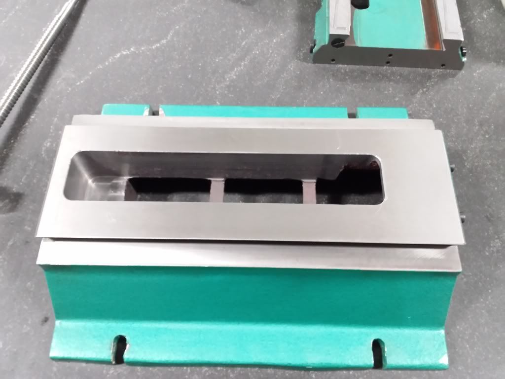

Put the ball nut clearance in the saddle and cut the oil groove:


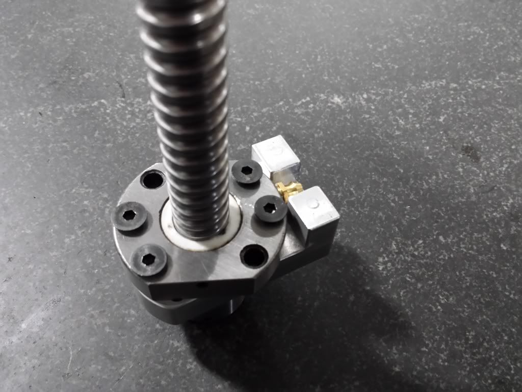
Made the ball nut for the Y axis and made a few changes, I rotated the bolt hole pattern by 22.5o to get the oil fitting to face straight up through ball nut mount.I think it will still clear just fine in the base with out clearing the ball nut.
now I just need to get a fitting that has the reach (not much out there with a m6x1 thread).

Then I put the base, saddle and y ball screw\nut together for a quick mock up

Now I kinda feel like some progress as been made!
Andrew
-
08-30-2013, 09:34 PM #33
Registered
- Join Date
- Mar 2011
- Posts
- 96
I was just in the process of redesigning my y-axis ballnut mount to do exactly what you did. I want the oil port to point straight up. Please keep us informed if you have any clearance issues.
-Kevin
-
08-30-2013, 10:06 PM #34
Registered
- Join Date
- Sep 2012
- Posts
- 323
It maybe some time before I get to the assembly stage on the mill You maybe telling me if there's any clearance issues with the ball nut! For the fitting I was thinking either this from msc and spinning an m6x1 die on it. Or this from mcmaster using a set screw with a hole thru to connect the two. Originally Posted by Mystichrome
Thoughts?
How is everyone else oiling there china Z ball nuts?
Andrew
-
08-31-2013, 02:59 PM #35
- Join Date
- Feb 2013
- Posts
- 38
That's a really good idea on the y nut, nice job!
take care
Kevin
-
08-31-2013, 04:22 PM #36
Registered
- Join Date
- Sep 2012
- Posts
- 323
I'm kinda surprised that I haven't seen this done before. There's really no other way to position the fitting and use it without clearing out the base more or losing one of the spots for the two screws to clamp the nut mount to the saddle. Thought about just putting a hole from the top of the mount and let it drip into the opening. Messy was all I could think of. Originally Posted by Kevinj308
Andrew
-
10-27-2013, 12:42 PM #37
Registered
- Join Date
- Sep 2012
- Posts
- 323
Made some more (small) progress on the conversion.
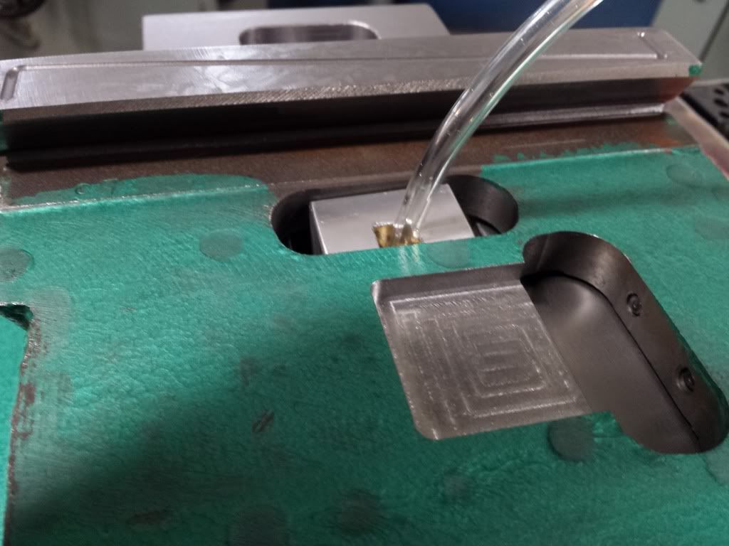
got one of the push to connect fittings on the Y ball nut


But then the table had to be cleared for the fitting

Andrew
-
01-29-2014, 04:16 PM #38
Registered
- Join Date
- Sep 2012
- Posts
- 323
Update.......Need some help!
Made some progress on the conversion. Got the column and head spacer made, Z ball nut mount and put in the oil grooves in the Z carriage. Also made the stepper risers. Next big step will be getting the oiling system plumbed, once I figure out how I'm going to do it!
So based on where I'm at with the conversion (and had a balance in my paypal account) I ordered the steppers (570 OZ), 3 axis driver\B.O.B (MX3660) 48V PSU, estop and limit\home switches.
I got the motors to move under mach 3 control and then moved on the figuring out the limit switches. I bought the A60 inductive proximity switch from cnc4pc. but I'm not sure how get it working with the mx3660. I can get the switch to power up by putting the black wire into input1 and the blue wire into the GND next to it, brown not hooked up at all. The switch seems to power up fine and the led on it goes off if I put metal in front of it. but I'm either getting a constant signal in mach are not one at all depending on the active low setting. Port (1) and pin (10) looks right in the settings. Anyone have an idea?
This was just my first crack at setting up mach so I may figure it out later when I get a chance to play some more, when the kids head over to grandmas house :cheers:
Andrew
-
01-29-2014, 08:20 PM #39
Registered
- Join Date
- Sep 2012
- Posts
- 323
so now I'm really stumped..... but first I have to correct my last post. I did not state the wire connection on the A60 right. brown into input 1 and black into GND and sensor powers up. but I am not getting anything on the computer for for a signal.
I put a multimeter on input 1 & GND and got 12V. I got a 5V PSU sourced from some forgotten device and powered the A60 with it. still not getting a siginal on pin 10 for input in mach.
I'm about ready to start (nuts) !
Can someone please chime in and help get this figured out?
Edit:
Forgot to say that I am running the demo of mach 3. could that be causing the issue?
Andrew
-
01-29-2014, 08:55 PM #40
Member
- Join Date
- Apr 2006
- Posts
- 8159
According to the pdf, black goes to the input and blue to ground, brown to 5v.
You might have to change active low for the input in ports and pins.
Hosshttp://www.hossmachine.info - Gosh, you've... really got some nice toys here. - Roy Batty -- http://www.g0704.com - http://www.bf20.com - http://www.g0602.com


 Reply With Quote


Similar Threads
-
Andrew's G0704 CNC Conversion
By andrew2085 in forum Benchtop MachinesReplies: 12Last Post: 01-21-2013, 06:04 PM -
Mint's Build Aluminum/Steel Build thread.
By FreshMint in forum Maintenance DIY DiscussionReplies: 0Last Post: 10-31-2011, 04:18 AM -
Newbie - To build or not to build Router/Plasma Table
By dfranks in forum Waterjet General TopicsReplies: 10Last Post: 04-08-2011, 05:16 AM
