


Hi all,
I think this is the right forum for this question. I have a woodworking machine, a shaper, which I use to run full length 1 3/8" delrin rod through. I cut a flat on it, then run in again to cut a small groove on the other side. Then I bring them to the shop and finish the machining on machine tools.
It's an Italian machine set up for US 220-240 single phase. It has a separate power feed, and when running the stock, the capacitor in the power feed shorted out. Since the machine itself was coming up to rpm very slowly, I checked the capacitors in the elecrical panel before ordering the power feed capacitor and found both capacitors in the shaper to be in bad shape.
So I bought new ones at the same voltages and uF rating.
After installing them, everything worked for a short while, then the main machine stopped at about the time I smelled the motor burning. The power feed continues to operate fine.
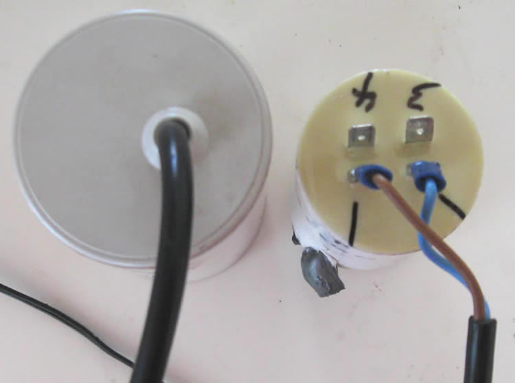
Here are some pictures of the original weird capacitor setup, for your viewing enjoyment. The one on the left, by itself, I replaced in the power feed, which still works fine. Before I ordered the replacement, I checked the ones in the main machine - which was starting off very sluggishly, but it did run. What I saw is that one had the huge drool of hard grey stuff, so I decided to replace the two of them as well. STUPID! I should have waited until I ran the plastic first.
The smaller one of the two that are connected has 4 separate terminals coming out of the epoxy top, and has two voltages marked on it. It says 40 uF AC 400V B then has a dotted line and under it is says 40uF 450v C. The larger one is 80uF 130/480 VAC. Motor 110/230
After cooking the motor, I discovered that the large capacitor had a cap on it after I dropped it and it popped off. This is what I found inside. The relay inside of the big one has a symbol which looks to me like a normally closed switch, then a dash, then 110v = DC. There is something to the left of the big white rectangular thing which got hot enough to cause the plastic cap to discolor and cause a bulge in the plastic case. Looks like what resistors and diodes look like - but it is mostly burried in the epoxy, so I can't see any markings. The round blue one is a capacitor - 100uF 160v.
Does anyone have an idea what this stuff does? Does it replace the centrifugal cutout switch normally found in US made single phase motors?
I am hoping the motor company can just tell me where to put the capacitors, and add a cut out switch to the motor (assuming that's what the above electronics are for) so I don't have to mess with this any more. I have never had any luck with motor companies, and wish I knew how to test the things myself. Seems like they always mess the motors up - or say they work fine when they don't.
I have no wiring diagram, no operators manual, and the machine is no longer imported into the US. Also, the motor has a brake which is working with both the manual switch, and when the "motor on" switch is activated.
Any help or suggestions would be greatly appreciated. Thank you.
Cheers,
Jim
Results 1 to 19 of 19
-
07-31-2008, 05:15 PM #1
 Registered
- Join Date
- Jun 2005
- Posts
- 37
Electronics within capacitor casing?
-
07-31-2008, 05:28 PM #2
Community Moderator
- Join Date
- Dec 2003
- Posts
- 24220
As you say, That appears to be a external automatic start winding switch.
It is done electronically, so if it fails, the start winding stays in, and also, if it is not an AC run capacitor, but an AC start type, keeping power to it cooks the Cap.
There are external current detect switches for this application, take the motor, or at least the motor details to one of your local rewind shops and they may fix you up.
Al.CNC, Mechatronics Integration and Custom Machine Design
“Logic will get you from A to B. Imagination will take you everywhere.”
Albert E.
-
07-31-2008, 05:50 PM #3
Registered
- Join Date
- Jun 2005
- Posts
- 37
Thanks Al,
So by running the motor with the new capacitors, not knowing about the hidden electronics, I cooked some part of the motor?
Is there any way for me to test the motor with a multimeter before unbolting it to make sure some windings are cooked? The motor did get quite hot, but not so as I couldn't touch it.
Thanks,
Jim
-
07-31-2008, 05:58 PM #4
Community Moderator
- Join Date
- Dec 2003
- Posts
- 24220
What you could do is first check the run winding, this should be OK, apply power to the motor with the start cap set-up disconnected, and immediately use some method of briefly turning the shaft over quickly, like a pull start on a gas motor, but have both ends free.
The motor should start in either direction and go into full rpm run.
If you succeed at this, you could connect a proper sized AC run cap. as the original was, and as soon as the motor gets up to speed (a second or so), pull one end off the cap connection.
This uses the start winding for a second and then will only use the run winding as before.
Ohmeter will not usually tell you anything but an open circuit.
Al.
 Originally Posted by jimc
 CNC, Mechatronics Integration and Custom Machine Design
“Logic will get you from A to B. Imagination will take you everywhere.”
Albert E.
-
07-31-2008, 08:03 PM #5
Community Moderator
- Join Date
- Dec 2003
- Posts
- 24220
Re-reading the thread, I realised you mentioned two caps, may be the small one that is leaking may be the only problem, the resistor in the top of the other cap may normally get hot as it is fairly high wattage. ~10w.
Did you try just replacing the leaky one with an AC run type with the same value?
Is it possible to see how the leaky one is hooked up?
Al.CNC, Mechatronics Integration and Custom Machine Design
“Logic will get you from A to B. Imagination will take you everywhere.”
Albert E.
-
07-31-2008, 10:17 PM #6
Registered
- Join Date
- Nov 2006
- Posts
- 90
Testing the motor
Howdy Jimc,
Al's idea for starting the motor is a good way to keep it working while you find a way to get it back to its former glory.
This method can also help to tell you if your start windings have developed shorted turns.
As the motor is running, check for signs of smoking/burning. If so, there is a good chance that the start windings are damaged. If not, then you have a reasonably healthy motor.
Just one more test, you'll need to check that the start windings are still isolated from the run windings. If there is a connection between them, it's off to the rewinders.
Even when the start windings are not connected to the power source, 'transformer action' will induce voltage into them. Shorted turns will draw power and convert it into smoke during operation!
Some years ago, I fixed this sort of problem by making a simple starting circuit.
It was little more than a relay and a couple of capacitors. It would provide power for the start winding, then shut off after a couple of seconds. Primitive, but effective .
.
Here's hoping you'll be up and running real soon.
Best wishes,
Steve tee.
-
08-02-2008, 06:28 AM #7
Registered
- Join Date
- Jun 2005
- Posts
- 37
Al,
I tried doing what you said this morning, but couldn’t get the motor running. So I took it to a motor shop, along with the two capacitors. The guy had never seen anything like that large capacitor, and had no idea of what it’s purpose is. Anyhow, he is going to test the motor – though I don’t fully understand how he can test it if he has no idea of what the capacitor electronics are supposed to do.
When I wrapped the smallest pulley on the motor with a rope and gave it a good spin, I did hear a click like you hear when a motor with a centrifugal switch is winding down. The biggest problem is that I don’t have any kind of wiring diagram or description of what goes on. I am totally ignorant when it comes to motors and electronics.
Probably the best thing for me to do would be just to throw out that motor and buy a new one with regular capacitors that are mounted on the motor, then figure out what to hook up where according to the manufacturer. It would be nice to use that one though, since the mounting bracket is right and it has a brake, not to mention that the pulley is on a splined shaft, and I will have to re-machine probably both the pulley and a new motor shaft since I am sure they are both metric.
But there is no sense getting it rewound just to burn it up again, since I cannot buy that special capacitor setup anywhere. What I am kind of hoping is that there is a short someplace in the panel with all the safety mechanisms and so on.
If I knew which wires going to the motor were supposed to have which voltages, that would be a huge help. If this guy can explain to me which motor wires need to be energized, to make the motor run backwards and which for forwards, I should be able to go from there if a problem exists in the panel. And if he can tell me how to hook in regular capacitors, I'll just eliminate those in the panel.
After the motor got hot and cut out I did. I took out the new 80uF one and replaced it with the old one (with all the electronics in it) and I used the new 40uF one with it. I even tried the leakey one too. But nothing but growling noise happened.Did you try just replacing the leaky one with an AC run type with the same value?
Do you mean figure out where the two wires go from the small capacitor? Or if there is some other monkey business going on inside of it too? Actually, I suppose I can do both. I can’t make any more of my clamps till I get that plastic rod machined, so I don’t have a whole lot to do, and that is the only source of income I have. One way or another, I have to get that plastic machined, and I hate to do in two weeks by other means what it will do in half an hour. But you got to do what you got to do.Is it possible to see how the leaky one is hooked up?
Steve,
Thanks for responding. By the time I read your post, the motor was already at a motor shop. Hopefully, the guy will get back to me on Monday with some kind of information. I am new to this area and do not know many people here, so I don’t know how knowledgeable this guy is.
I will let you all know what happens one way or the other.
Thanks for the help.
Cheers,
Jim
-
08-02-2008, 07:19 PM #8
Member
- Join Date
- Jun 2007
- Posts
- 3735
 The weird gadget.
The capacitor with the relay etc in it is a potential relay/capacitor
Your motor has a start and a run winding.
The low value capacitor is the run capacitor.
The high value is the start capacitor.
The high value capacitor creates some phase shift in the start winding and increases starting torque. Bigger capacitor, more torque.
Power is always supplied to he run winding (when running)
The start winding requires a capacitor is series with it to get the motor started.
Once up to speed (the AC voltage on the start winding will be about 130VAC) the capacitor needs to be disconnected.
Sometimes a small capacitor is left connected during run.
Once running the voltage on the run winding may be in the order of 230VAC.
The voltage on the winding is approximately proportional to the motor speed.
The potential relay is used instead of a centrifugal switch.
It is important that the start winding does have a capacitor of too higher value during run as this will cook the motor.
Many refrigerators use a potential relay, because it is difficult to use centrifugal switch in a sealed unit.
A potential relay has 2 terminals used to sense the voltage.
When the voltage gets to the desired level the contacts OPEN.
Some units have 2 sense connections and 2 free terminals going to the normally closed contacts, others may have one of the contacts commoned with the sense connection.
Measuring with an ohm-meter the two wires that are shorted are the normally closed contacts. If it has 3 terminals and is not marked it is a bit difficult to identify the sense connection and the common.
Put a 150w bulb in series with what you assume is the common connection and apply 110VAC to the free terminal of the bulb and the sense connection (non-shorted connection). If the relay clicks on you have found the common connection. If it buzzes you have found the contact that is supposed to be connected to the start capacitor.
If no buzzing or clicking, all is not well. Consult an expert, or get a new one. (expert or relay)
These numbers assume 110VAC operation. If you have 220V double the voltages noted.
The bulging GREY STUFF is the capacitor internals self destruction due to excessive current density in areas of the capacitor. This is because the capacitor has been operating outside it's designed temperature/current/voltage specifications.
I have seen this often with big air conditioner capacitors, and has been traced to faulty potential relays/contacts. Often the capacitor will melt before the motor. One error in selection of the capacitors is that the small run capacitor runs at much higher than the line voltage.
The dotted line on capacitor means DC voltage. The Letter is related to the design temperature/voltage/duty cycle. Often these capacitors are mounted ON the motor which gets quite hot, which in turn heats the capacitor and exceeds it's ratings.Super X3. 3600rpm. Sheridan 6"x24" Lathe + more. Three ways to fix things: The right way, the other way, and maybe your way, which is possibly a faster wrong way.
-
08-03-2008, 08:32 PM #9
Registered
- Join Date
- Jun 2005
- Posts
- 37
Thanks for all the help.
Al,
I checked out the capacitor setup, and it seems to me that the small capacitor is wired in series with wire #4, and the big capacitor (with electronics) is wired parallel with the little capacitor.
I am assuming that the relay pictured in the big capacitor cuts it out of the circuit through some kind of sensing mechanism. However, it cannot cut out the 40uF capacitor.
So, unless the start winding is supposed to have current all the time, there has to be another cutoff inside the motor.
I checked the wires going to the motor junction box. There are seven of them. A ground and six others. Of the six #5 and #6 operate the brake.
This leaves 4 to figure out.
With the starter switch forward this is what I get across the wires.
1-2 = 240vac
1-3 = 240
1-4 = 0
2-3 = 0
2-4 = 240
3-4 = 240
With the starter switch in reverse this is what I get across the wires.
1-2 = 240
1-3 = 0
1-4 = 240
2-3 = 240
2-4 = 0
3-4 = 240
So I assume that 3-4 must go to the starter winding, since they are energized in both forward and reverse.
So if Neil is right, and the 40uF cap is a run capacitor (and the 80uF with relay is for the start winding, and cuts itself out), then 2-4 would be for forward and 1-4 for reverse. And that would mean that the run windings would be getting the same as the start winding.
If the small capacitor was not intended as a run capacitor, and the motor does not have a run capacitor, then 1-3 would be for forward and 2-3 would be for reverse.
Does this make sense? If so, it seems to me that it would be easier to just use a 120uF start cap on #4 with a simple timed relay like Steve Tee suggested in case the motor switch fails.
What do you think?
Thanks again.
Cheers,
Jim
-
08-03-2008, 09:21 PM #10
Community Moderator
- Join Date
- Dec 2003
- Posts
- 24220
Deciphering the conections, it appears the the small cap is a run cap, in all the time, and the large one with the cut out is the start cap.
To reverse the motor, you simply reverse the AC to the run/start Caps/windings.
The AC is normally left as-is, i.e. non reversed for both directions on the run winding and the reverse switch just swaps the L & N on the start winding cct.
I would replace the run cap 40µf with a AC run type, I would recommend keeping this as obviously the motor is designed with this in mind.
You could try testing the start cap assembly as neil outlined, you would have to use a couple of large 120v lamps in series, unless you can get hold of a ~100ohm 20w resistor.
If the test works, the lamps (or load) should cut out within 1 sec.
Alternatively, if you hook everything up with new AC rated caps and after ~1sec after switch on, remove the 80µf start Cap connection only, this will simulate the auto cut-out feature, this will at least test the motor and confirm if it usefull to pursue it further.
I have my doubts that there is any further Centrifugal cut-out switch in the motor.
Can you energize the brake separately to make sure it is coming off?
Al.CNC, Mechatronics Integration and Custom Machine Design
“Logic will get you from A to B. Imagination will take you everywhere.”
Albert E.
-
08-04-2008, 03:37 AM #11
Member
- Join Date
- Jun 2007
- Posts
- 3735
 Run Capacitor
A run capacitor improves the torque available during run.
To do it really crudely, have a pushbutton (NO) in series with the start winding & capacitor, and when you apply power hold the button for a second or 2. If you need a run capacitor you can put it across the switch.
This way the motor will start with reduced torque even if you don't hit the switch. As Al says swapping both the connections to the start winding is how you get forward/reverse. With all wires disconnected, you should be able to measure individual windings. The one with the lower resistance is the RUN WINDING, and is directly connected to the power during operation.
I note that you are saying 240v therefore during run expect upward of 450v across the start winding.
This link might explain a few things. It is a bit slow to load, but I sugest you read it.
http://books.google.com.au/books?id=...um=4&ct=result
After looking back in my archives the letters usually mean
A 30,000 hours
B 10,000 hours
C 3000 hours
D 1000 hours
P0 is a package rating. The ones that ooze are not P0.
You definitely need 450-480 rating for the run capacitor.
PS:
I added this post because confusing answers (well meant though) were causing a basic problem to become a drawn out saga. :wave:
You are welcome.
NeilSuper X3. 3600rpm. Sheridan 6"x24" Lathe + more. Three ways to fix things: The right way, the other way, and maybe your way, which is possibly a faster wrong way.
-
08-04-2008, 04:20 PM #12
Registered
- Join Date
- Jun 2005
- Posts
- 37
Neil,
Thank you! I have spent hours on the internet tying to find either this sentence or its inverse:
"However, the run capacitor AND START WINDING STAY in the CIRCUIT"
To further insure that no confusion exists the author states:
"The RUN capacitor stays in series with the START WINDING for extra RUNNING torque.
So, it is now perfectly obvious even to me, that the "start" winding in a "Cap start, cap run" motor is also a "run winding".
For someone ignorant like myself to know that "run windings" (plural) are comprised of one "start" winding and one "run" winding, and not one "forward run winding" and one "reverse run winding", is not, I think, an obvious conclusion to draw.
Al's answer to the "forward"-"reverse" dillema had me searching again for the first sentence above. Since, if "forward" and "reverse" were the same "winding" (singular)- then were does the term "run windings (plural) come from?
From all my searching on the internet, until following your link, I still had not found one schematic, or one sentence, describing how many windings were in a motor such as mine. Nor that the "start winding" is also a "run winding".
Thankfully, the linked article also provided a simple drawing which shows wiring identical to what I have, so there is absolutely no confusion whatsoever.
Mission accomplished - with two sentences!!
Now all I need is for the motor guy to label the Start winding leads and the Run winding leads, after he (hopefully) fixes the motor. Then as an added precaution, I will check the resistance across both windings myself.
Thank you so much for the help, Al and Neil. I am very,very relieved.
What a great resource here.
PS. Neil, I just went back to that book and read the previous section, where the author says that a "Capacitor Start" motor (as opposed to mine) has two distinctly different "start" and "run" windings - and that the "start" winding itself is de-energrized totally after the motor starts. I think I should buy that book!
Cheers,
Jim
-
08-04-2008, 04:49 PM #13
Community Moderator
- Join Date
- Dec 2003
- Posts
- 24220
Jim, Glad the hear you have made sense of it at last, the term 'Windings' for one coil is a bit misleading to the uninitiated.
The fact that the start winding is also used in run with the smaller capacitor implies that there will probably be very little difference in resistance value between the start and run winding.
Resistance in an AC inductive circuit has little effect and is desirable to be as low as possible.
The inductive reactance is the working component here, and is dependent on the frequency of the AC supply, among other factors.
Is your motor guy going to come up with a replacement for the Start Cap
assembly?
If you are looking for a book on motors of all kinds including rewiring, there is one that is considered the Bible, it is Electric Motor Repair by Robert Rosenberg, It was first published in 1946!
It covers practice and theory of all manner of motors.
Al.CNC, Mechatronics Integration and Custom Machine Design
“Logic will get you from A to B. Imagination will take you everywhere.”
Albert E.
-
08-04-2008, 07:53 PM #14
Registered
- Join Date
- Jun 2005
- Posts
- 37
Thanks, Al. I'll just have to trust the motor guy.The fact that the start winding is also used in run with the smaller capacitor implies that there will probably be very little difference in resistance value between the start and run winding.
He had no idea about the electronics inside the start capacitor can. He just said to wait till he gets it apart.Is your motor guy going to come up with a replacement for the Start Cap assembly?
I already have two new capacitors, and think I would prefer to just put a relay in series with the start capacitor, and use a momentary switch for the control voltage.
It seems to me that it would be much safer and more reliable, since I would notice any change immediately. Are solid state relays as opposed to electro-mechanical good for this. I see them on ebay all the time for very cheap.
Thanks again for the help, and the tip on the motor bible. I will see if the library has a copy. Often those books are too complicated for me to understand.
Cheers,
Jim
-
08-04-2008, 08:19 PM #15
Community Moderator
- Join Date
- Dec 2003
- Posts
- 24220
The only thing in doing it manually is timing it just right, two types of external start winding switching are either current detection or time delay. Originally Posted by jimc
I once successfully used a Triac that was switched by the internal centrifugal switch to operate the start winding to save burning the contacts, so I would think a Triac output SSR should work.
Al.CNC, Mechatronics Integration and Custom Machine Design
“Logic will get you from A to B. Imagination will take you everywhere.”
Albert E.
-
08-05-2008, 05:32 PM #16
Member
- Join Date
- Jun 2007
- Posts
- 3735

Google potential relay
http://books.google.com.au/books?id=...sult#PPA332,M1
Sorry Al_The_Man. There are more than TWO types of external start winding switching, and using a TRIAC (IMHO) is not the easiest.
The pdf is specs on suitable device. That's the easiest way to fix it. Get one from a refrigeration mechanic. Make sure it is for a 240v motor, and select from the table based on the following.
I would suggest coil type M (for 240v operation) and select the coil number based on the voltage you measure on the start winding after testing the motor/run capacitor combination. There is a connection diagram at the end of the PDF.
Make sure you select the correct coil number based on measured voltage.
This is a solution. Not just something to try ! I design this stuff for a living.
Super X3. 3600rpm. Sheridan 6"x24" Lathe + more. Three ways to fix things: The right way, the other way, and maybe your way, which is possibly a faster wrong way.
-
08-14-2008, 11:35 PM #17
Registered
- Join Date
- Jun 2005
- Posts
- 37
Thank you Neil.
This electronics stuff from Italy, or improper wiring at the factory, is what has cooked 4 of their capacitors and two of their motors. The first motor and one capacitor within an hour of buying the machine.
I am pretty sure that the start cap has not worked for at least 4 years, since it has taken forever to get up to speed during that time.
When the run capacitor went recently, and I replaced both it and the start, I unwittingly burned up the motor again because the new start cap stayed in the circuit.
So I am reluctant to rely on electronics at this point, and have decided to wire a momentary n/o switch in series with the start cap (which is parallel to the run cap), and manually close that circuit before hitting the motor start button, then releasing the start cap button just before it achieves full speed.
The motor re-winder says the start winding should not be in the circuit once running - but this is not how the motor was wired from the machine manufacturer.
One Lefert dealer says the start winding should remain and is a cap start, cap run motor, with only the start cap dropped out. Another Lefert dealer says the start winding should be cut out of the circuit entirely.
Lefert North America, the importer and service center for lefert, does not know what it is, and won't be able to find out until Monday if then. The catalog pages they sent me are completely ambiguous - one section says one way the other section the other way.
I started the motor with run cap in series with the start winding and start cap parallel with run cap as originally wired, but with a light switch in series with the start cap, so I could drop it from the circuit. It got up quickly to RPM and I dropped it out.
I ran the motor under no load with the start winding in the circuit for at least 20 minutes, and could hold my hand on it without a problem - though it was warm. I am still getting a faint stink, but I think it is from the old burnt and maybe new paint. The motor does get pretty hot when I shut it off, though I can hold my hand on it, but it is very uncomfortable - like black coffee in a glass.
I can also start the motor without the start cap in the circuit, but it growls and takes probably 5 times longer to come up to full rpm under no load.
I then did it again, and dropped the start winding out of the circuit once the motor started. That also drops out the run cap. The motor ran quieter (without the slight hum it has with both in the circuit) but it seemed that the stink increased - though that could have been psychological.
So I still do not know how the motor should be run. A friend of mine who is an electrical engineer said to leave the start winding in the circuit and keep checking the motor tempature frequently while running under a load.
So that is what I will do, since I have to get parts made, and can't wait to get a definitive answer from Lefert Italy until September. If this works, I will get a good momentary N/O switch and install it next to the motor start switch.
At least the motor is rotating and will run the machine.
Cheers,
Jimc
-
08-14-2008, 11:55 PM #18
Community Moderator
- Join Date
- Dec 2003
- Posts
- 24220
I would tend to agree with him, but how do you know it was not intended to be switched out via the relay inside the cap? Originally Posted by jimc
Al.CNC, Mechatronics Integration and Custom Machine Design
“Logic will get you from A to B. Imagination will take you everywhere.”
Albert E.
-
08-15-2008, 02:50 AM #19
Registered
- Join Date
- Jun 2005
- Posts
- 37
Al,
I'm sure that the start cap was intended to be switched in and out by the relay inside of it, and that the second factory one failed in the "switched out" mode. Which is why the motor took so long to start.
The first factory one must have failed in the "switched in" mode because the motor burnt up before it was 2 hours old.
The start cap was wired in series with the start winding but parallel with the run cap which also is in series with the start winding. So the relay in the start cap could not have cut the start winding out of the circuit. The physical terminals on the start and run caps prevented any other way to connect them.
I figure that if the momentary switch I wind up with is recessed and covered with a flap, I won't lean against it while running the machine and switch it back in.
I have a lot of delvin scraps, and if it is a good enough insulator, it would probably be easier to make my own momentary switch. I've been to three electrical supply houses and have found nothing so far. I may even have a chunk of G-10 laying around.
Cheers,
Jim


 Reply With Quote
Similar Threads
-
RC Car Gearbox Casing
By holson in forum Hobby DiscussionReplies: 5Last Post: 07-19-2009, 08:16 AM -
what capacitor to use
By steptoey in forum Stepper Motors / DrivesReplies: 1Last Post: 03-25-2008, 02:55 AM -
Arched casing
By dannyu in forum WoodWorking TopicsReplies: 5Last Post: 03-05-2008, 03:15 PM -
Rfq Acrylic Casing For Electronics (Awarded)
By naspc in forum Employment OpportunityReplies: 26Last Post: 05-30-2007, 10:49 PM -
help with capacitor
By charles wilson in forum CNC Machine Related ElectronicsReplies: 6Last Post: 02-13-2007, 07:12 PM
