


will try that tomorrow.. my bed is calling for me right now.. it's that late in europe..
Results 81 to 100 of 438
-
02-15-2007, 11:52 PM #81
 Member
- Join Date
- Jan 2007
- Posts
- 352
-
02-16-2007, 04:12 AM #82
Registered
- Join Date
- Feb 2007
- Posts
- 1
really neat I should have gone the tool making route. altho its not to late.
-
02-16-2007, 12:03 PM #83
Registered
- Join Date
- Dec 2006
- Posts
- 839
Arie, nice little probe. Should do its job quit well. If I may ask?
What is the red & black rings around your finished probe? Are they
O rings?
Also. how did you get all the contactors (the B copper parts) setting exactly the same height? I was wandering about this, then after thinking I assume this is why a three axis setup is used instead of four. And I guess this is why the ball bearing between the plates, to get things inline just right because it would almost be imposible to get the pionter perfectly centered/stright, without something to make up for it. Really to look so simple, there is alot more going on here than meats the eye.
Getting the wiring in must of been fun? I wander if it would have been easier to solder if one was to drill a horizontol hole in the contactors for the wire to slip in, then solder it from the back of the hole.
I will be building one of these myself now, thanks for the great wright up on it. I dont believe I would have tried to build one without seeing yours. I would of known where to start even.
Cant wait to see your machine finished. It should make some nice liking chips for sure.
Jess
-
02-16-2007, 12:31 PM #84
Member
- Join Date
- Jan 2007
- Posts
- 352
drilling a hole for the wire has crossed my mind, very, very brief... don't forget, the beryllium-copper pins are only 2mm in diameter..
now for the Fun part.. it doesn't really matter how accurat the probe is built!... "it doesn't?... "" .. No really, it doesn't... as long as the 3 switch pins rest on all 6 copper pins ( which they will allways do... )... i drilled a center hole in the top of the body, and one in the bottom af the attachement that comes on top.. with a little steel ball in between you can always adjust and align the probe..( you will have to anyway.. even professional probes like those from Renishaw have this way of adjustment..
the red and black rings?.. the black one is indeed an O-ring, the red one?.. a piece of wire insulation, there is a small groove between the delrin part and the aluminium part, slightly smaller then the diameter of the wire insulation, it is simply "rolled in"... and cut to length.. ( don't tell anyone.. it's a secret... really.. )
about the accuracy of the probe as such?.. repeatability is well within 0.005 mm, i tested it at work yesterday.. put the probe in the Bridgeport VMC 800 that i work with, and hooked up my Fluke, and set it for "Diode-testing" if there's a connection, the fluke will beep continuously, as soon as the circuit is broken ... Silence... i put the machine on icremental 0.005mm steps.. and by jogging i found out that the probe switches at 0.02 mm ( touching, and then backing off by steps of 0.005), when the fluke started beeping, i'd have to jog 0.02 mm back to stop it again, every time i tested, 0.02 mm, so i think it works..
and about the warping of the steel?.. as long as you take off equal amounts of material on both sides, it wil remain straight.. but, it can be warped when you start with a part.., that's why i ground anything, first i "clean" the material with an oilstone, to grind off all dents knicks and scratches, which cause burrs, which cause loss of accuracy.. then, i put the plate on the grinding table, and start "probing" with feeler gauge, as soon as i can slide it under my part somewhere, mark it, and find out if there's more places where i can slide a feeler under my part ( all is done with the magneto off! ),
then i cut pieces of feeler gauge, and slide as much as needed under the part to fill out all the gaps.. then.. if i switch on the magneto, the part isn't warped by the magnetic forces, and thus won't bend, and bounce back when finished.. then i grind off 0.05 mm, and turn the plate over, don't have to "Probe" anymore, since this first ground plane is really flat .
if a part is really warped, then maybe i will have to repeat this sequence a couple of times, but in the end I always get what i want..
another way to get it perfect?... just buy soft annealed ground steel 1.1730 quality, will cost ya some mo'money though..
@ rhino, nope.. never pulled a probe apart.. but i saw one in another topic here.. and as soon as i figured out how it worked. i designed, and built mine...
-
02-16-2007, 02:54 PM #85
Registered
- Join Date
- Dec 2006
- Posts
- 839
Arie
Very nice, thanks for the info to.
LOL, yea 2mm that would be a little hard to drill. I am afraid I would need more than my glasses to pull that one off.
Wire insulation, Hehe, thats a slick one that I will have to remember. It looks so OEM like some kinda gasket. If you had told me you bought some Nylon/fiber gasket or something I would not have known the diff. Looks good.
Ballbearing ajustment - I kinda figured the ajusment thing was something that had to be done. Just like setting up a edge finder to be true, only you can use the screws to set it.
Repeatable 2mm - Yea it doesnt matter if it has to be backed of 10mm, as long as it does the same thing every time. Sounds like you have that thing working as good as anything you could buy.
I am without a machine right now, and it will be about a month before I get my new machine to the shop. Seeing your work really makes me want to be making something. You are a true Craftsman (and thats a understament). If it wasnt for people like you , guys like me would not have a chance at learning these things. I thank you for your thread, and I am sure many others are thanksfull for you sharing your work with us. Looking forward to seeing more.
Jess
-
02-24-2007, 02:40 PM #86
Registered
- Join Date
- Aug 2003
- Posts
- 454
Arie,
What a magnificent thread this is. It puts my build to shame, though it does have a different purpose. I was told to look at this thread by another admirer and boy, am I glad he told me about it.
I hope your rails and screws arrive shortly as I am on the edge of my seat, waiting to see the final result.
A magnificent build that sets new standards that we can all aspire to though many of us will fail misserably. Fantastic.
Mike
-
02-25-2007, 12:06 AM #87
Member
- Join Date
- Jan 2007
- Posts
- 352
@Mike, i don't think my machine puts yours to shame.. personally i think it's brilliant to use the structure of a building to increase the structural integrity of your machine....
but i would increase the stability of the slide-assembly by widening it, especially when the router is at the end of the arm, the momentum on the runnerblocks can be really high.. maybe a support rail on the floor ( also with a ballscrew running syncronous with the other wil give you ae enormous benefit in stability.
though it's a very different machine, i think the desing really has potential, since you've been thinking outside the box, not building what all the others ( me included) are building..
-
02-25-2007, 09:27 PM #88
Registered
- Join Date
- Aug 2003
- Posts
- 454
Arie,
Thanks for your comments. I take your point about the stability but I do believe that once I get round to replacing the MDF with carbon fibre, the whole thing will be a massive amount stiffer. Already I am beginning to see some vibration. However, nothing ventured, nothing gained.
Vibration is something I very much doubt your machine will suffer from
Surface grinding is something I am thinking about for the future, along with a drum sander. I am thinking that both these attachment could be made to replace the spindle on a CNC machine and make the whole thing a lot more versatile.
All the best with your build, I will be watching closely.
Mike
-
02-25-2007, 11:07 PM #89
Member
- Join Date
- Jan 2007
- Posts
- 352
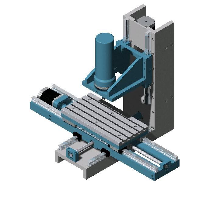
the way i "dream up" machinery of all kinds, i always try to get support close to where Forces apply to the structure, that's why for instance i built my machine with long guides, so the weight ( yes, it IS heavy ) is always evenly distributed.. DMG and Bridgeport have the same vision on this subject, why should i even consider another way, since my machine is specifically built for machining metal, if it can handle metal, it won't mind machining plastics and wood for that matter...
Progress is erhm... none at the moment, i'm waiting for info on guides and spindles.. PC is all Hooked up. steppers are mounted in the frame... just need them Guides and spindles to get the darn thing making some chips...
-
03-07-2007, 08:17 AM #90
Registered
- Join Date
- Oct 2005
- Posts
- 162
excluding downtime, (eg. waiting for rails & spindles,etc.) how long have you been planning & building this machine?
On the other hand, You have different fingers.
-
03-11-2007, 02:14 PM #91
Member
- Join Date
- Jan 2007
- Posts
- 352
Designing took me a week or so, building some 5 weeks, after work, and during lunchbreaks.. so basically 'bout 6 weeks..
-
03-12-2007, 12:56 AM #92
Gold Member
- Join Date
- Aug 2006
- Posts
- 1602
Any news on your linear slides? I'm gagging for another installment of wonderful pictures of your build!
-
03-12-2007, 08:52 AM #93
Registered
- Join Date
- Oct 2005
- Posts
- 162
Ditto!:cheers: Originally Posted by digits
 On the other hand, You have different fingers.
-
03-12-2007, 04:49 PM #94
Member
- Join Date
- Jan 2007
- Posts
- 352
no news yet.. (chair)those guys at Rexroth don't seem to be awake.. i requested some specs and prices.. got a phonecall 2 weeks ago, been on holiday last week, but no sign of em... i'd better... (nuts)
-
03-16-2007, 11:09 PM #95
Member
- Join Date
- Jan 2007
- Posts
- 352
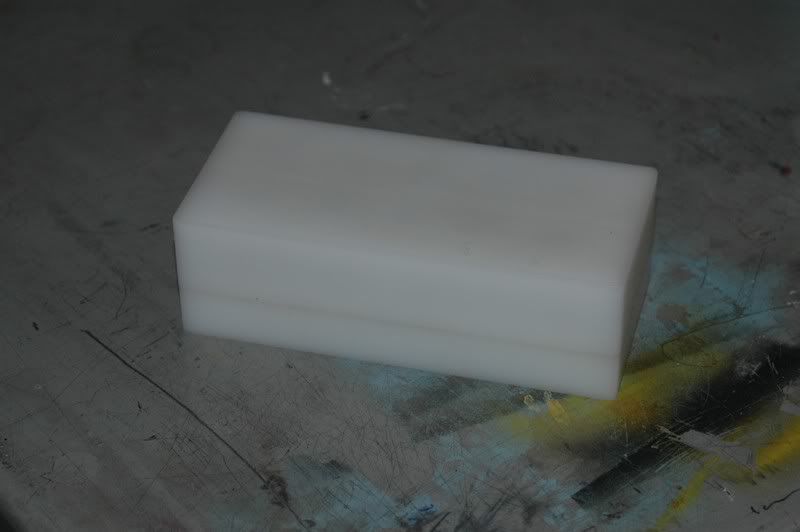
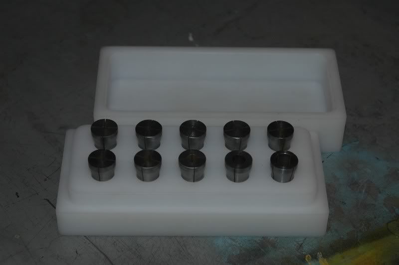
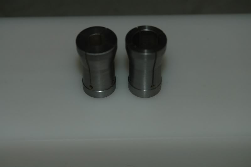
Yahooo.. Progress..
Today, i wire-eroded the last 9 out of ten collets.. and made a plastic ( Delrin ) container for them..
Hopefully next monday i will finally get an offer from Rexroth.. if not, i'll phone em tuesday morning before they had coffee, and call them "lots a bad, bad words"... they mailed me that i would have my offer today, or monday...
by the way, does anyone know how to get thruogh to the guys at CNC Zeus?.. posting an question on their forum has proved impossible for me sofar, and i don't get any reactions on mail i sent them sofar...
-
03-19-2007, 11:34 PM #96
Member
- Join Date
- Jan 2007
- Posts
- 352
Finally... i got the prices... boy... it's gonna cost me.. but hey.. i wanted everything free from backlash.. so.. i got what i wanted.. qualitiy materials.. total price: 2500 Euro..(nuts):withstupi..
the good news is: delivery of the stuff will take up to 16 weeks.. so i so have some time to gather some dosh..
and i've been thinking about a nice paintjob...
and.. i've designed some of them Toeclamps.. which i will probably mill tomorrow..
-
03-20-2007, 08:49 PM #97
Member
- Join Date
- Jan 2007
- Posts
- 352
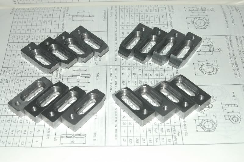
Finally some of them thar Toe clamps, 16 pieces.. two sets of 8.. no for a nice and neat plastic container like the one for the collets..
-
03-20-2007, 10:00 PM #98
Registered
- Join Date
- Mar 2005
- Posts
- 160
Nice machine.
Wow, I have never met anybody outside of my job, I work as a fork lift operator at a machine shop, use their vast experiences of machining and apply it to hobbies such as building homemade cnc machines as I do on cnczone.com. At work I am surrounded by machinist that total 6000 years of experience and their mentality is, "Why would I machine for a hobby, if I do it all day at work?" I am the guy who removes the scrap metal coming off the machining centers with my fork truck. Whenever i get a chance i watch the machinist and the machines cut an intricate piece out of nothing and find that fascinating. I was dismayed at the mentality of these machinists and thought, " hell, had i the experience to CNC machine I would use it all the time, for work and play every chance i get. So, because of cnczone.com and many of it's members, not to mention a small protest against the machinists mentality at my job, i am proud to anounce that I am in my second semester of Central Connecticut State University where I am majoring in mechanical engineering. This program has an advanced CNC course.
thanks to people such as Stevie and arie Kabaalstra and the rest to many to name who make hobby machining inspiring to look at, watch and enjoy, and in small part those who cannot fathom machining as a hobby. i am on my way to a better life and better oppurtunities, to boot.
i also celebrated by buying a few machines. i have a 7x12 seig mini lathe and a seig mini mill, i initially want to start small for three reasons it's within my budget, if i mess up it's within my budget and I rent an apartment. seeing that machines can be retrofitted with cnc i would like to try my hand at retro-ing these machines as i progress in my studies. for now, i am getting my hands dirty with building Xenon gas filled flashlights out of aluminum and other non ferrous metals. i hope to make a stainless steel flashlight soon. Arie as many others, I will be following your build. i think it's impressive and I wish you good luck in putting it together and godspeed.
this was just something i wanted to share, is all.
-
03-20-2007, 10:12 PM #99
Member
- Join Date
- Jan 2007
- Posts
- 352
Praetor,
i've been working with CNC's for 10 years now.. and i was just gettin bored with working late if i had to make something for myself.. that's why i started building my machine.. i still find it fascinating equipment to work with, and that's the second reason why i built mine.. Budgetwise, i think my machine covers your complete workshop, but hey!.. i wanted to have those flashy Zero backlash Bosch Rexroth thingies... at least i know my machine is built to last..
recently i found another benefit of building your own machines.. when applying for a job, i take my "Projectfile" with me, a portfolio with my drawings, electrical layout drawings, documentation, and spec's just to impress the people that are trying to figure out if i would be a good engineer/designer..
For your pleasure, and mine of course, i'll keep posting news about this little machine..
-
03-23-2007, 07:49 PM #100
Member
- Join Date
- Jan 2007
- Posts
- 352
Today, i fiddled around some more.. and i made a set of "Quadrails" as we call em.. i made 2 of these at work, some 8 years ago, and they've been my most trusty piece of "Clamping-tool"..
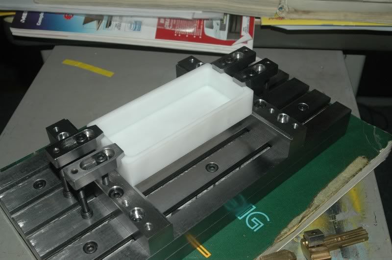
there's a little recess in the rail, to put workpieces in, when machining multiple parts, just slide out the old, and slide in a new part.. clamping can be done from 11 positions on each rail.. so there's always a good position to fix the part

 Reply With Quote
Similar Threads
-
more progress..
By adam_m in forum DIY CNC Router Table MachinesReplies: 0Last Post: 11-26-2013, 03:56 AM -
Design In Progress
By JoeDawg in forum Uncategorised MetalWorking MachinesReplies: 1Last Post: 10-07-2008, 07:48 PM -
My First Router Design & Progress
By watsonstudios in forum CNC Wood Router Project LogReplies: 40Last Post: 07-22-2007, 09:19 AM -
Looking into buidling an Auto-start RPC
By Wendell in forum Phase ConvertersReplies: 2Last Post: 10-12-2006, 03:03 AM -
Alibre design in progress
By xyzcnc in forum Uncategorised CAD DiscussionReplies: 10Last Post: 06-07-2005, 06:49 AM
