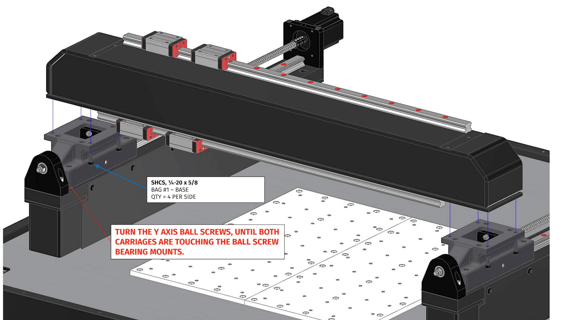
Hi Mogi - This is the arrangement you should be modelling. The force is at the tool, so use a dummy tool with infinite stiffness. Ive attached a guide to machine testing Peter
shooting at 20N/um the spindle plate and the Z plate will need flanges or be very thick. My Z axis is flanged and is equivalent to around 60mm thick steel.
Results 1 to 20 of 160
Hybrid View
-
03-15-2023, 12:18 PM #1
 Member
- Join Date
- Jul 2018
- Posts
- 6453
Re: Gantry 3-axis milling machine Design preparation phase
-
03-15-2023, 07:50 PM #2
 Member
- Join Date
- Feb 2023
- Posts
- 66
-
03-15-2023, 09:05 PM #3
 Member
- Join Date
- Jul 2018
- Posts
- 6453
Re: Gantry 3-axis milling machine Design preparation phase
Hi Mogi - I have been thinking about how to machine the gantry and here's how Langmuir do it I think:
1) The gantry is fabricated and the top and bottom plates are 1-2mm thicker then needed as a machining allowance. Its stitched together not 100% welded which is wise. Plus the "flanges" created are useful for clamping edges
2) Then its sent to heat treat for stress relief. Now it can be machined in confidence its not going to move
3) The bottom surface is set up and faced to best fit and the perimeter is machined to create reference edges. Holes are drilled and tapped, bottom is complete
4) Its released turned over, clocked to edges & the top is machined - all good
Now you are going to get a cold rolled welded SHS so its a bit different unless you get it TSR - it will have lots of internal stress in it trying to change the tubes shape
1) Pick your best face of the SHS it will be crowned vs hollowed. This is the face to machine first (ideally you take this to a heat treater and TSR the SHS so you can move fwd in confidence)
2) you will clamp at the ends or hold in two big vices - half face the first face , release and check it out. Then clamp back and finish machine flat. Release and inspect. If it warps or bows stop here! if good Drill and thread all the bottom holes.
3) Decide which end is the reference end, machine square, machine a reference land the length of the SHS on one of the vertical sides
4) release and set up on the new reference face, use the reference end and the register land to clock the part. Now you know where all the bottom details are so you can machine the top in register
5) rough the top face, release the part and check, clamp back down, re-clock then finish machine
At this point if Venus has aligned and the machinist held his tongue right it will be flat and straight with no twist. If it has warped then you have a problem. If you can TSR the SHS its a very small cost compared to getting to this point and trying to recover the part.
A cold rolled and welded hollow section has quite a bit of internal stress in it and then you have to hold it somehow which will deflect it again. That's why you can't clamp it and machine in one go as the clamping deflection will be machined into the part....
Good luck - Peter
When machining large moulds in aluminium they are cut and released and rested several times through the process. Its quite interesting how much metal moves when machined and clamped.... The forum is full of "please help" threads using SHS or RHS and then the cars jam. Get the bearing manual and look up the manufactures specs for geometric tolerance of the rail lands and scare the machinist, Do the best you can with what you've got and fingers crossed
-
03-16-2023, 09:07 AM #4
 Member
- Join Date
- Feb 2023
- Posts
- 66
Hi Peter, I'm thinking same as langmuir did it

welded steel plates and bend the top one to be like langmuir gantry includijg 5mm flange on both side because I found a place that is doing heat treatment and they would do the gantry which is 200mm x 200mm x 1000mm make it reach 600c+-15c and keep it there for 2 hours then cool down slowly for not more than 40$ the part Wright is 125kg that i toke the quote for. So it's smaller size and weight it will be even cheaper.
Because I calculated if I wanna build heat treatment oven my self that is 40cm square and 115cm long and about 12kw power it will cost me about 850$ about the 12kw my electric can support even more if I want to draw.


 Reply With Quote


